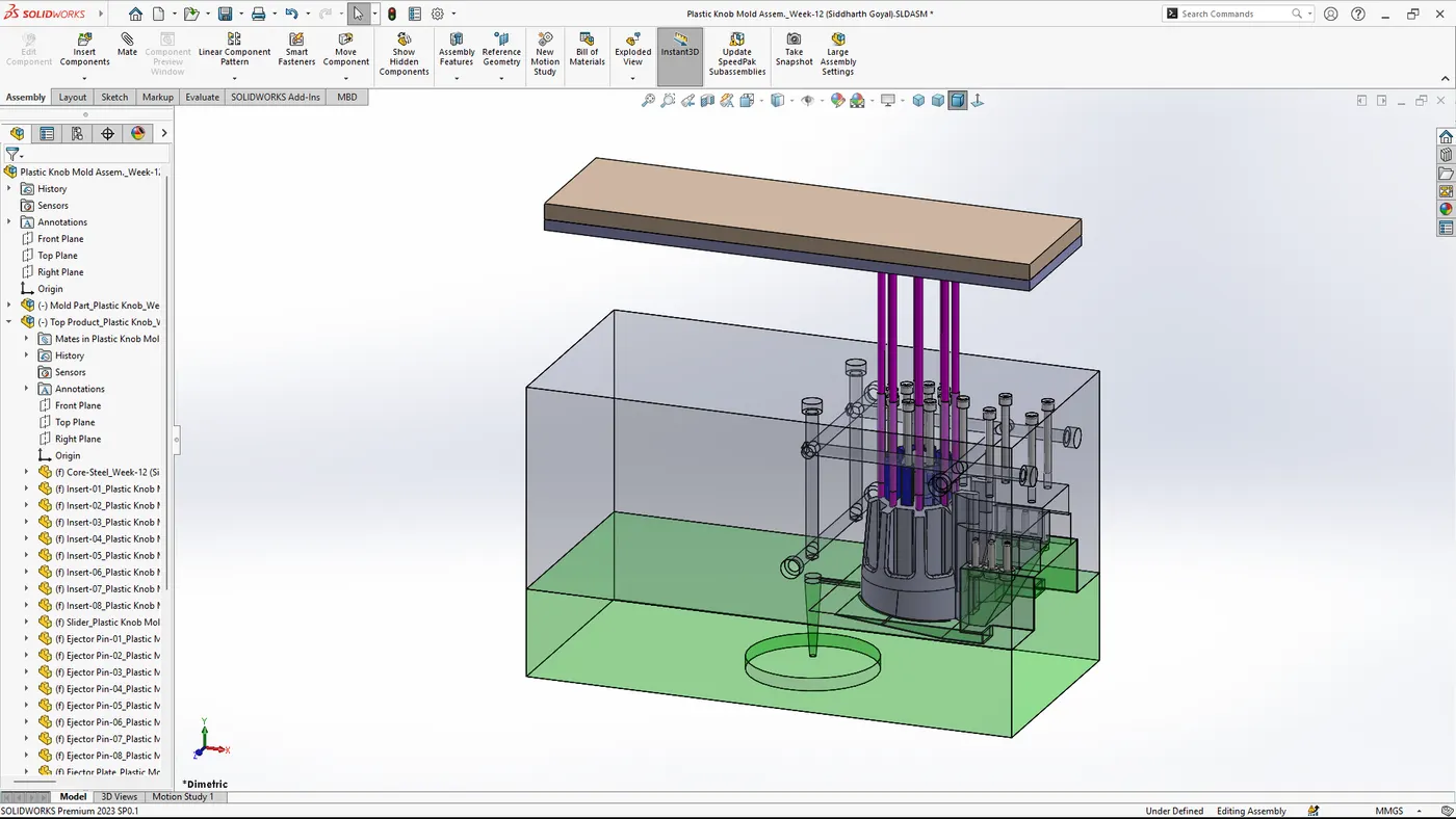
Week 12 Challenge
Designing the proper ejection system with ejector pins and plates, runner and gate system, air vents, and cooling channels for a mold using SolidWorks.
1. Initial Setup and Part Design
- Start SolidWorks: Open SolidWorks and create a new part document.
- Design the Part: Use the various sketch and feature tools to design the part that will be molded. Ensure the part is designed considering draft angles for easy ejection.
2. Mold Design
- Insert Mold Tool: Go to 'Insert' > 'Molds' > 'Tooling Split'.
- Parting Line: Define the parting line by selecting the edges where the mold halves will separate.
- Shut-off Surfaces: Define shut-off surfaces to close any holes or gaps in the parting surface.
- Parting Surface: Create a parting surface that extends out from the parting line.
3. Core and Cavity
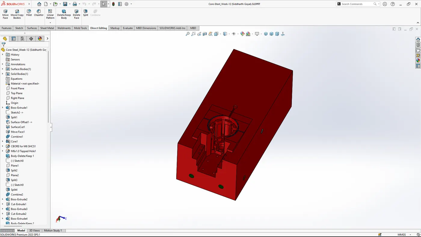
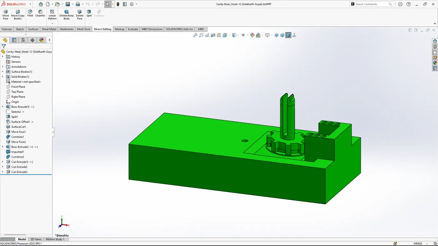
- Core and Cavity Extraction: Use the 'Tooling Split' to create the core and cavity blocks from the parting surface.
4. Ejection System
- Ejector Pins and Plates:
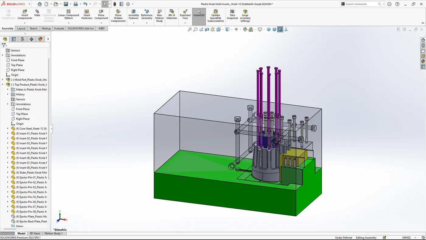
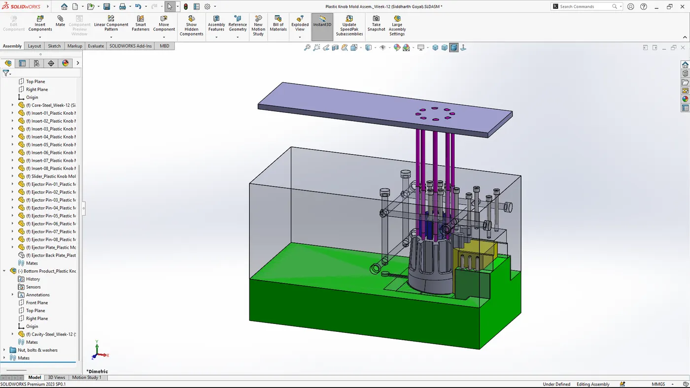
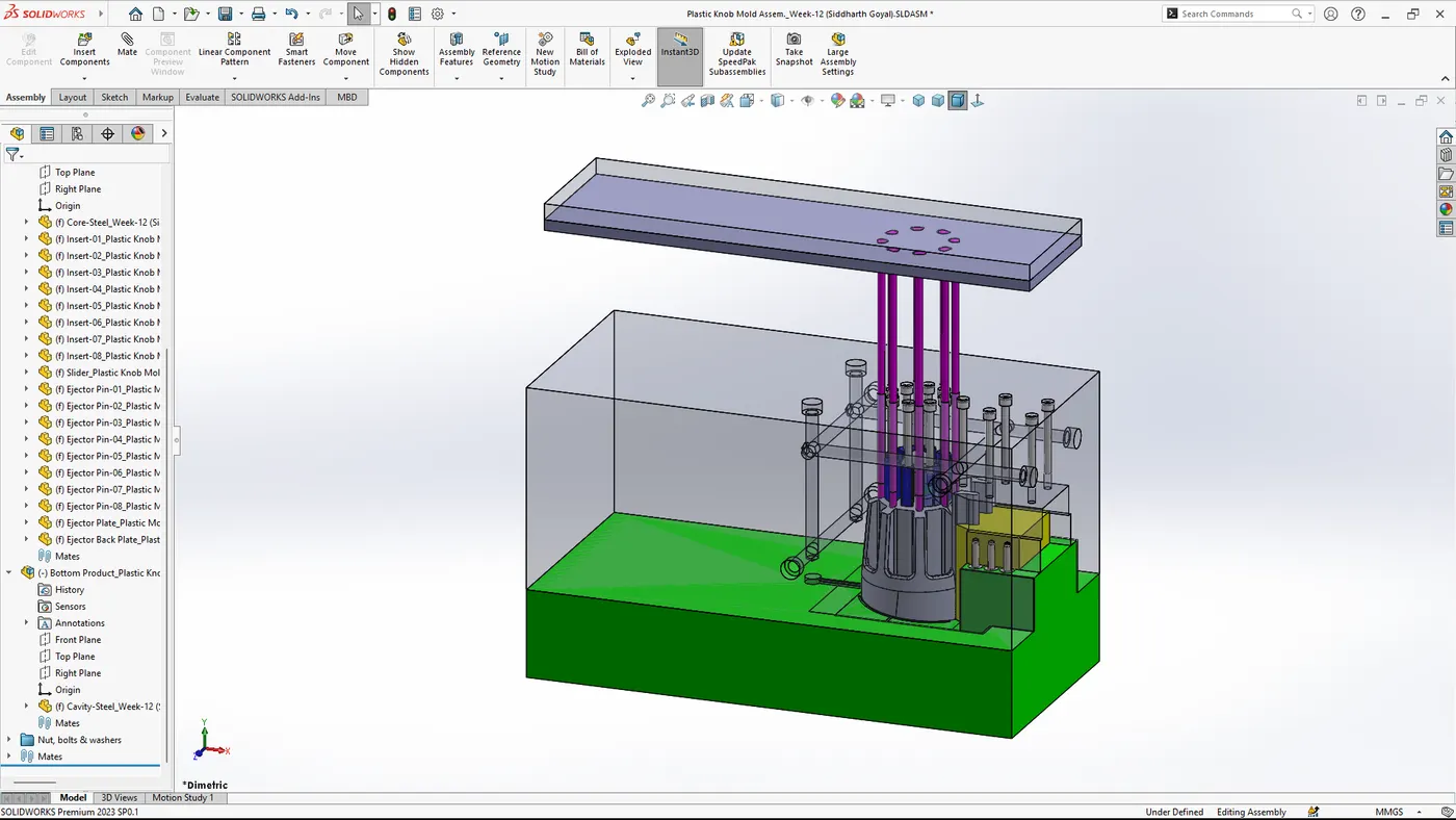
Open the mold base assembly and insert the ejector pins. Go to 'Insert Components' > 'Mold Base'.
Select standard ejector pins from the library or create custom pins. Position them strategically to ensure even ejection.
Create ejector plates that will hold the ejector pins. These plates are usually positioned on the bottom half of the mold.
5. Runner and Gate System
- Design the Runner System:
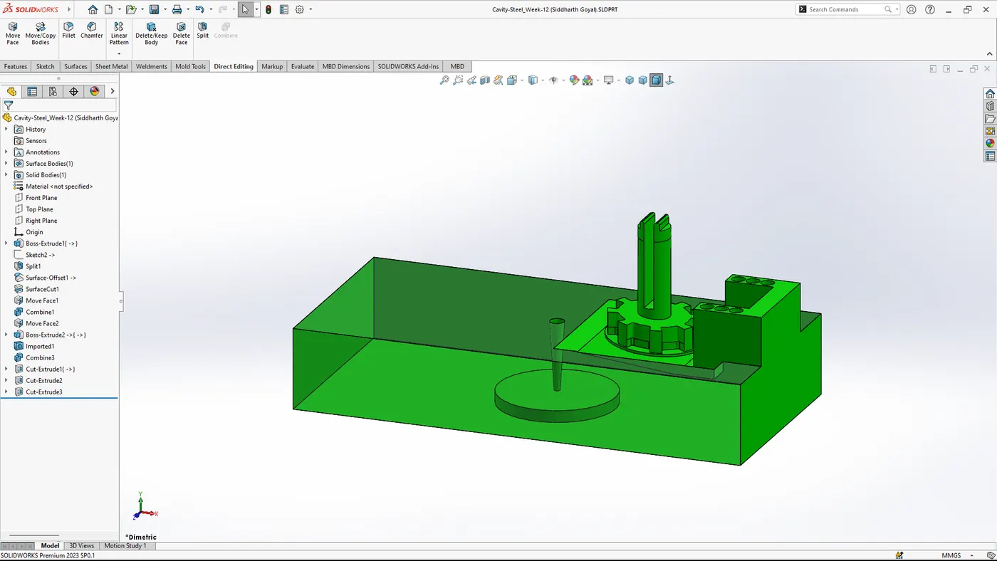
Use the 'Sketch' tool to design the runner system, which will guide the molten plastic from the injection point to the mold cavities.
Use 'Boss-Extrude' or similar features to create the runner paths.
- Create the Gate:
Design the gate, which is the entry point from the runner to the part cavity. This can be a sprue gate, edge gate, or any other type depending on the part design and mold requirements.
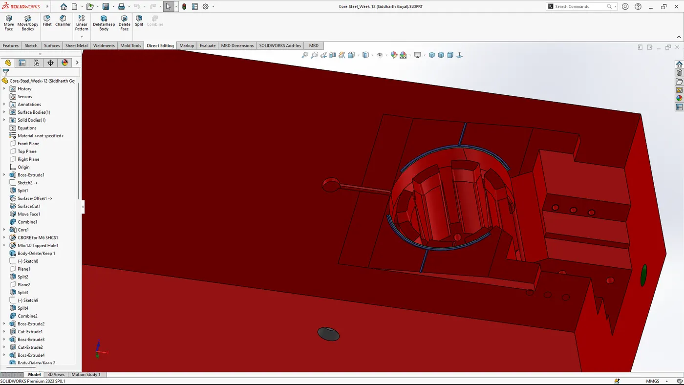
6. Air Vents
- Design Vents:
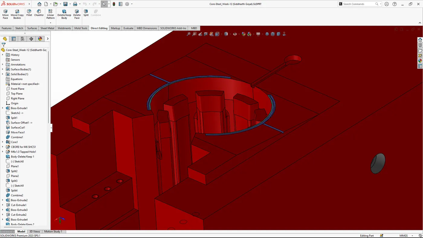
Add air vents to allow trapped air to escape from the mold cavity. These can be designed as small channels leading out from the cavity to the outside of the mold.
Use the 'Sketch' tool to create thin channels and extrude them slightly.
7. Cooling Channels
- Design Cooling Channels:
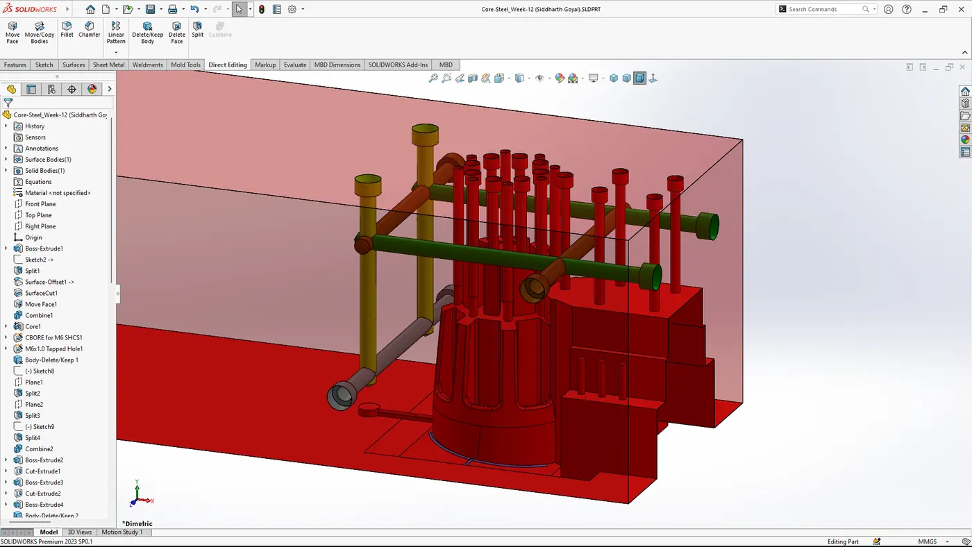
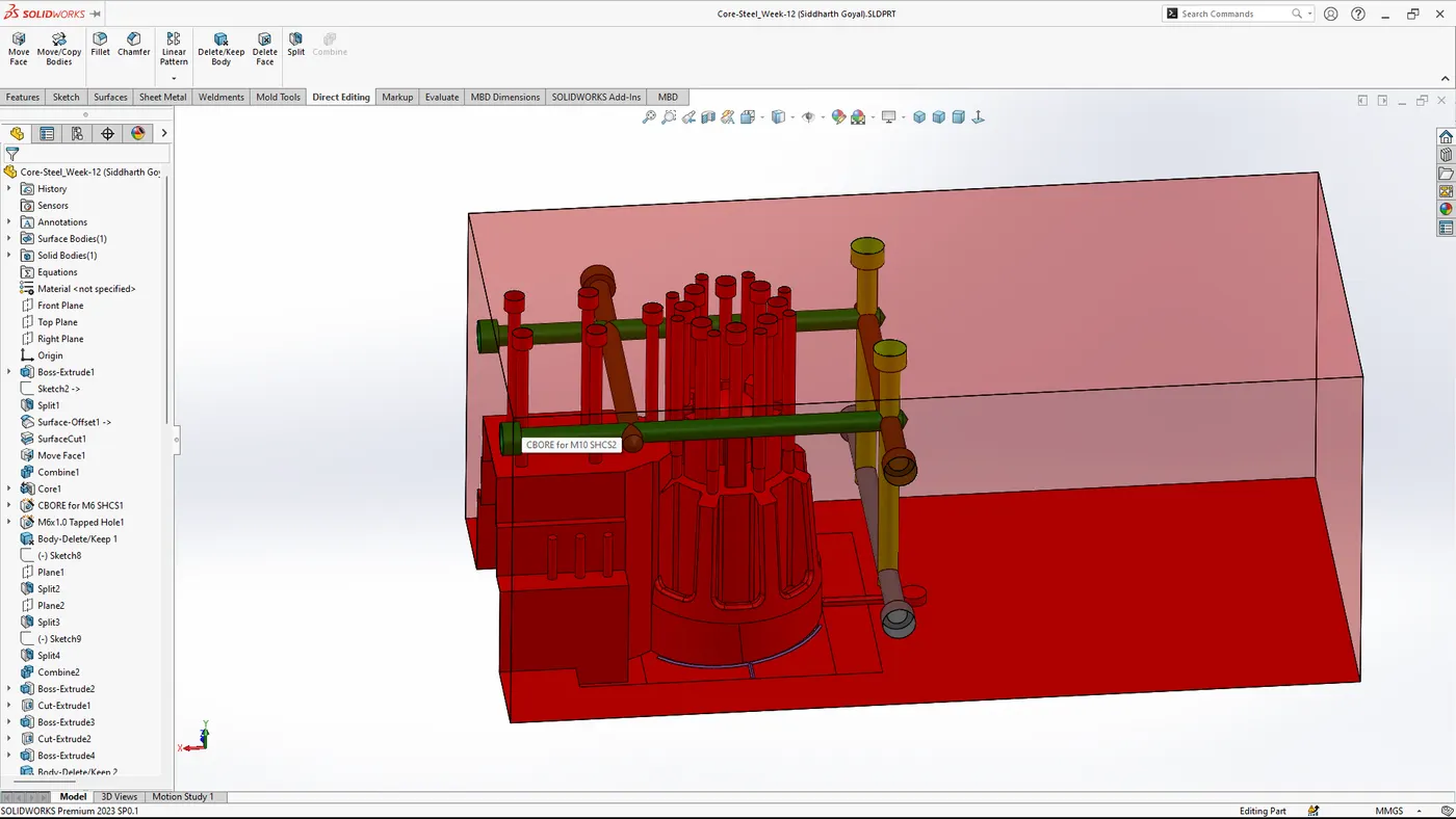
Use the 'Sketch' tool to design the path of the cooling channels. These should be strategically placed to ensure even cooling of the part.
Use 'Hole Wizard' or similar tools to create the cooling channels. Typically, these are drilled holes with a consistent diameter.
- Add Connectors: Include inlet and outlet connectors for the cooling channels to allow water or coolant to flow through the mold.
8. Assembly and Finalization
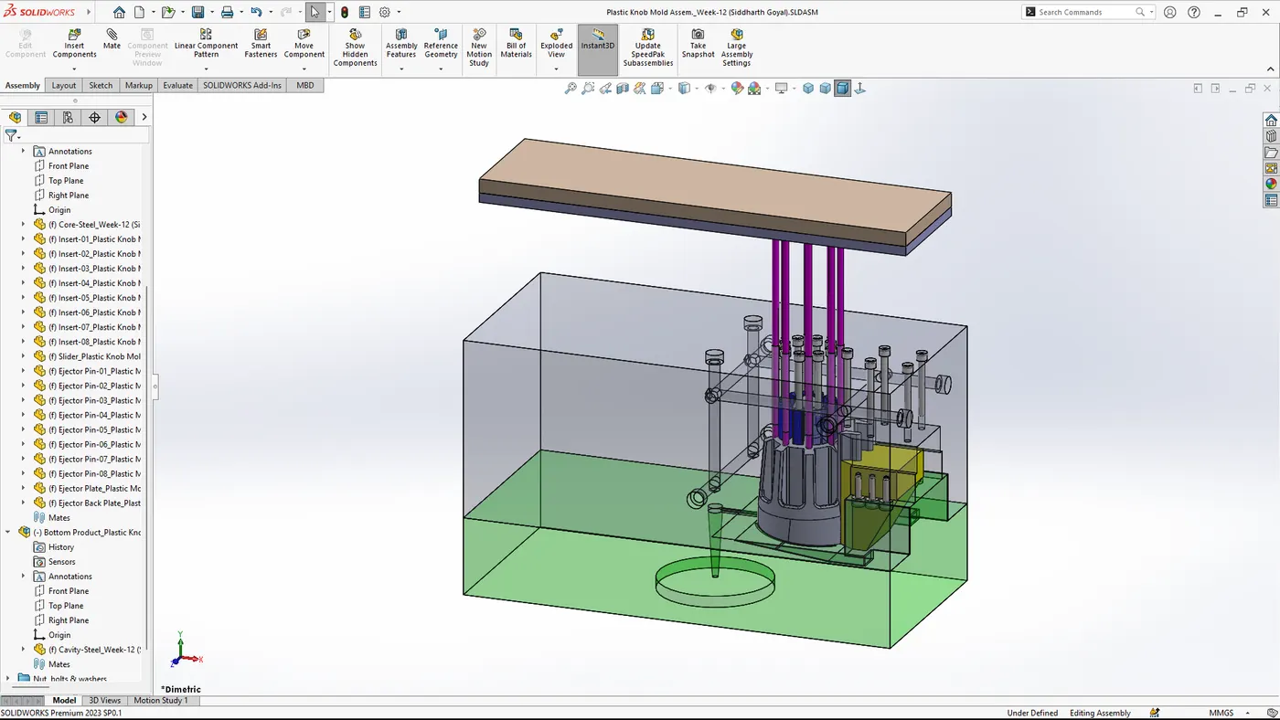
- Assemble Components: Ensure all components, including the core, cavity, ejector system, runner, gate, vents, and cooling channels, are properly assembled.
- Check Interferences: Use the 'Interference Detection' tool to ensure no parts interfere with each other.
- Simulation and Analysis: Run mold flow simulation to analyze the filling, cooling, and ejection processes. Make necessary adjustments based on the simulation results.