Week 12 Challenge
PLASTIC KNOB DESIGN FOR EJECTOR PINS, EJECTION PLATE, BACK PLATE, SPRUE, RUNNER, GATE, AIR VENTS AND COOLING CHANNELS.
INPUT:
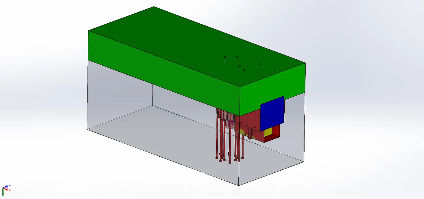
OUTPUT:
STEPS FOLLOWED:
Ejector Pins, Ejector Plate and Back Plate:
In Core Block,
- Sketch is made for Ejector pins of 6mm diameter. Using Core command the ejector pins bodies (light colored) are obtained.
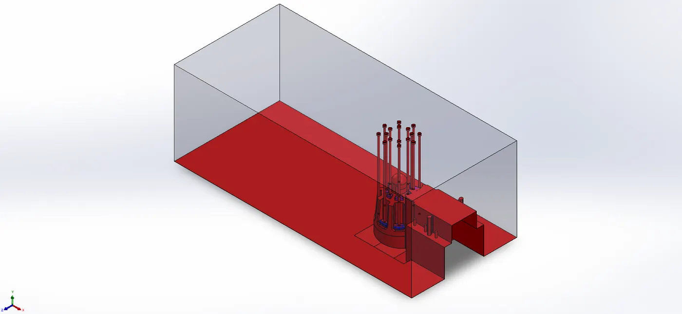
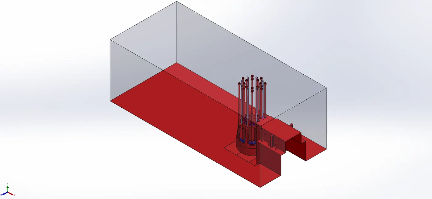
- Relief of 6.95mm at approximate distance of 14mm from starting surface is done.
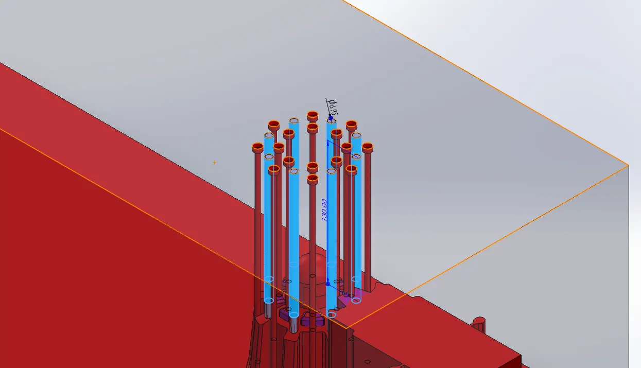
- The Pins are then extended at distance equal to the required stroke for ejection of component i.e.Plastic knob.
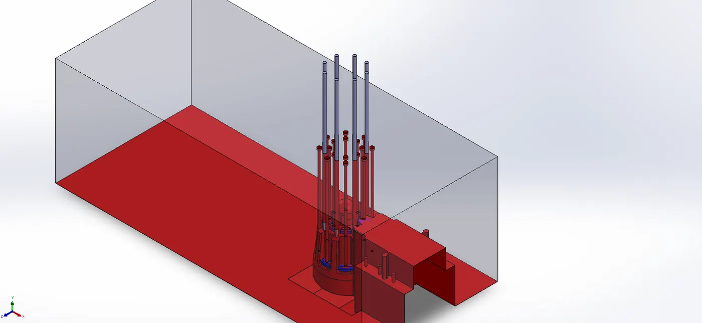
- As the end surface of the pins is at an angle i.e not normal to length of pins, so D-shaped head are made for each pin.
Also, the flat side of the sketch for pin head is made such that it touches the maximum length point of each pin.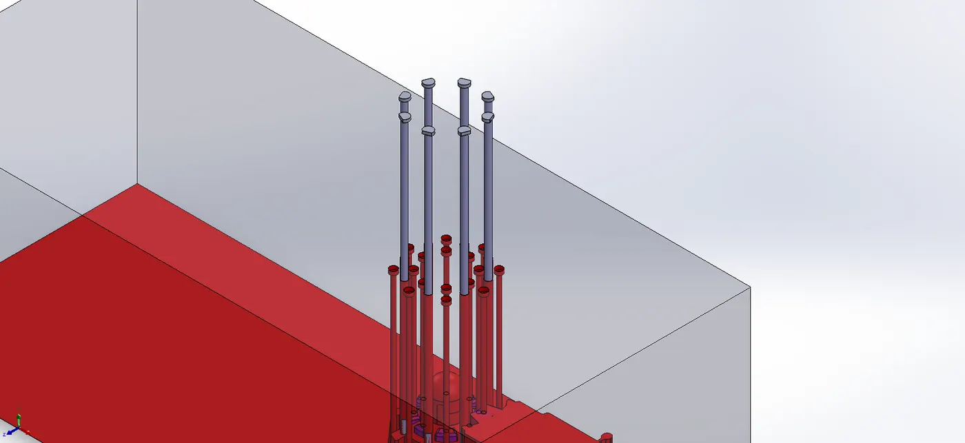
- Ejector Plate is made of same length as of core block, but with width of offset of 45mm on each side to core block.
2mm radial relief is done while creating slot for D-shaped head of pins of same thickness. Also general 6.95mm dia hole is done for remaining thickness of plate.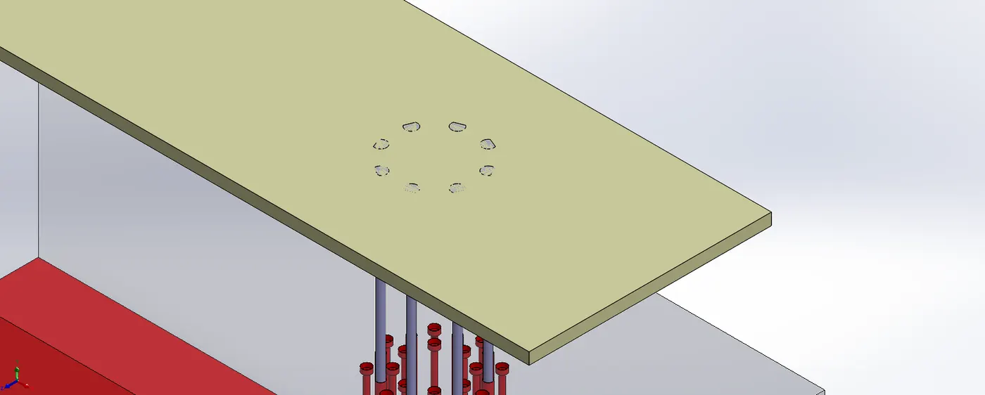
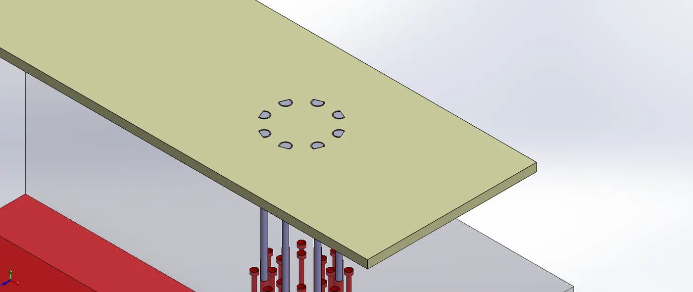
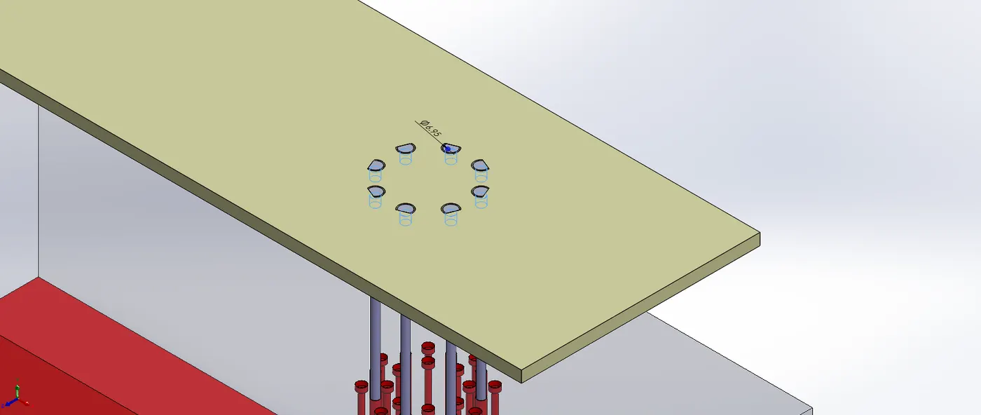
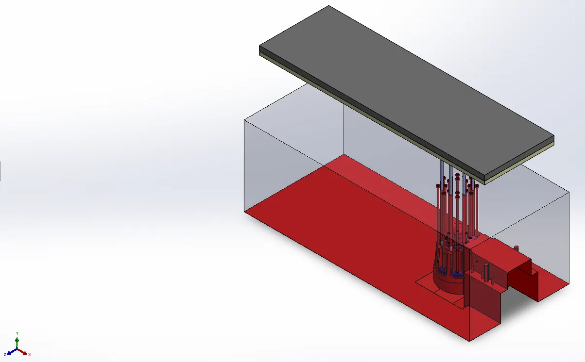
- Back Plate (dark Grey colored) of same size as ejector plate (Lime colored) but of 15mm thickness is made.
Sprue, Runner and Gate:
In CAVITY BLOCK,
- 120mm diameter depression is made at Cavity block origin projection.
- 5.6mm dia through hole having 3.5 deg taper outward is made at centre of depressed feature.
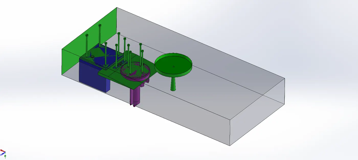
In CORE BLOCK,
- The core end of tapered sprue is projected onto the core body, and 5mm deep slot is made from it.
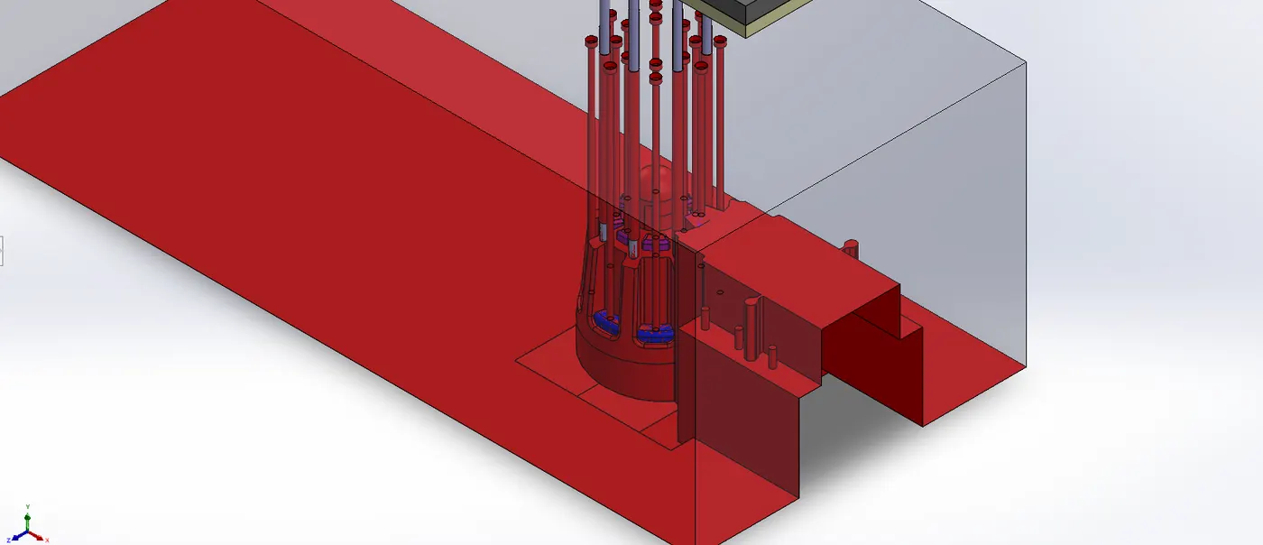
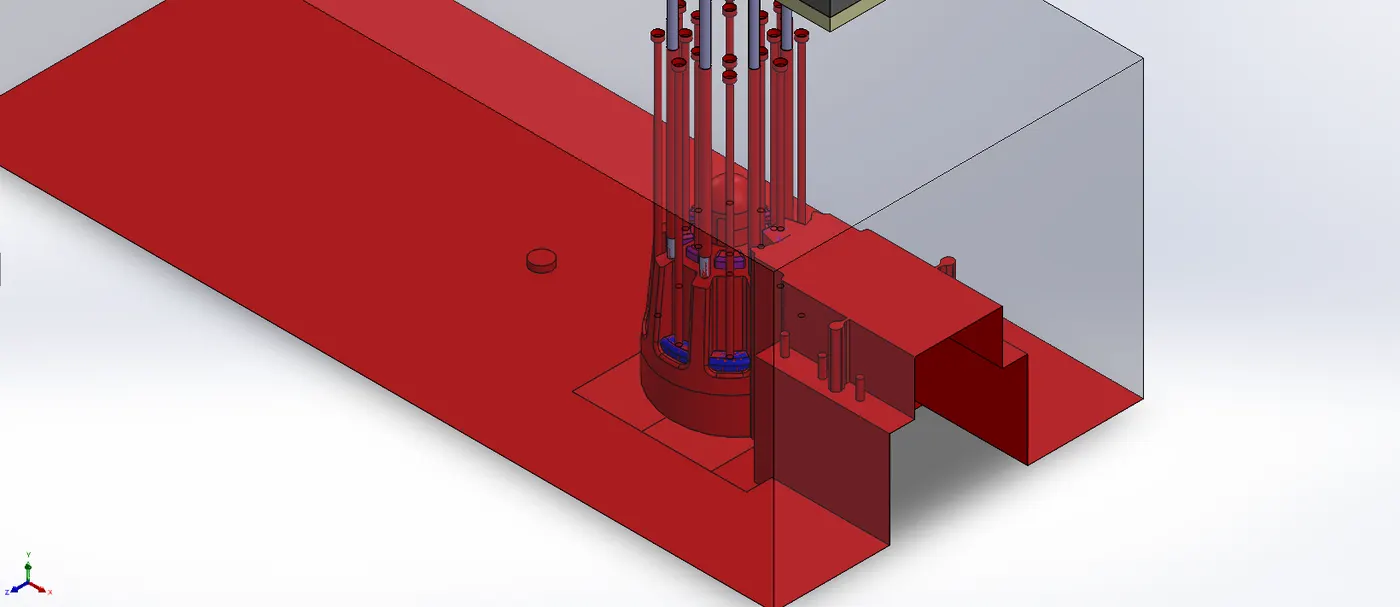
- Runner body is created of 9.5mm width and 4mm depth.
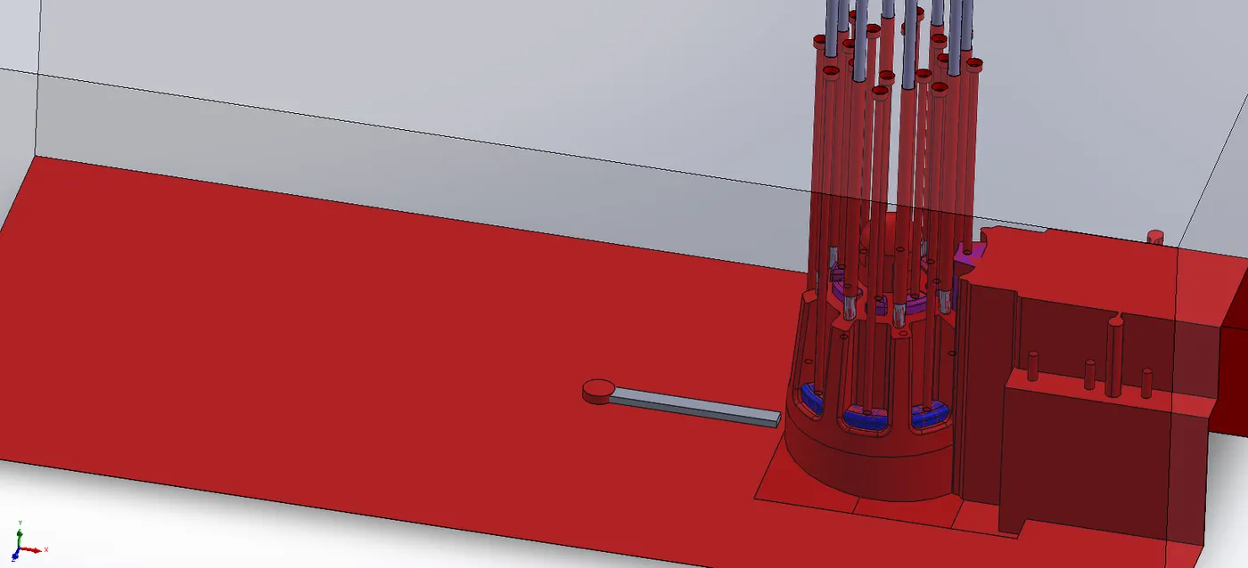
- Gate body is created. Taper of 40deg is given to front face to direct flow of plastic towards the component.
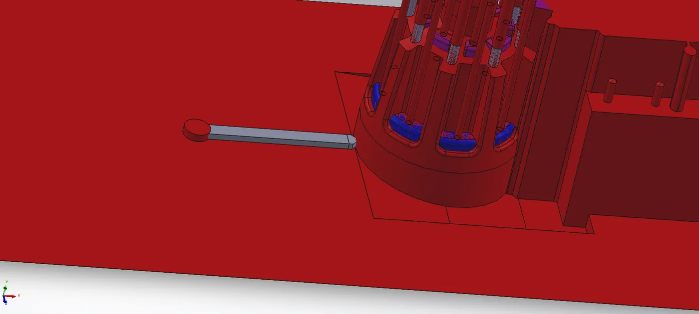
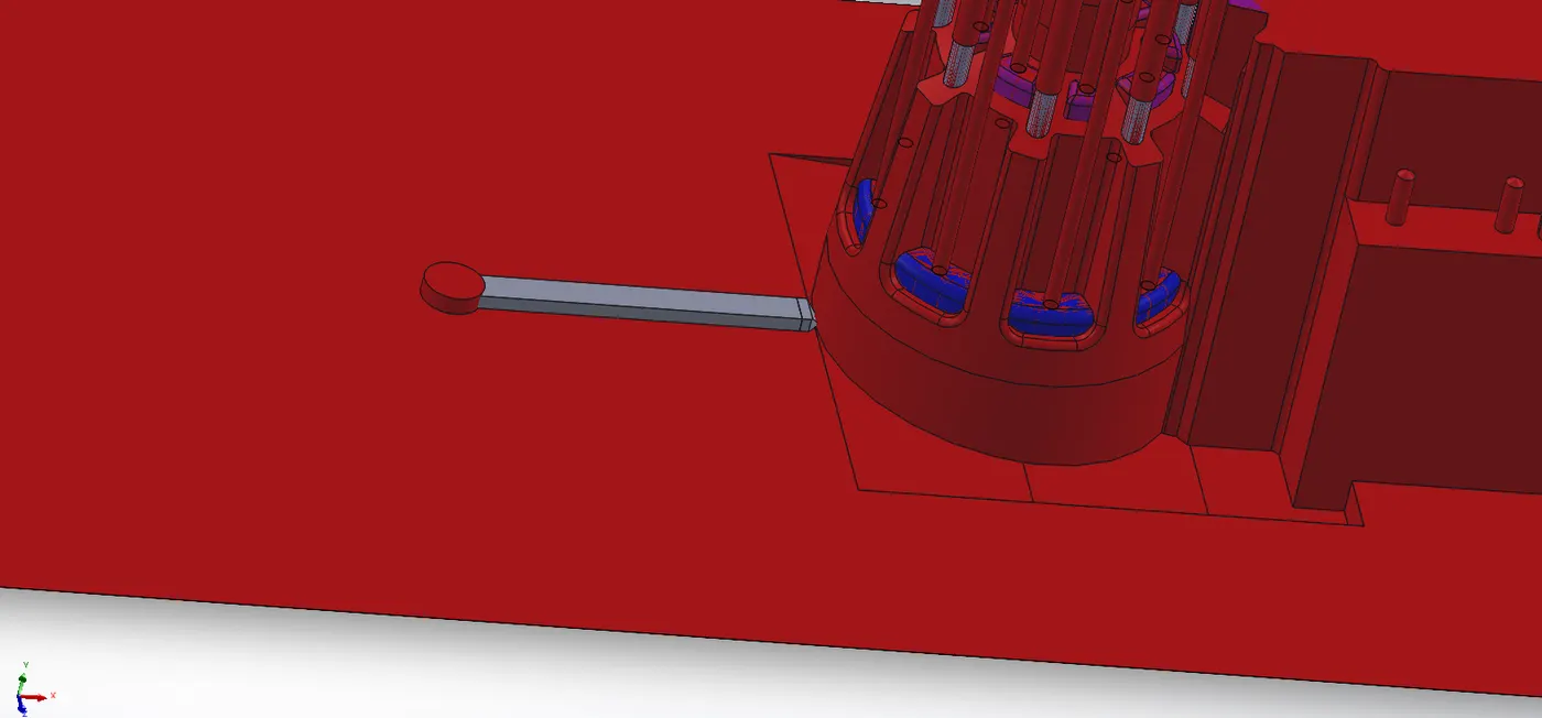
- Runner and gate bodies are joined using COMBINE command, and fillets were added to the edges.
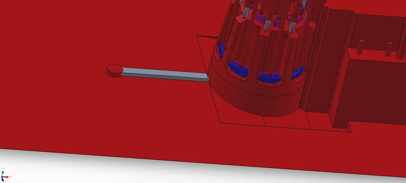
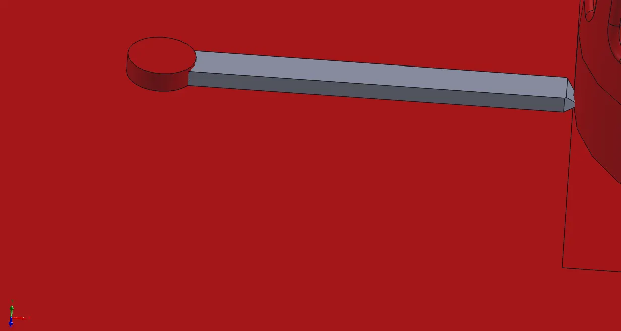
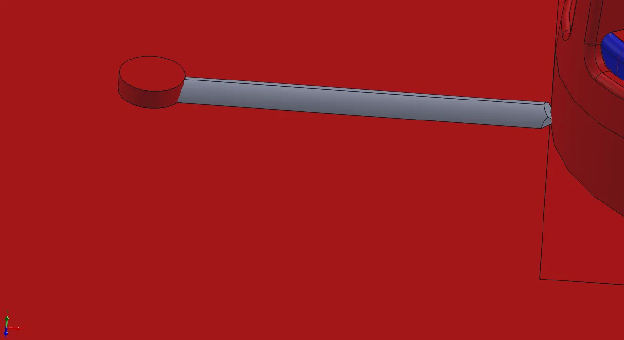
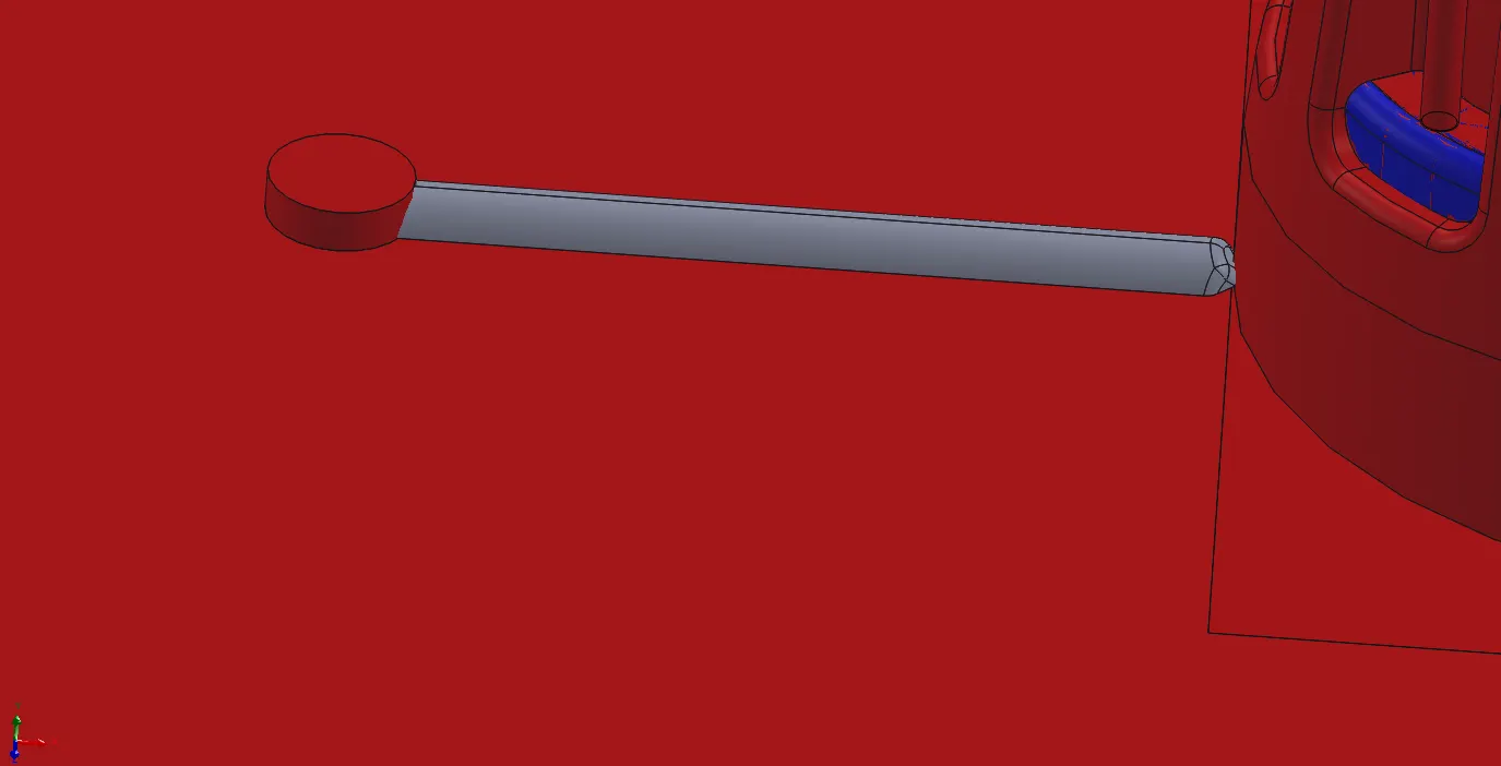
- Face of runner is moved to distance of 1mm. The using COMBINE command is subtracted from core body.
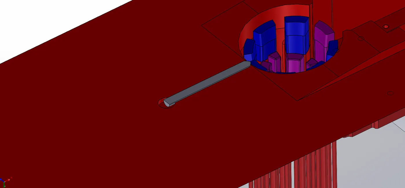
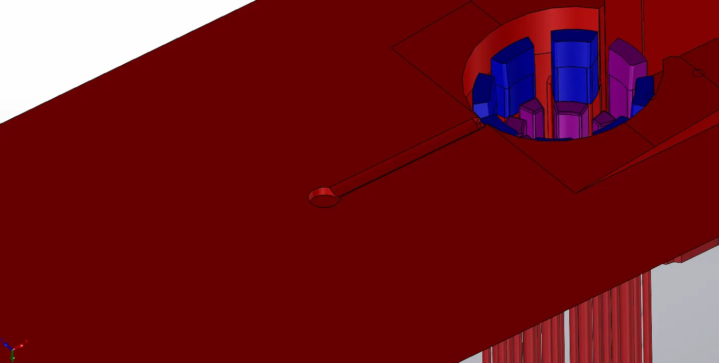
Air Vents :
Air vents are necessary for avoiding any air entrappment defects in the final component after it is cooled after Injection Molding processes.
An semi-circular extrude is produced around the component in the core block. It is splitted using angled plane on which it lies.
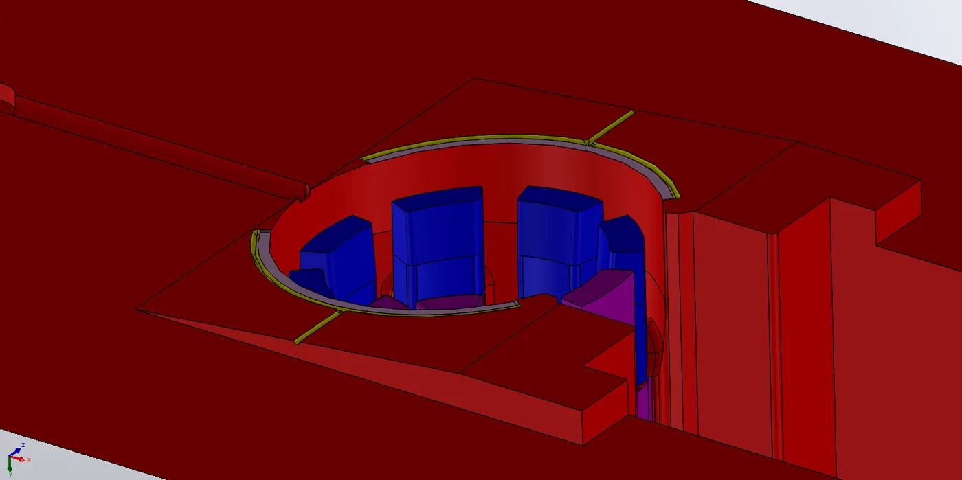
Extra material of 1mm is added onto the bottom face for creating the slot for venting of air.
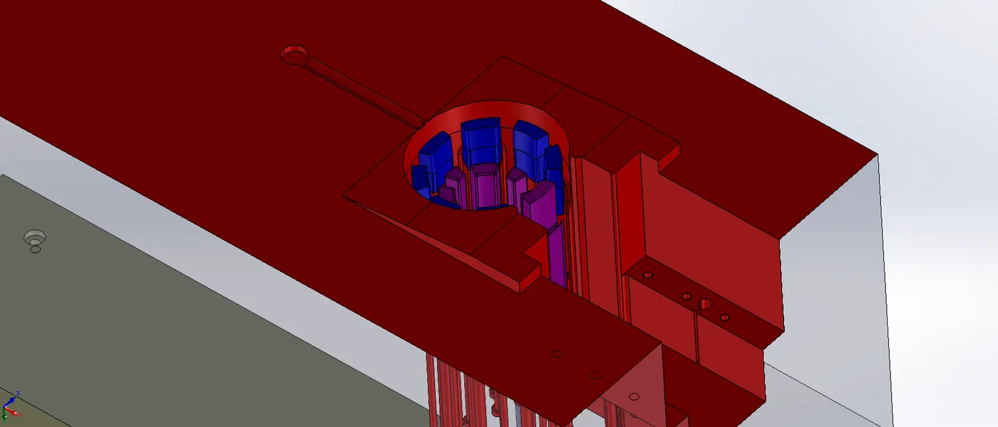
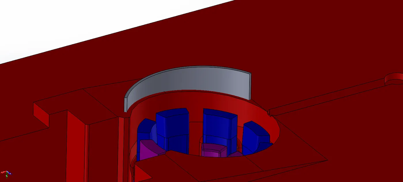
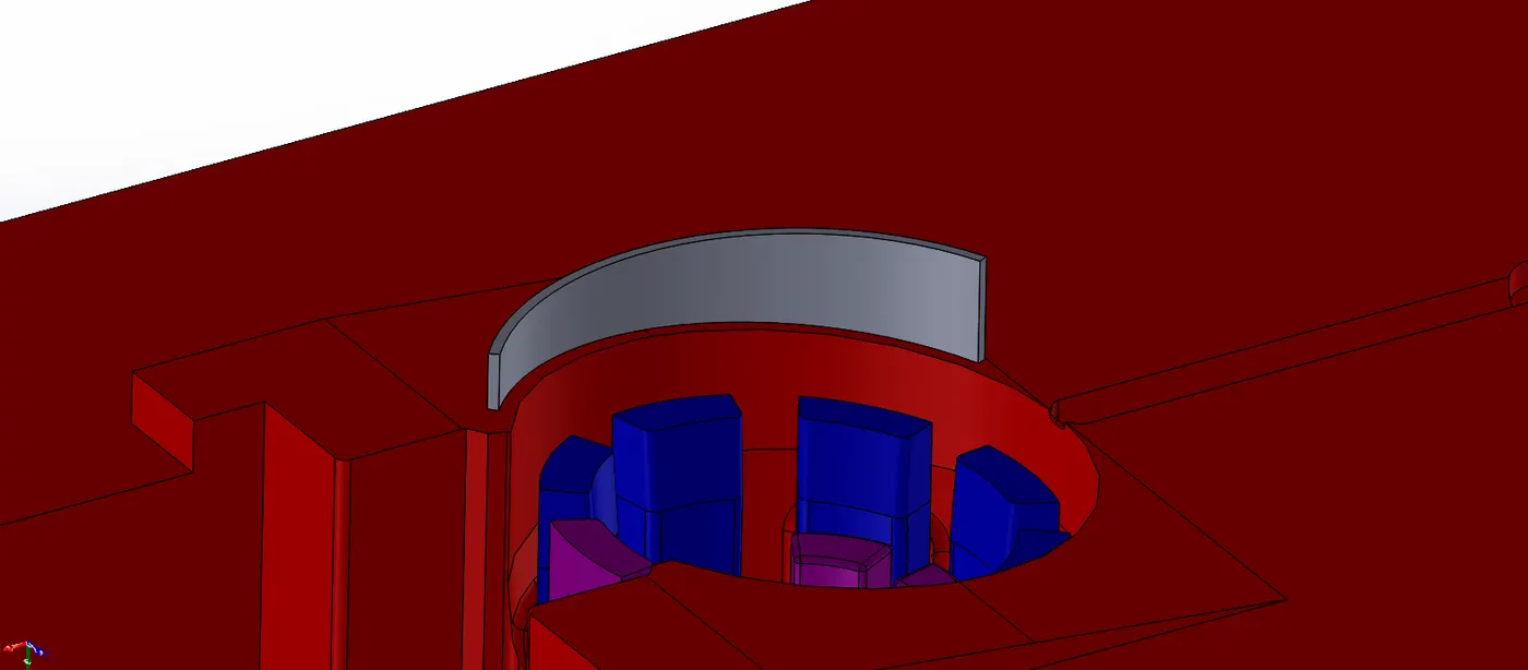
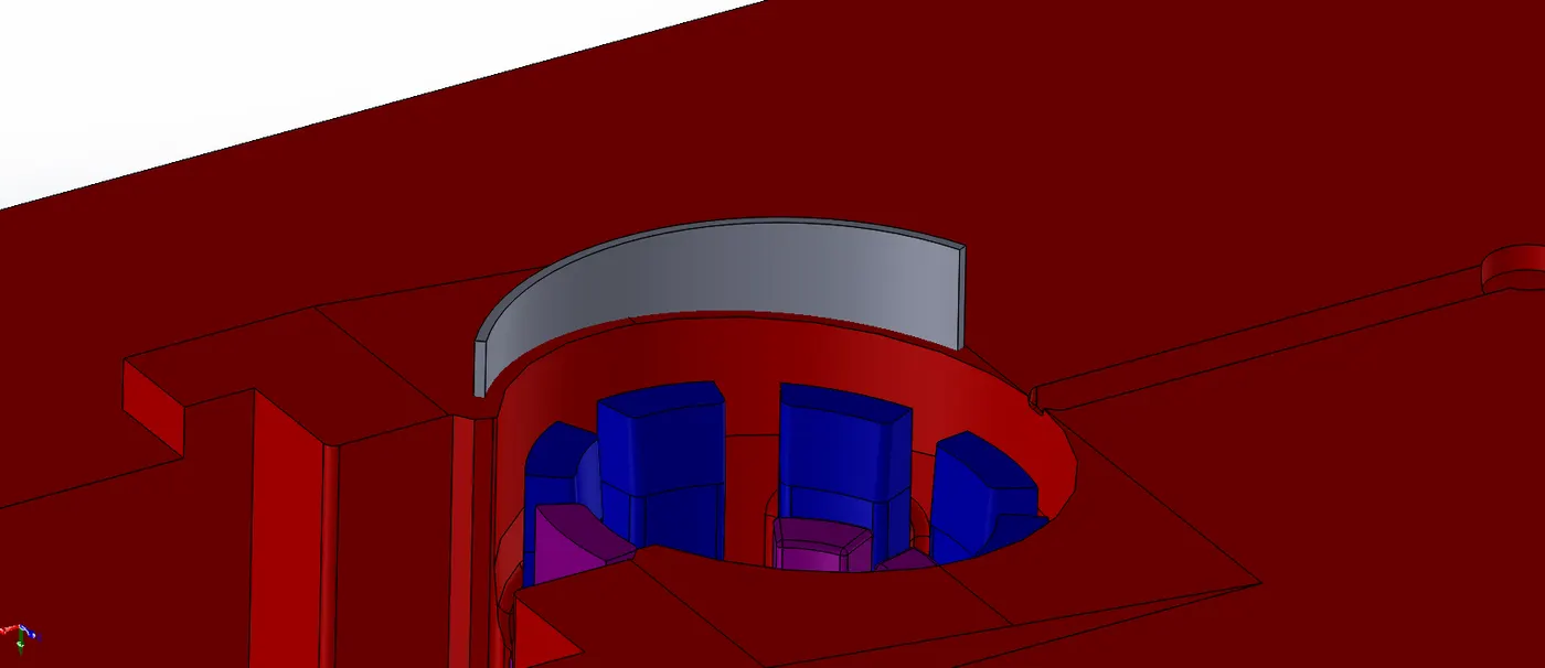
Similarly, the remaining surface between the extrude done and the circular edge is extruded. This is done for achieving 0.3mm slot near the 1mm one.
For this, similar to above the body is splitted and material is added on its bottom.

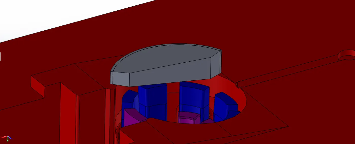
Fillets of 1mm are done to edges.
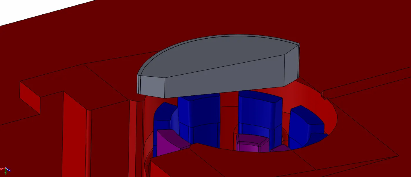
For venting the air further to outside of block, an strip of 2mm thickness is extruded as separate body.
This will help air come out via the relief gap of 2mm that was provided in initial stage of Core and Cavity block design.
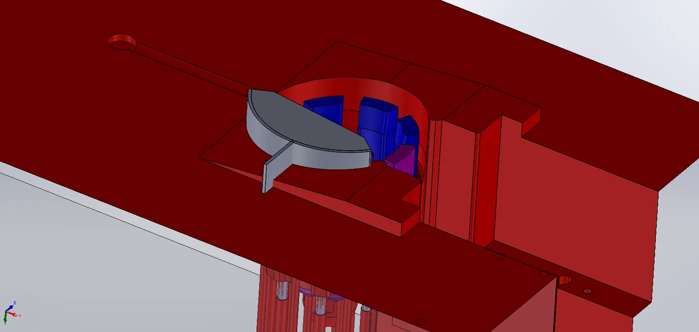
The extruded part is spilted and 1mm material is added to bottom face just as done in previous steps.
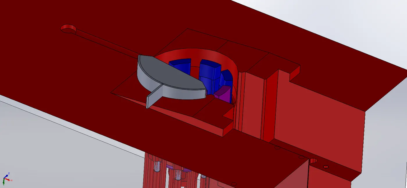
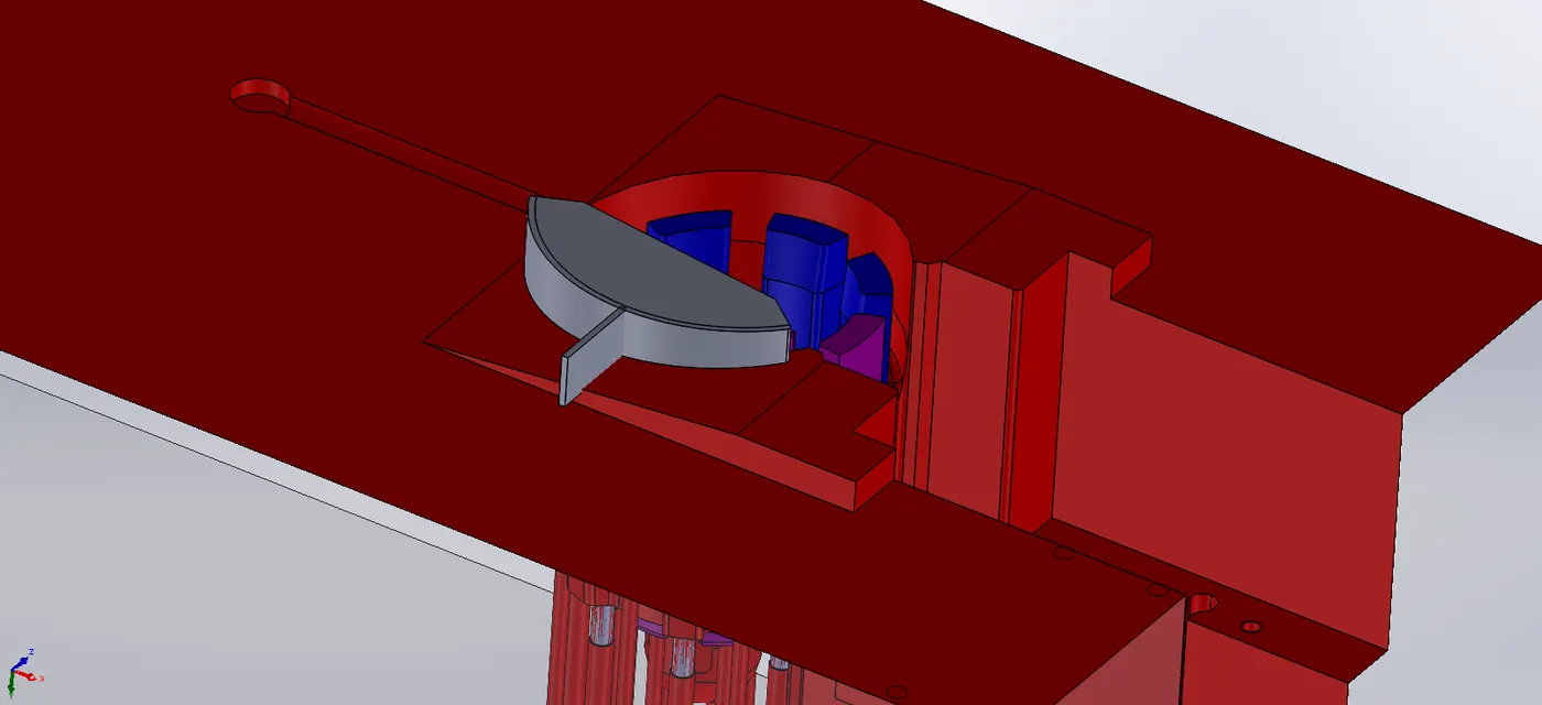
Fillet of 1mm is added on lower edges.
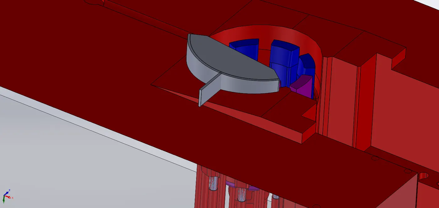
All 3 bodies are then joined using COMBINE command.
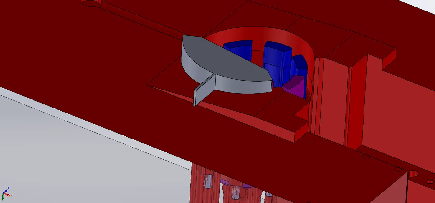
Fillets are added to remaining edges.
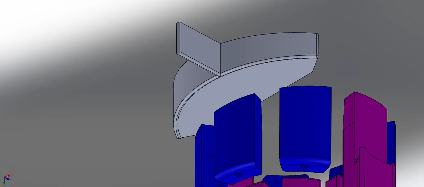
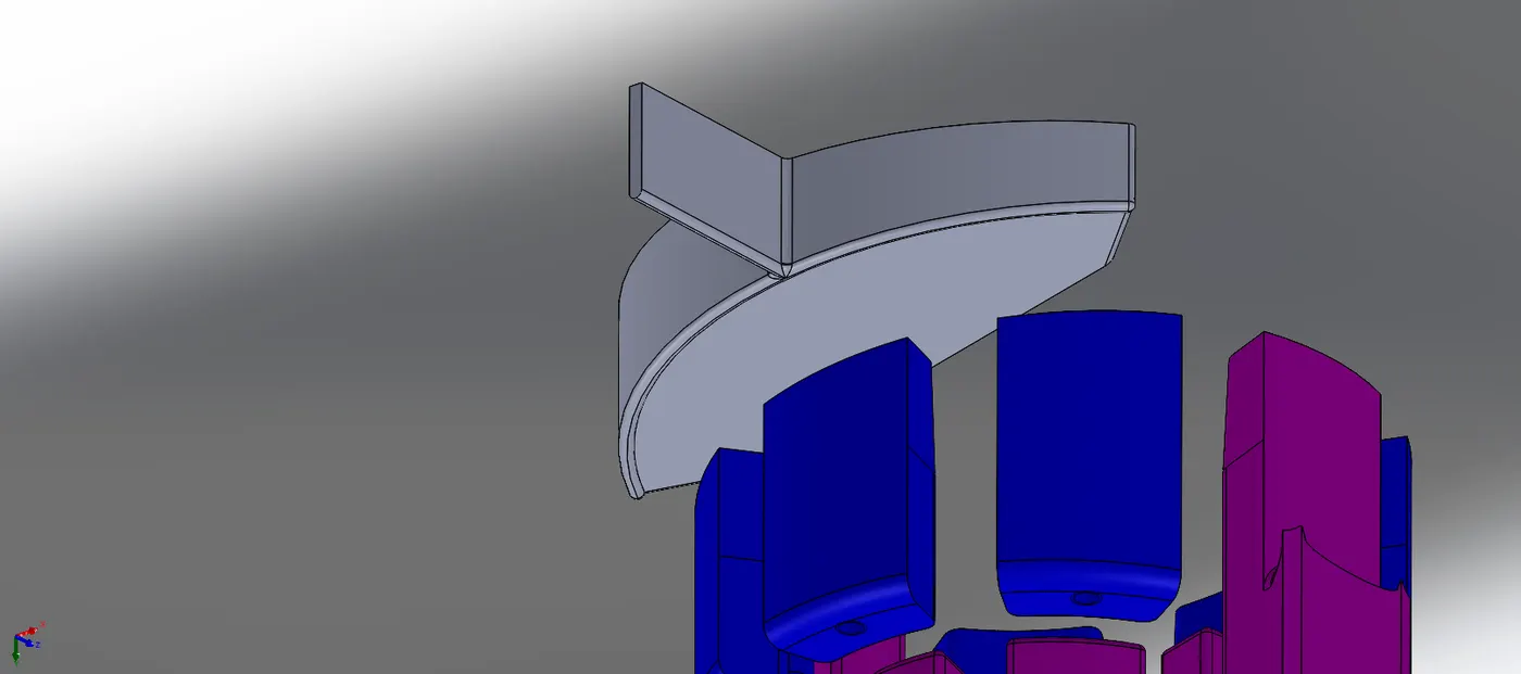
Now the slot body is mirrored, and then subtracted from the block.
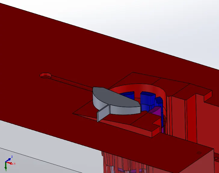
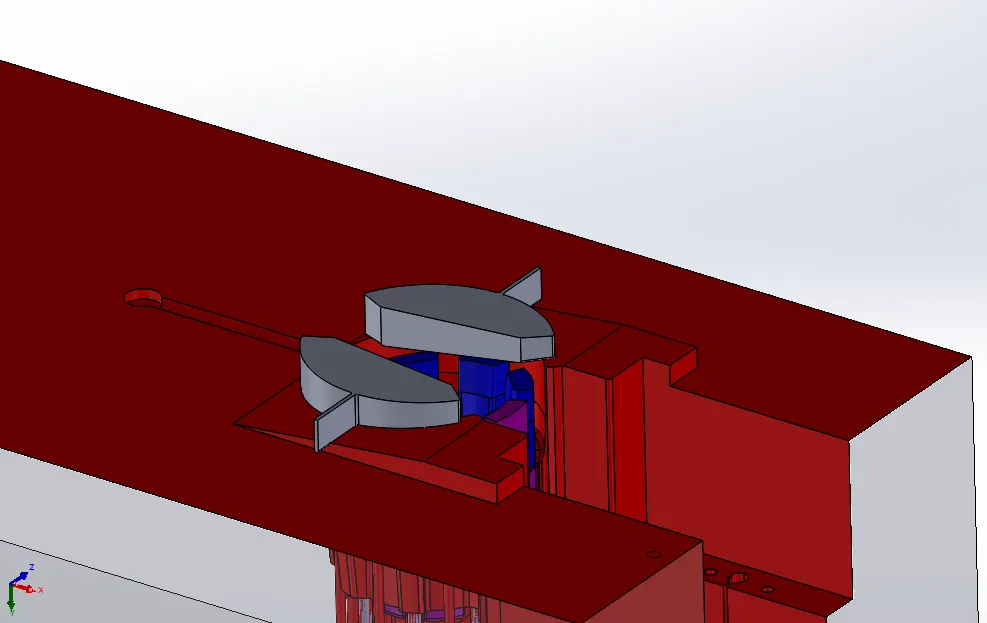
The Yellow colored slot shows the 1mm slot.
And, the Pink colored one shows the 0.3mm depression.
Cooling Channels:
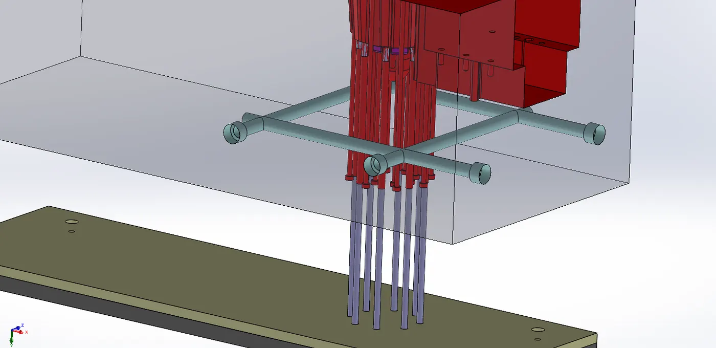
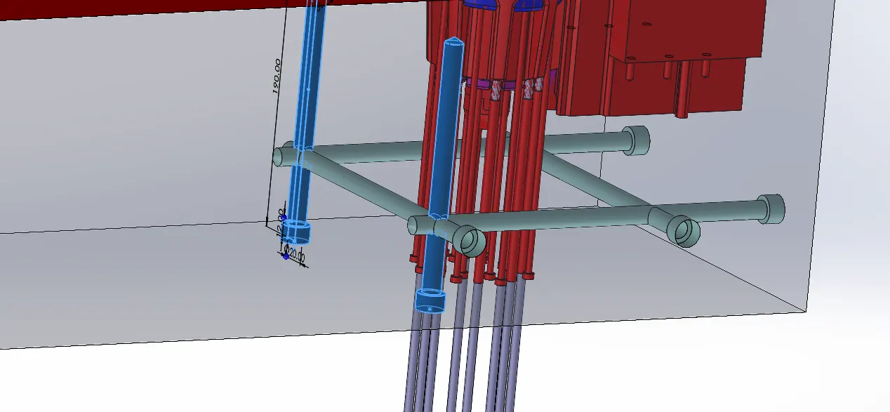
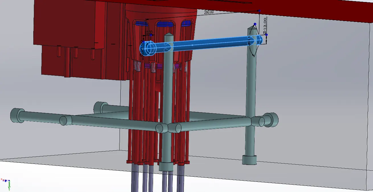
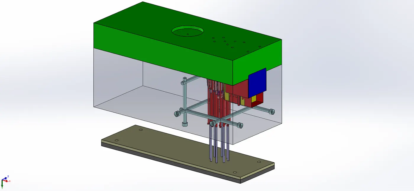
Inlet and Outlet channels are done using CounterBore hole of 12mm dia size.
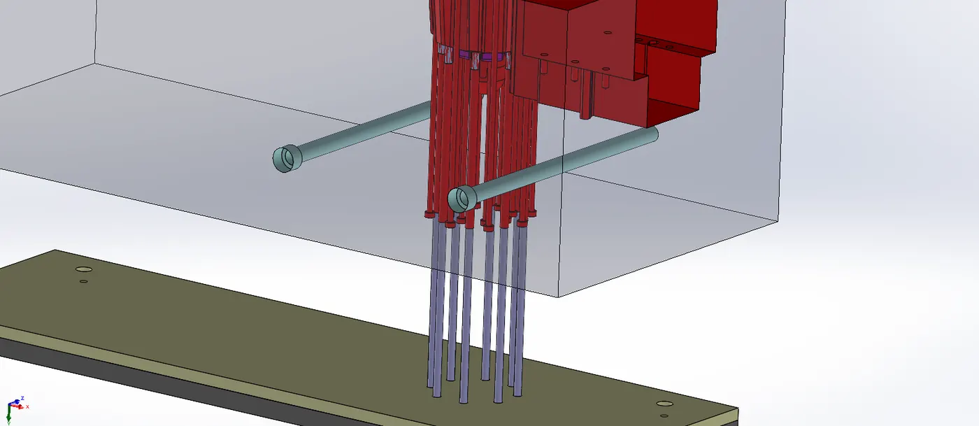
Then, Further channels were added to have adequate cooling as shown below.