Week 12 Challenge
1. Create alignment plans in sheets.
2. Create roadway double stack plans in sheets.
3. Create plan and profile sheets.
4. Create cross sections sheets.
1. Create alignment plans in sheets.
- Open ORD=>TE=>TI
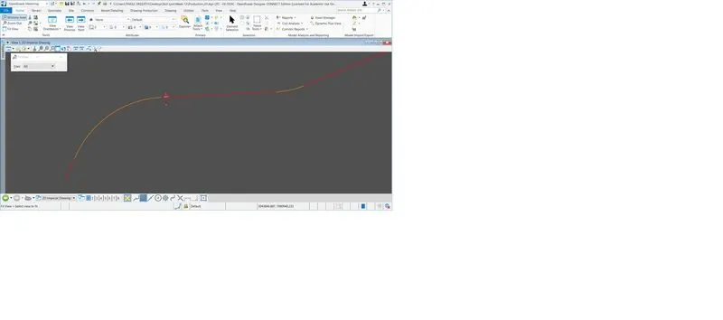
- Open a new file=>browse seed files=>select Sheets=> select 2D drawing production=> give name as Production_01.dgn=>Blank file opens up=>now go ahead and attach project mainline alignment.dgn file via interactive method (nesting depth=0) and file opens up.
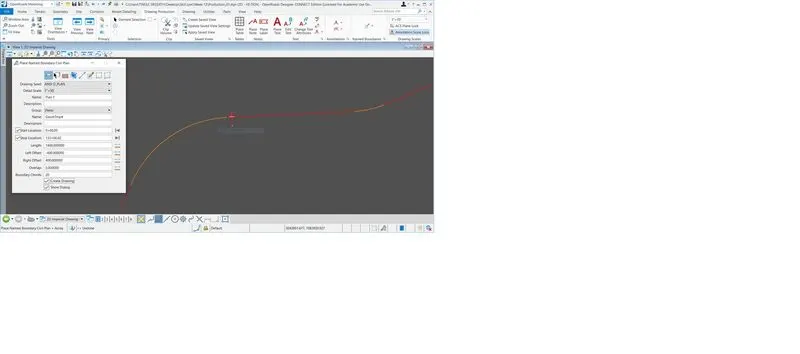
- Now select the named boundary=>click on the named boundary=>window opens up=>select and fill the window as shown below.
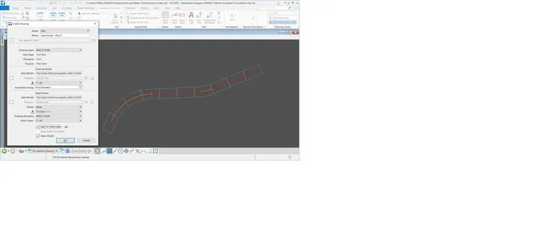
- Accept it=>create drawing window appears and fill in the window as shown below.
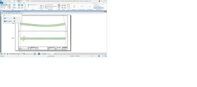
- Click OK=>now the drawings have been created=> it can be seen by as shown below.
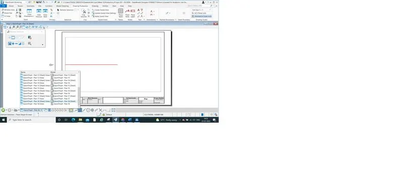
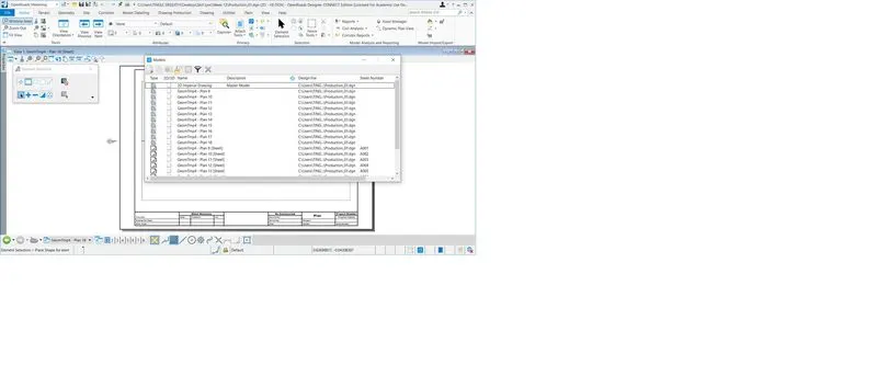
- It can be noted that 18 drawings have been created. Drawings can also be seen by going into Home tab=>Primary=>models as shown below.
- Note: It can be noted that 2 sets pf drawings have been created one with boundary another one without the boundary which is a clipped boundary.
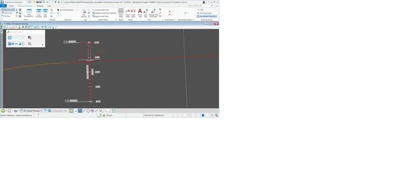
- Now go to Drawing productions=> select the default view=>Annotations=>Element annotations=>annotations will automatically appear on the drawing based on the assigned FD.
2. Create roadway double stack plans in sheets.
- The procedure for creating the double stack plans will be explained in detail below.
- Open ORD=>new file and name it Production_02.dgn=>browse 2D Drawing production seed file=>attach both roadway plan.dgn and project mainline alignment.dgn via interactive method
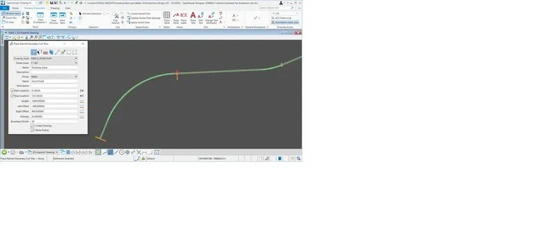
- Now select named boundaries=> place a named boundary=>select ANSI D PLAN PLAN and fill out the window as shown below.
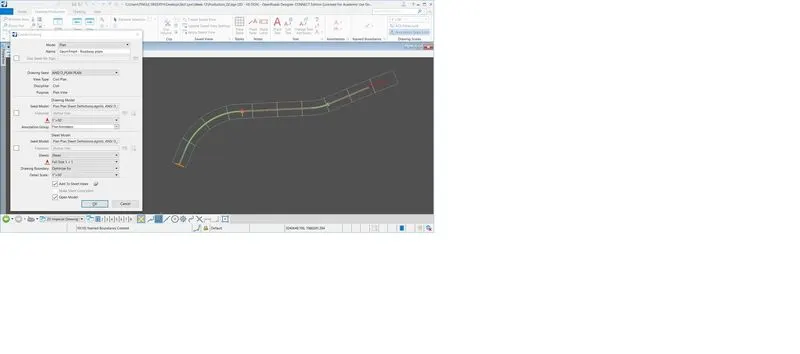
- Do a data point and the command processes. A new window opens up.
- Click OK and then the new drawings are created as shown below.
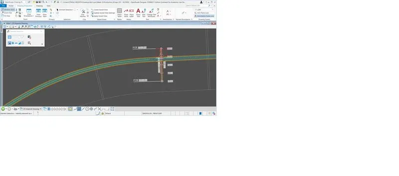
- Now go to default drawing model view-2D imperial drawing model. Now go to annotations=>element annotation=>pick CL and reset to complete. Annotations can be seen as below.
- Text can be placed on the drawing with Place a text command.
- Thus, Roadway double stack plans can be created.
3. Create plan and profile sheets.
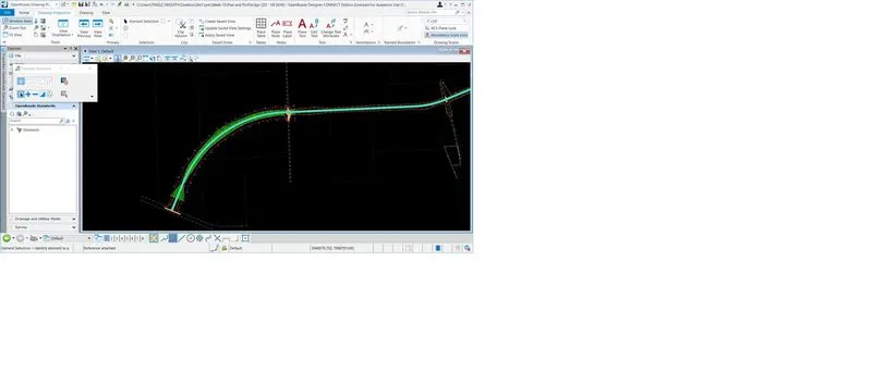
- Open ORD=>Training and Examples=>select Training Imperial=>select 2D Imperial Design seed file=>name the file as Plan and Profile. File opens up
- Go ahead and attach corridor basics.dgn with live nesting 1.
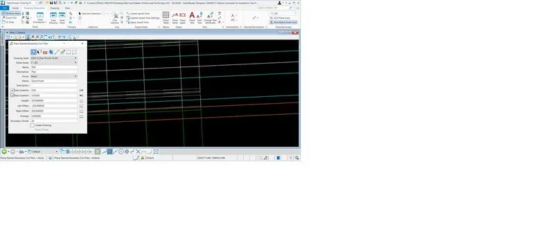
- Click on the Named Boundaries=> create named boundaries=> fill out the table as shown below.
- Note: Uncheck the create drawing box as in this case drawings should be produced after creating profile named boundaries.
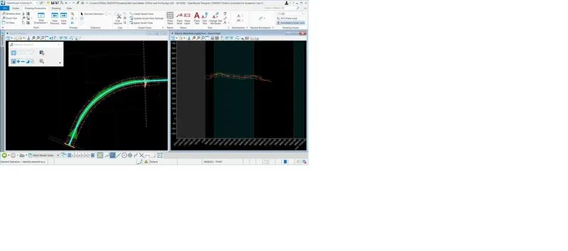
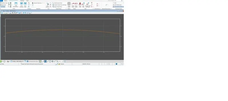
- For creating the profile named boundaries=>go and click on the alignment line(CL)=>flyout menu=>open profile view in a new window
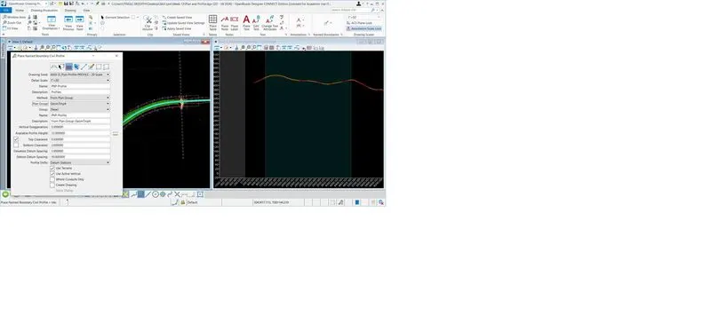
- Now go back to the Named boundaries=>window opens up=>select the profile symbol on top of window and fill out the window as shown below.
- Note: Method should be created as per the requirement which is very important. If the profile named boundary should be created as per the plan named boundaries, then method should be selected as plan groups. Also, the profile shift to be adjusted accordingly.
- Give a data point and profile named boundary has been created.
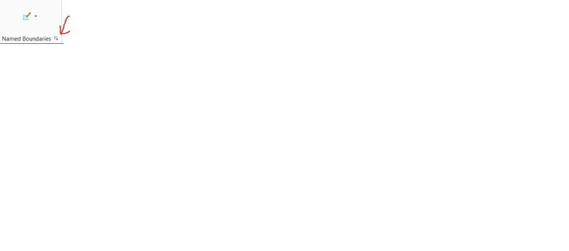
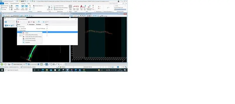
- Now click on the named boundary as shown below, a new window appears
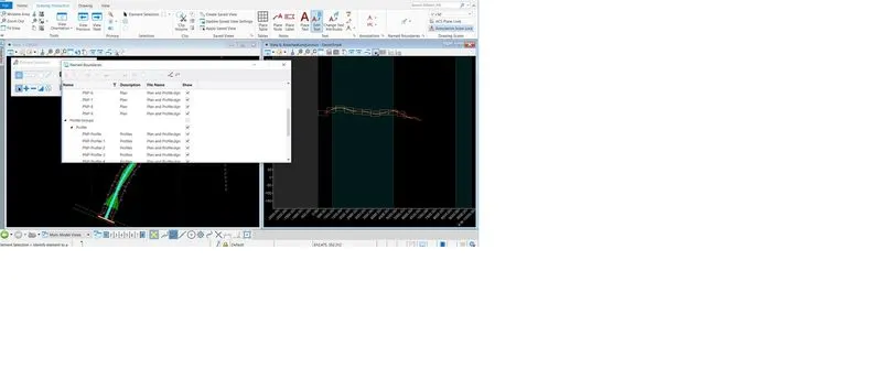
- Check the boxes for plan groups and profile groups.
- All the created drawings are listed below as shown
- Now right click on the plan group or profile group. There is an option pops up to create plan drawing alone or create plan and profile drawing altogether.
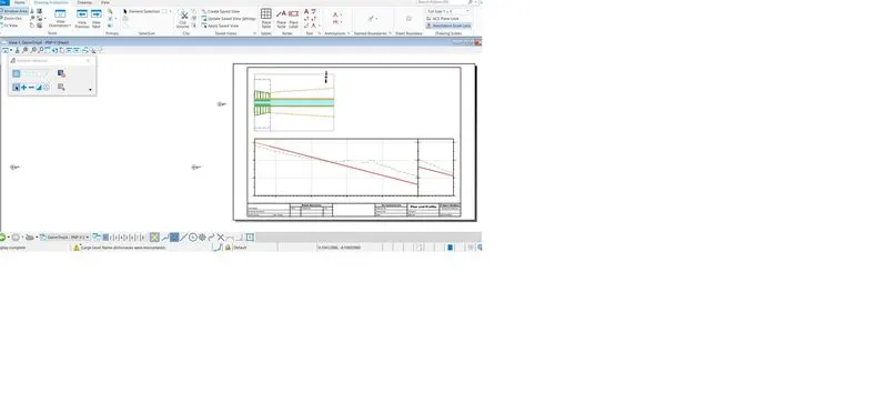
- Now click create plan and profile drawing and the drawings have been generated.
- Stationing can be seen as following and annotations can be done on this drawing.
- Note: rom the reference file the display options can be adjusted in order to disappear the drawing lines.
- Thus, plan and profile sheets can be created
 \
\
4. Create cross sections sheets.
- Open ORD => Training & Examples=>Training Imperial=>attach seed 2D imperial design.dgn=>name the dgn as Cross sections=>attach corridor basics.dgn=>go to level display menu and turn off the heavy layers such as volume cut and volume fill.
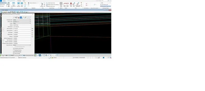
- Go to drawing production Tab=>click on Named boundaries=>select civil cross section boundaries from the wind and fill out the window as below.
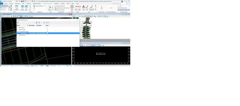
- Click OK and another window pops up=> do a cancel and go to place a name boundary bottom arrow and a new window pops up as seen below.
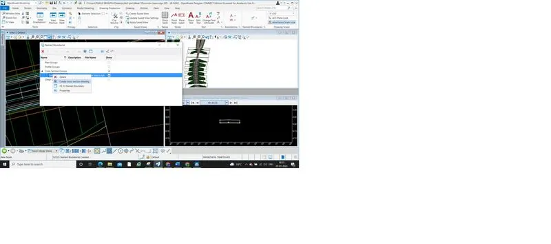
- Now right click on the cross section named boundaries as seen below and select create cross section command.
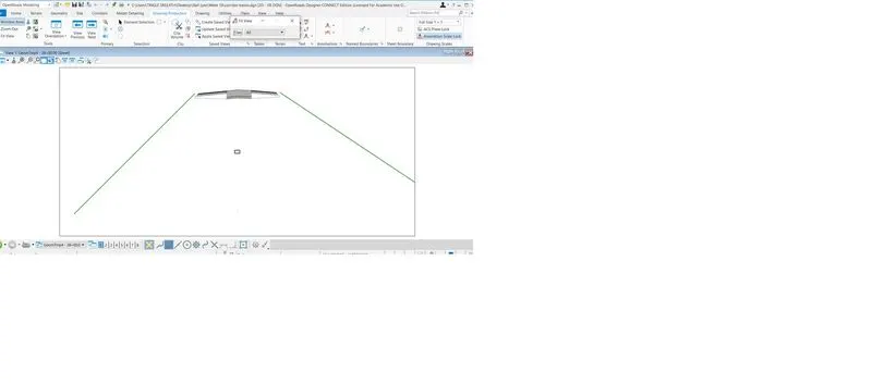
- 52 cross sections have been created as shown below.