Week 12 Challenge
AIM AND INTRODUCTION:
- To calculate the barge impact load of the Panamax vessel, design the bridge for given specifications and apply the calculated load on the bridge using staadpro.
- Barge refers to the ships or vessels crossing the bridges constructed in rivers, canals, sea causes collision on the bridge structure.]
> span arrangement
> Horizontal clearance between the inner piers.
> vertical clearance above aircraft of the bridge to the soffit of the deck.
> minimum depth of water in the channel.
- IRC 6 2017 gives the details for barge impact loads.
- Barge collision energy is given by KE = 500 * CH * W * V^2
- CH is a hydrodynamic coefficient.
- W is barge displacement in tonnage.
- V is barge impact speed.
PROCEDURE :
- KE = 500 * CH * W * V^2
V = 60KM/hr
W = 52500
CH = 1.25
- KE = 500 * 1.25 * 52500 * 60 * 60
KE = 11812500
- We apply the barge load of 11812500 as calculated above on the bridge structure and perform analysis in staad pro.
-
The step by step procedure for the design of the bridge is
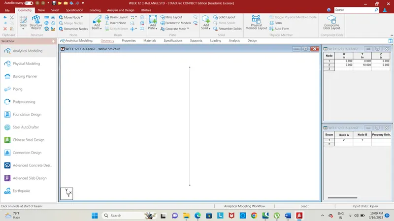
Fig. 1
- First, enter the coordinates for nodes, give coordinates as (0,0,0) and (0,10,0) for the pier, and connect the two nodes by using add beam command.
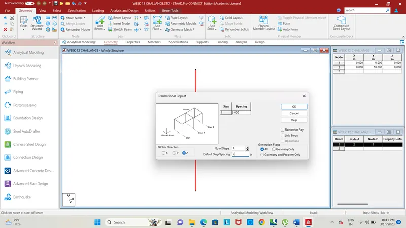
Fig. 2
- Select and copy the pier in z-direction for 1 step at a spacing of 7m, the 7m shows the width, hence the two piers will be created at distance of 7m width of the bridge.
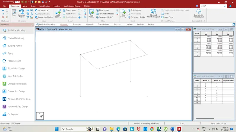
Fig. 3
- Select and copy the two piers in X-direction for a step at a spacing of 12m using translational repeat command, hence another two piers will be created along the span of the bridge at a distance of 12m.
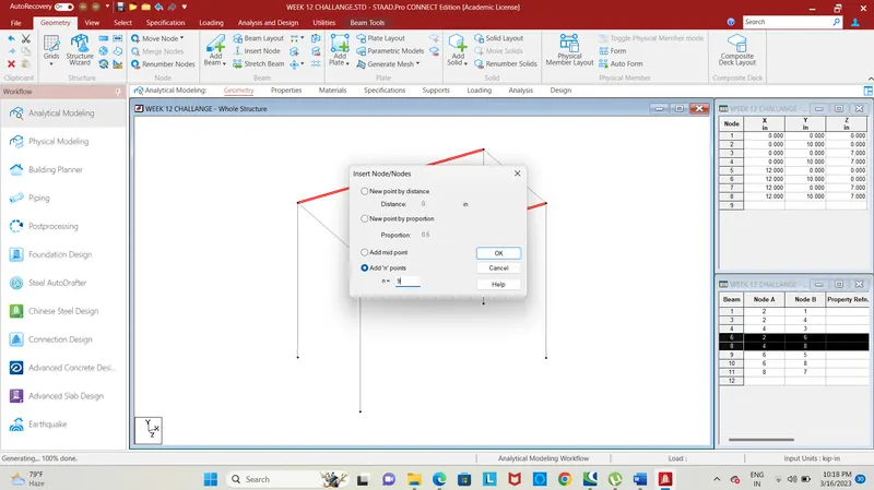
Fig. 4
- Next, we need to add 9 nodes for creating a truss-like section above the deck slab in y-direction, select the longitudinal beams and insert nodes by using insert node button in the geometry section.
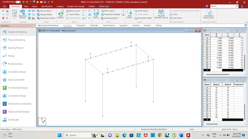
Fig. 5
- Using translational repeat command select the end nodes on both side of the longitudinal beam and repeat them in Y-direction for 1m height link steps, likewise repeat the other nodes in Y-direction for height of 1m additionally from the previous nodes.

Fig. 6
- The node is raised in Y-direction on either side of the central node, the central node will repeat in Y-direction for a height of 5m using translational repeat command.
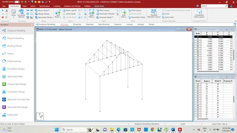
Fig. 7
- The nodes are copied in Y-direction for required height, connect the members using add beam command, thus the structure above the deck slab will be like a truss structure.
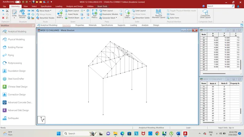
Fig. 8
- Add a midpoint node in the above members and connect the them using add beam command, after creating the truss structure we need to assign sectional properties to the bridge.
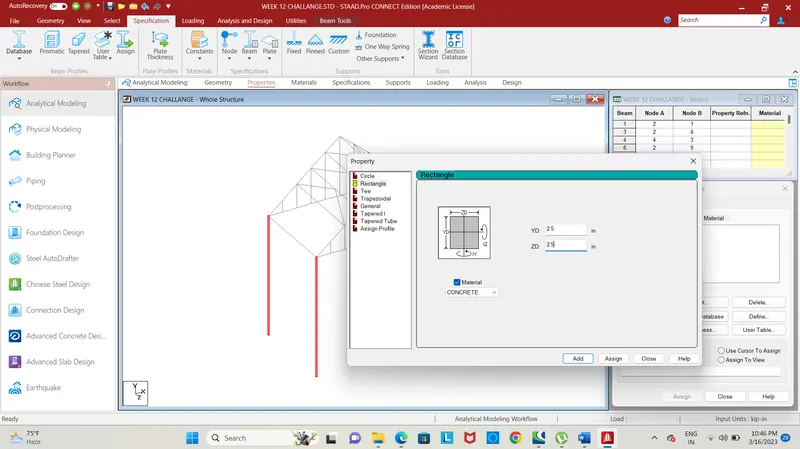
Fig. 9
- Add a rectangular section of size 2.5 * 2.5 of concrete material, select the piers and assign the property to selected piers.
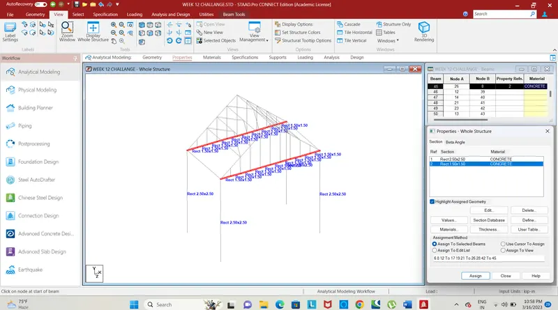
Fig. 10
- Add a rectangular section of dimension 1.5 * 1.5 of concrete material, select the longitudinal beam and assign the property to selected beams.
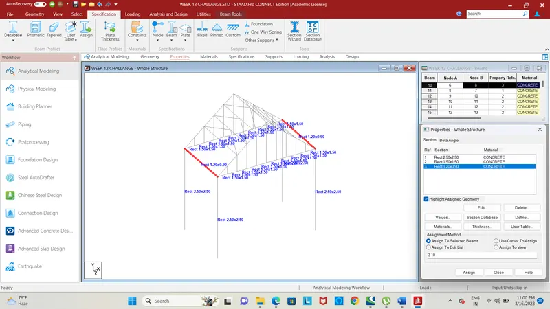
Fig. 11
- Add a rectangular section of dimension 1.8 * 0.75 of concrete material as given in the question, select the cross beam and assign the property to selected beams.
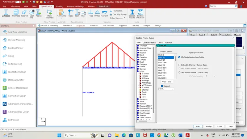
Fig. 12
- Add channel section ISMC 100, select the truss structure raised above deck slab, assign the selected property to the truss structure.
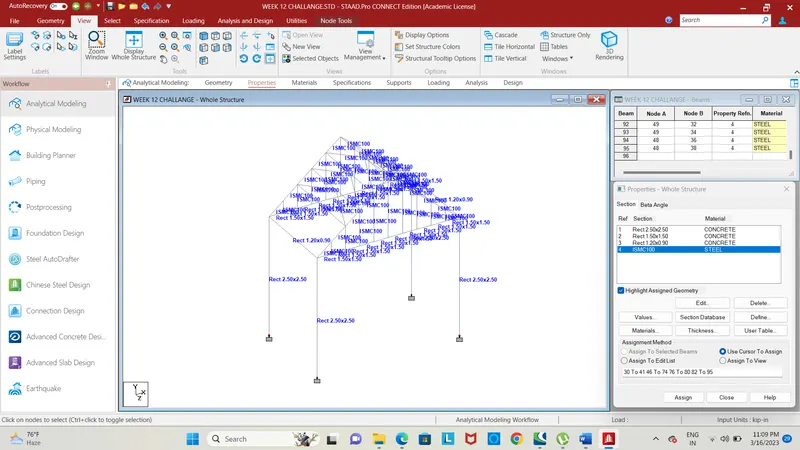
Fig. 13
- Add fixed support, select the nodes of pier and assign the support to selected nodes of piers.
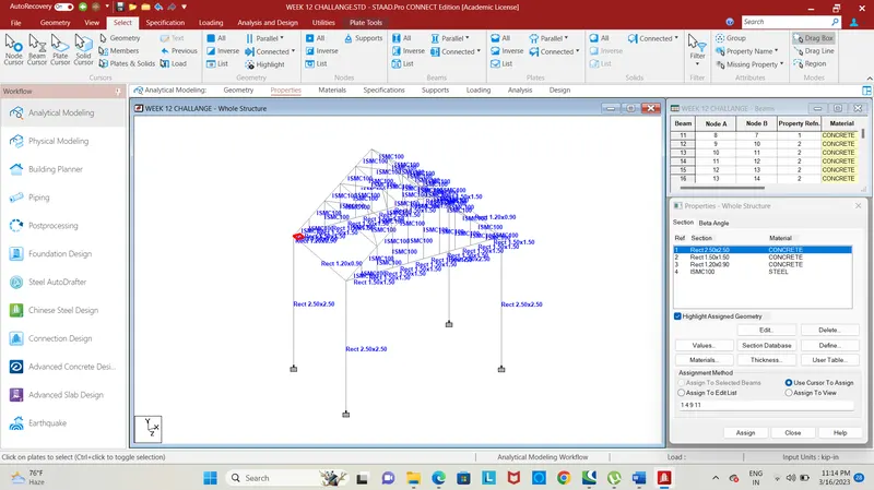
Fig. 14
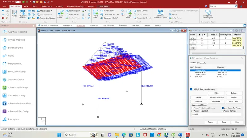
Fig. 15
- The next step is to form a deck to the designed bridge structure, select the corner to repeat them in the x and z direction of spacing 0.5m, create a plate using add plate command, repeat the plate in the x-direction for 23 steps and 13 steps in the z-direction.
- Add a plate thickness of 550m and assign the thickness to deck plates.
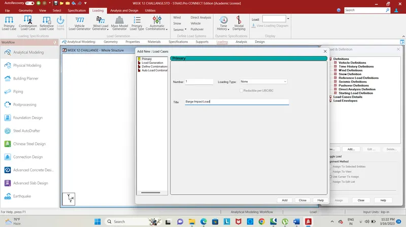
Fig. 16
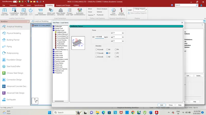
Fig. 17
- The next step is to give loading to the structure, add a new load in load case details and give title as barge impact load, add a calculated load as a member load.
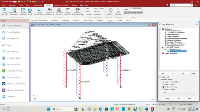
Fig. 18
- After adding load, click on global z-direction and select the piers to apply the calculated load.
RESULT :
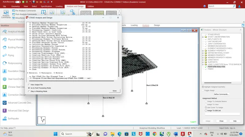
Fig. 19
- After loading click on the run analysis command for analysis of the structure, then enter into post-processing mode.
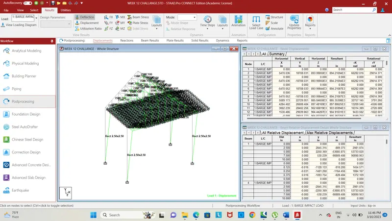
Fig. 20
- The fig shows the deflection pattern of the bridge structure due to barge impact load in the postprocessing mode, click on deflection tab.
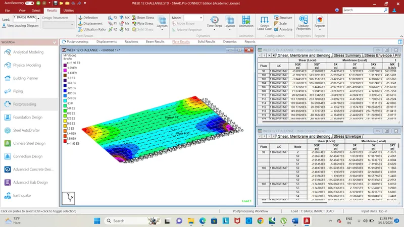
Fig. 21
- Click on the plate stress and select My for given loading, the stress diagram will be displayed in contour image, showing the stress values at the plate.
- Hence the bridge is designed and analyzed for the given loading.