Week 12 Challenge
Design of Foundation in STAAD Foundation
1. Isolated Footing
Design isolated footing for a column 300 mm x 450 mm, carrying axial load of 1500 kN and Mu = 150 kNm using STAAD. Foundation. Assume that the moment is reversible. The safe bearing capacity of the soil is 200 kN/m2 at a depth of 1 metre from ground level. Use M 25 and Fe 415 for the footing. Also validate the design through hand calculation.
Solution:
Aim: We need to design Isolated Footing Design using STAAD Foundation for the given data:-
Size of column : 300 mmx 450 mm
Axial load : 1500 KN
Moment MuMu : 150 KNm ( Reversible)
SBC of soil : 200 KN/m2m2 at a depth of 1 m from ground level
Grade of concrete : M25
Grade of steel : Fe 415
Design is also to be validated through hand/manual calculation
Procedure:
- Open the Staad Foundation and click on General Design to start the design of combined footing.
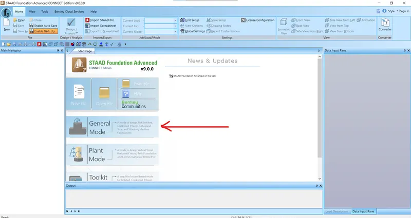
- A new working window will appear.
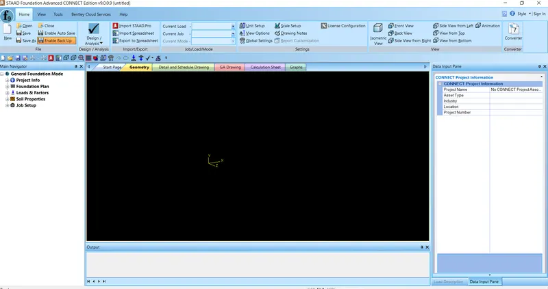
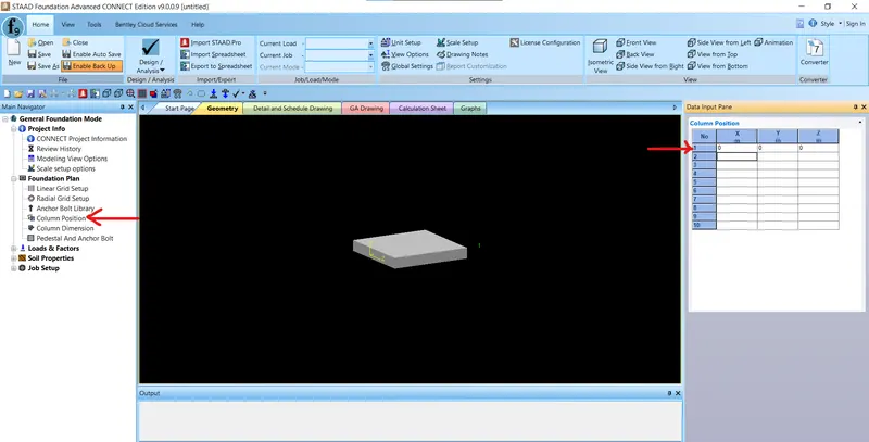
- Now, we will enter the support coordinates for the Isolated Footing. Let the footing coordinates be at origin.
- To place the footing, go to Column Position and enter the coordinates as (0,0,0) as shown in below figure.
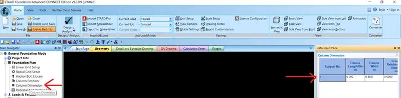
- Now, we will the column dimensions as given 300 mm x 450 mm as shown in below figure.
- Now, we will add the load, for that go to Load and Factors Option on the Main Navigator panel.
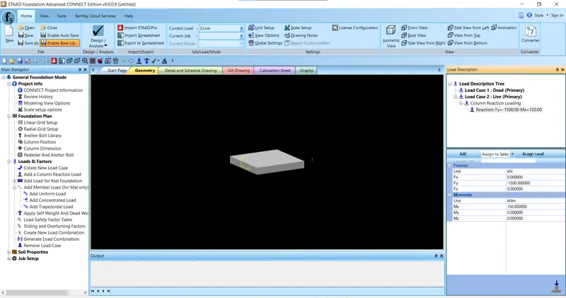
- Choose the Create New Load Option to create the load cases for Dead Load and Live Load, also add the given load condition of Fy = -1500 kN and Mx = 150 kNm as shown in below figure.
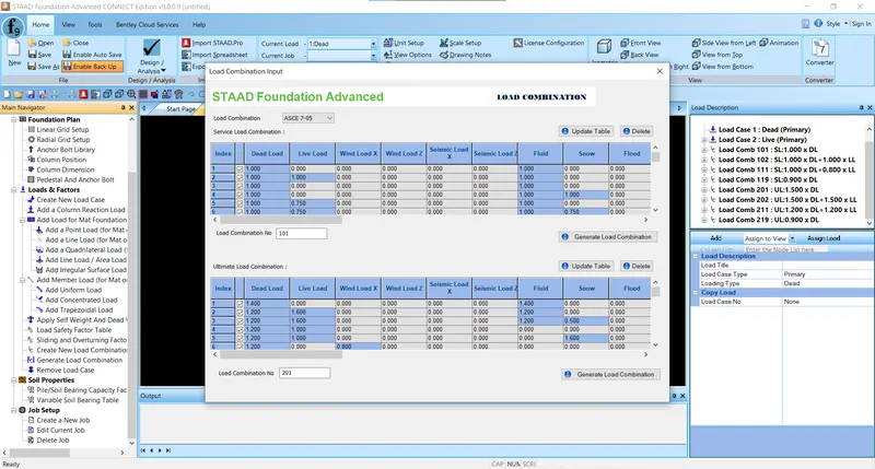
- Now we will generate the load combination cases as per Indian Code.
- Now we will create the job info to analyse and design the footing.
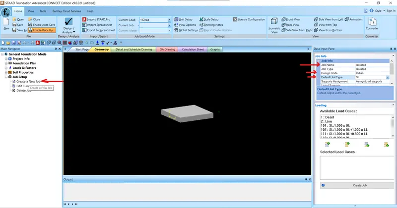
- Now, a job has been created for the isolated footing as shown in below figure.
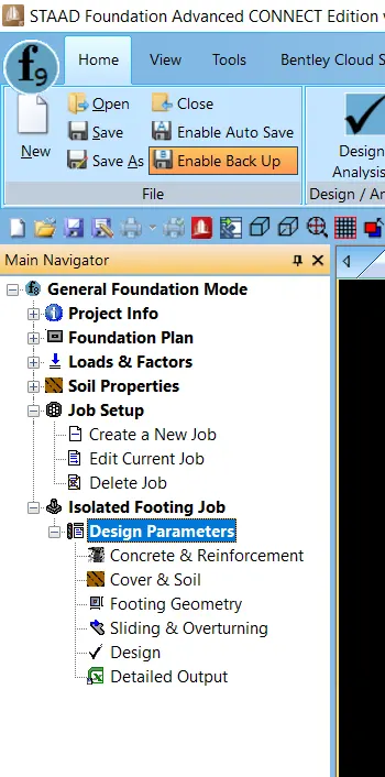
- Now we will fill the data for the design of the footing as given.
Safe Bearing Capacity = 200 kNm2kNm2 at depth of 1.0 m from Ground Level.
Grade of Concrete = M25
Grade of Steel = Fe415
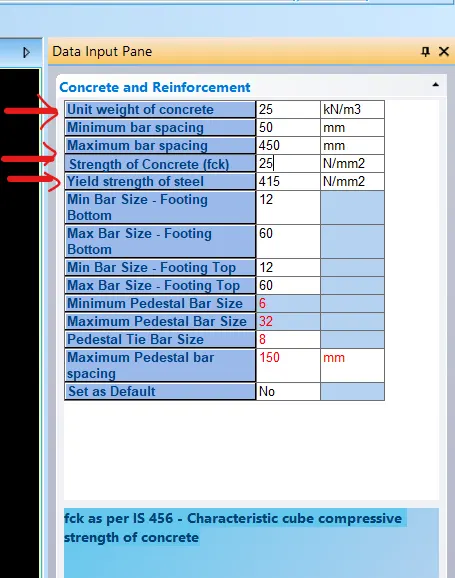
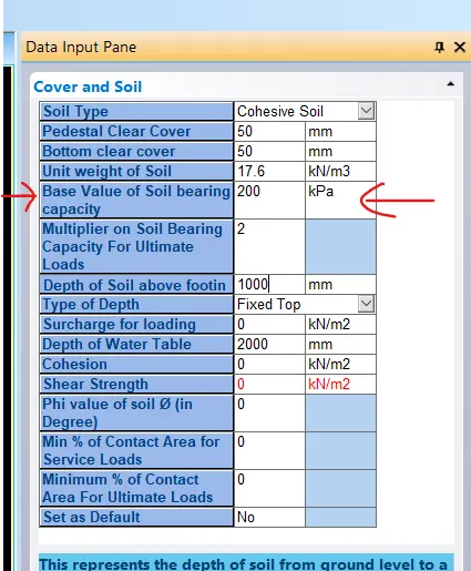
- Now, after entering the data, click on the Design option to analyze and design the Footing as shown in below figure.
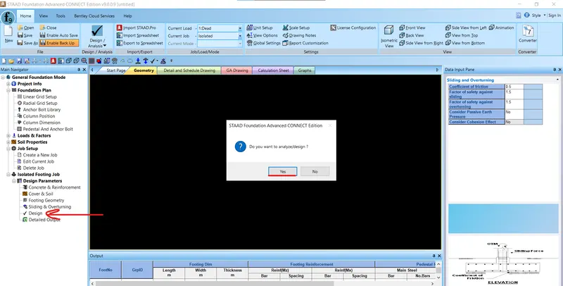
- Click on YES to start the Design Process.
- Design of the Footing has been done succesfully.
Following design result has been found out:
- Dimension of footing:3 mx 3 m
- Over all depth of footing D = 650 m
- Depth of footing is checked for BM, Single shear & Double shear and found safe
- No tension steel is needed as there is no negative pressure.
- Development length = 648 mm
Now,for validation of design of footing using hand calculation.
VALIDATION OF DESIGN THROUGH HAND CALCULATION
Footing should be symmetric with respect to column as the moment is reversible( Mx&MyMx&My are same ,that is square footing is to be designed.
Service load = 1500KN
Considering Self weight of footing & weight of backfill soil = 10% of service load
P = 1.1x 1500= 1650 KN
PuPu= 1.5x1650KN = 2475 KN
Area required = 1.1PSBCPSBC = 1.1x1500/200 = 8.25 sqm`
Acal=8.25m2Acal=8.25m2
Therefore L=B=√A=√8.25=2.87mA=8.25=2.87m
`provide square footing of size 3.0 m x 3.0 m
Aprovided=9m2Aprovided=9m2 > Area required which is 8.25 sqm (OK)
STEP-2 : NET UPWARD SOIL PRESSURE
σ(max,min)=PdAprovided+MuZσ(max,min)=PdAprovided+MuZ
= (1.5x 1.1x1500/9) ±±( 1.5x150/(B×L2/6)(B×L2/6) ( B=L=3 M)
= 275±±50
σ(max)σ(max)= 325 KN/ sqm < 370 KN/sqm ( Gross factored Bearing capacity) ( ok)
σ(min)σ(min)= 225 KN-m < 340 KN/sqm
Eccentricity e = M/P = 150/1500 = 0.1M = 100 mm
L/6= 3000/6 =500 mm
e < L/6 ,therefore no negative soil pressure will develop hence compression steel is not required.
STEP-3 DEPTH OF FOOTING ON THE BASIS OF B.M.
The maximum bending moment at the face of column (M)
= P0×(B−b)2/8P0×(B-b)2/8 = 275×3(3−0.3)2/8275×3(3-0.3)2/8= 751.78 KNm
Mu=0.138fckbd2Mu=0.138fckbd2
751.78×106×106 = 0.138x20x3000xd2d2
d = 301 mm Say d = 305 mm
Adopt d = 600 mm due to shear consideration
Add effective cover = 50 mm
D = 650 mm
Depth of footing from one way shear-
d= Pu(L−a)2(P+τc×L2)Pu(L-a)2(P+τc×L2)
= 1.5X1.1X1500( 3-0.3)/2(1.5x1.1x1500+350x9)
= 6682.5/11250 =0.594 m = 594 mm < 600 ( OK)
Depth required for two way shear ( punching shear)
PL2[L2−(a+d)2]=4(a+d)d×τpPL2[L2-(a+d)2]=4(a+d)d×τp
[1.5x1.1x15009][(9−(0.3+0.6)2]1.5x1.1x15009][(9-(0.3+0.6)2]= 4x0.9 x0.6τpτp
τpτp= 1043.98 KN/m^2 = 1.044 N/mm2mm2
Permissible τpτp= 0.25√fckfck
=0.25 √2020
= 0.25x4.472 = 1.118 N/mm2mm2 > 1.044N/mm2mm2 ( OK)
STEP-4: Reinforcement calculation
Ast=0.5fckfy[1−{1−(4.6×Mu/fckBd2)Ast=0.5fckfy[1-{1-(4.6×Mu/fckBd2)
AstAst= 5081 sqmm
p = AstB×d×100AstB×d×100
= (5081/3000x650)x100 = 0.26% > 0.12% which is min reqr , hence OK
xud=1.2−[1.44−6.6Mufck×b×d2]12xud=1.2-[1.44-6.6Mufck×b×d2]12
=1.2−[1.44−(6.6x751780x100020x3000x600x600)0.5=1.2-[1.44-(6.6x751780x100020x3000x600x600)0.5
= 0.0998
Lever Arm Z = d(1-0.416xud)xud)
= 600( 1-0.416x0.0998)
= 575.089 mm
Ast=Mu0.87×fy×ZAst=Mu0.87×fy×Z
= 751780X1000/0.87X415X575.089 = 3620.66 mm2mm2
STEP-5 : DEVELOPMENT LENGTH
As per IS 456: 2000,Cl 26.2.1.1
σs=415Nmm2σs=415Nmm2
τbdτbdfor deformed bar and M20 Grade of concrete = 1.92 N/mm2mm2
Ld=ϕ×σA4τbdLd=ϕ×σA4τbd
415ϕϕ/4x1.92 = 54ϕϕ = 54x12 = 648 mm for 12 mm dia bar.
Result: Isolated Footing for the given data has been designed succesfully using STAAD Foundation and summary of the design is as follow:
- Dimension of footing: 3 mx 3 m
- Over all depth of footing D = 650 mm
- Depth of footing is checked for BM, Single shear & Double shear and found safe
- No tension steel is needed as there is no negative pressure.
- Development length = 648 mm.
2. Combined Footing
Design a combined footing using STAAD. Foundation for two columns C1, 400 mm x 400 mm carrying a service load of 800 kN and C2, 300 mm x 500 mm carrying a service load of 1200 kN. The column C1 is flushed with the property line. The columns are at 3.0 m c/c distance. The safe bearing capacity of soil is 200 kN/m2 at a depth of 1.5 m below the ground level. Use M 20 and Fe 415 for columns and footing.
Solution:
Aim: We need to design Combined footing for given data:-
1. Two columns C1 & C2 having size 400 mmx 400 mm & 300 mmx 500 mm respectively.
2. Service load on C1 is 800 KN & on C2 is 1200 KN
3. Column C1 is flushed with property line
4. C/C distance between columns = 3.0 m
5. SBC of soil = 200 KN/m2m2 at a depth of 1.5 m
6. Grade of Concrete : M20
7. Steel grade : Fe 415
Procedure:
- Open the Staad foundation software,click on general mode.
- Now we will enter the Support Coordinates to place the columns.
- Column C1 & C2 are placed at a distance of 3 m and their dimensions are 400 mmx 400 mm & 300 mm x 500 mm respectively as shown in below figure.
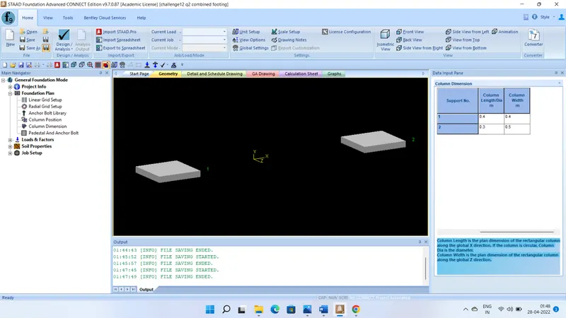
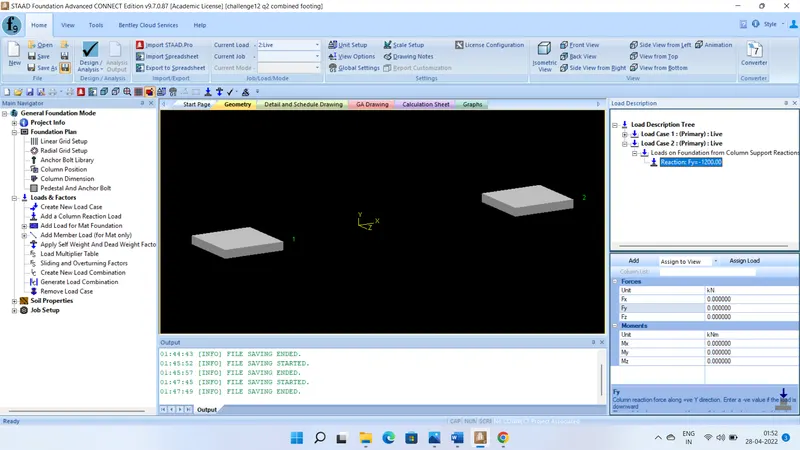
- Two primary load cases as Live load as per given input have been created as shown in below figure.
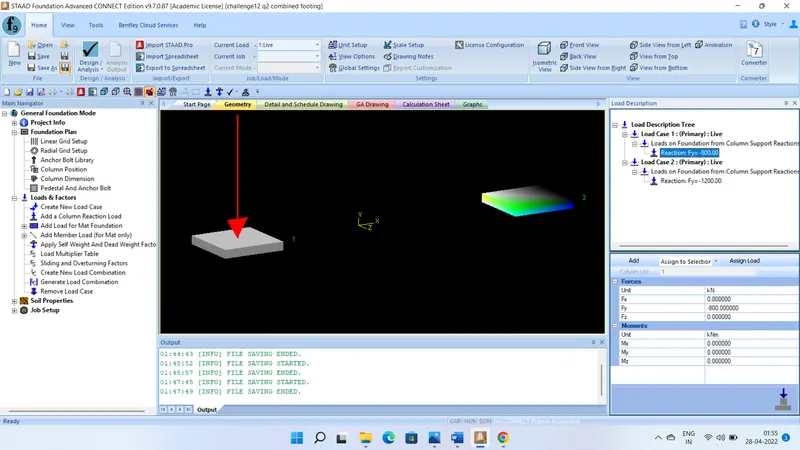
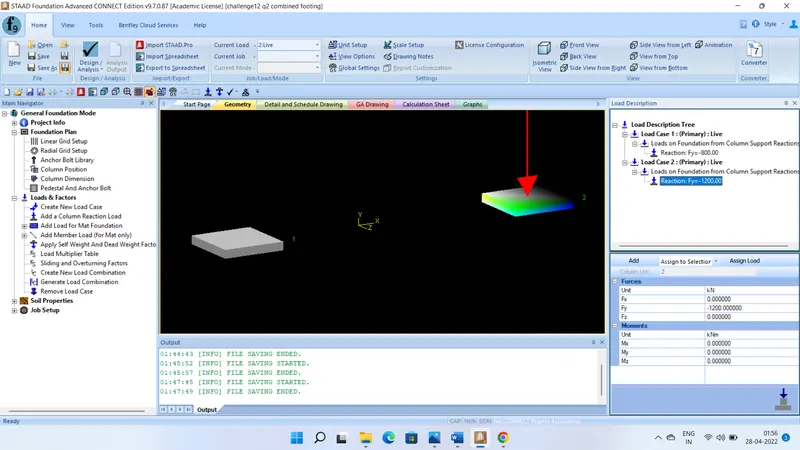
- Assigning load of 800 KN on C1 & 1200 KN on C2 as shown in below figure.
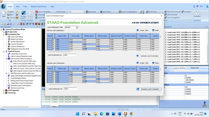
- Now, we will generate load combination as shown in below figure.
- After assigning the Load Combination, we will create the Job Setup.
- Keep the following points i.e, Design Code should be Indian, and Units should be in SI unit.
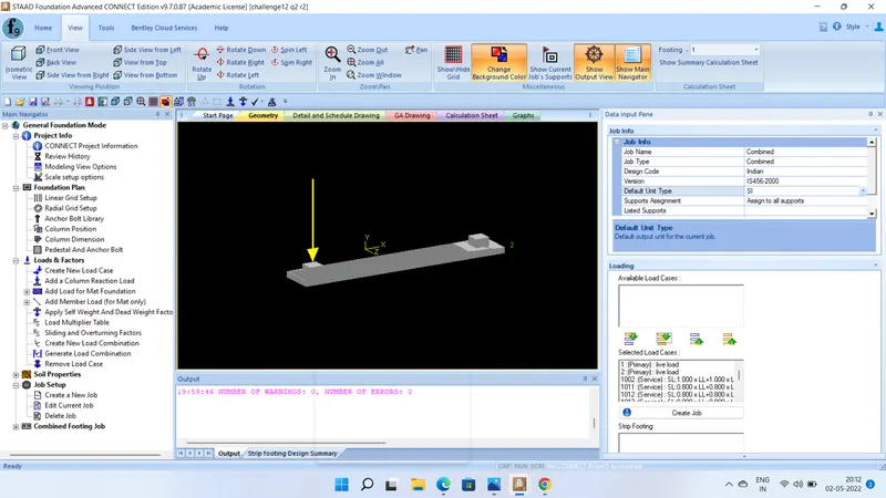
- Edit current job under job set up then create strip footing after selecting both columns as shown in below figure.
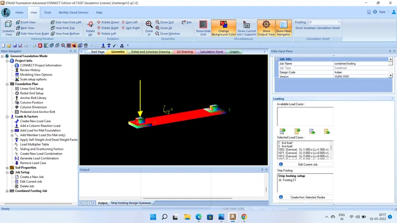
Under combined footing job we have to assign the following parameters:
- Unit weight of concrete
- Max. and min. spacing of bar
- Strength of concrete = M20
- Yield strength of steel= 415 Nmm2Nmm2
- Min. & Max. bar size
- Clear cover of pedestal & footing
- Unit weight and Safe Bearing Capacity(SBC) of soil
- Depth of soil above footing
- Min % of contact area for service load
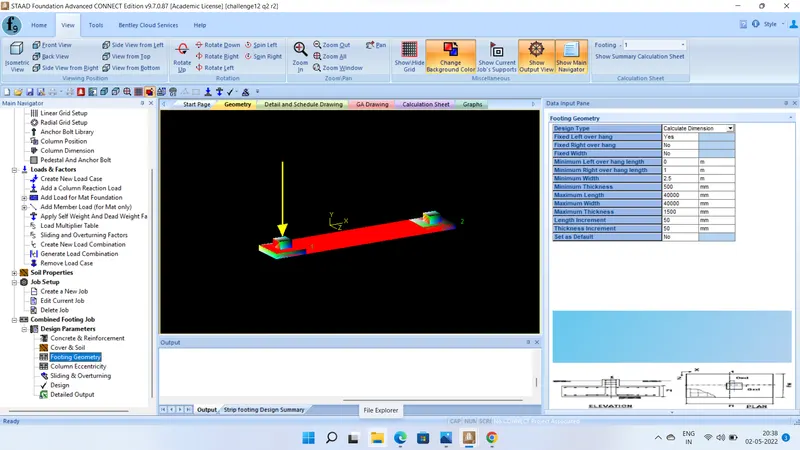
- Footing geometry such as overhang, min width, max length, width, max- min thickness, length and thickness increament etc. as shown in below figure.
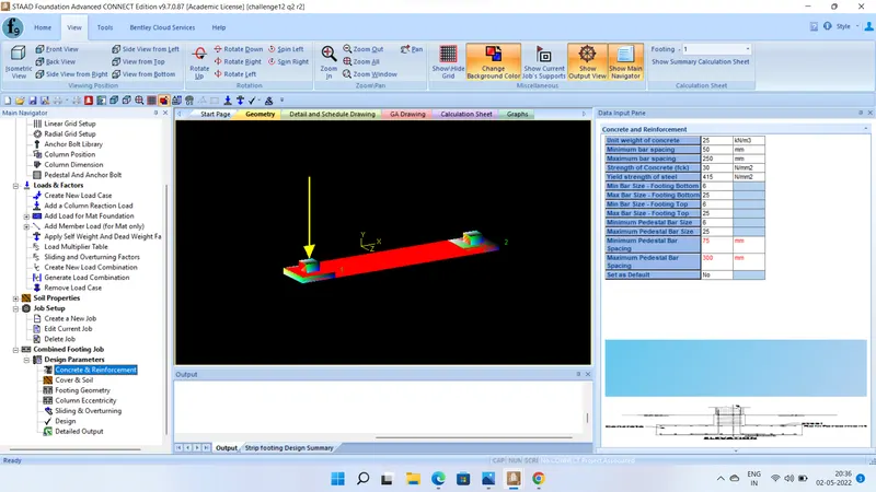
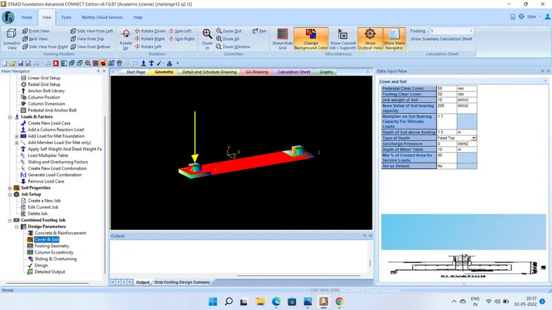
- Now, we will click on Design command to obtain the design of the Combined Footing.
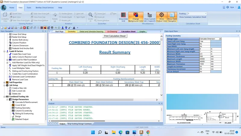
RESULT: It is concluded that-
- Design is successful with footing dimension as 9.2m x 7.5 m and thickness 0.5 m.
- C-1 column is flushed with property line that is left over hang is 0.
- Main steel top 8mm dia bar @ 50 mm c/c
- Main steel bottom 8 mm dia bar @ 55 mm c/c
- Secondory steel bottom 12 mm dia 60 mm c/c and top 8 mm dia 80 mm c/c
- Design is safe against sliding , single shear , punching shear, soil pressure, overturning.
Hence, design of Combined Footing has been done succesfully.