Introduction to REVIT concepts
1) Aim: To create a new project(Structural/ Architectural/ Construction template) from the file menu and name the project accordingly
Procedure:
1. To create a new project, click on the file icon on top left of the interface.
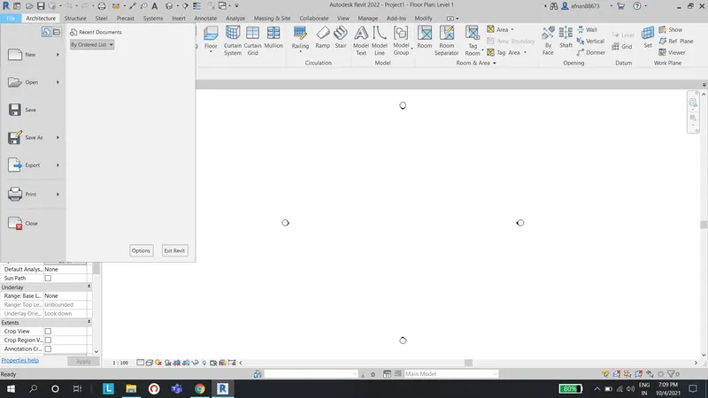
2. Then click on "New" and then "project".
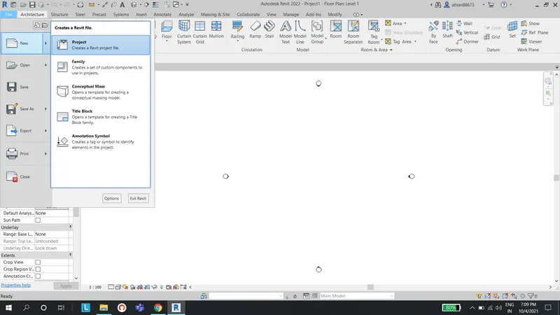
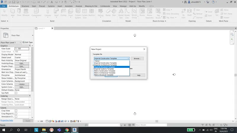
3. Select the template file you want and click 'OK'.
4. Name the project accordingly from 'save as' option and then project and then 'save'.
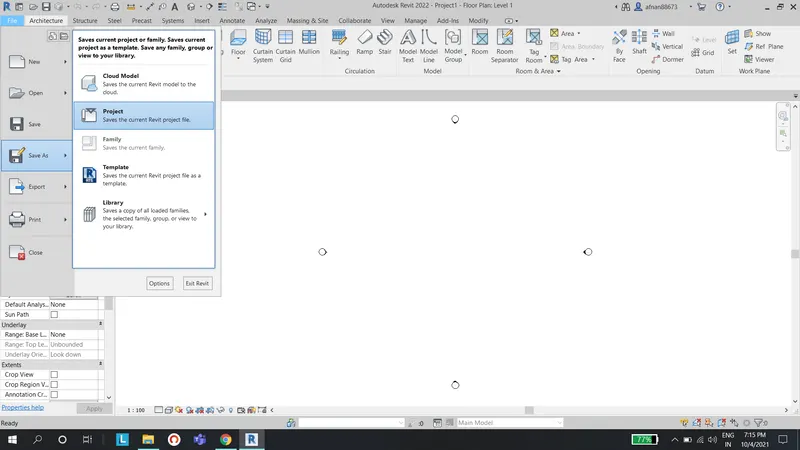
Result: New file is created.
2) Aim: Save the new project file. Close and open using icons from file toolbar.
Procedure:
1. Open a new file and click on file menu
2. Click on 'save as'
3. Name the project and save it.
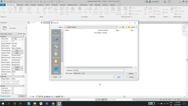
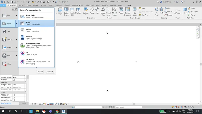
4. To open the file goto file and then 'Open', select the project and then Open.
5. To close the file goto file and then 'close'
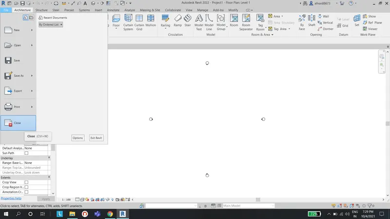
Result: The file is opened, saved and closed.
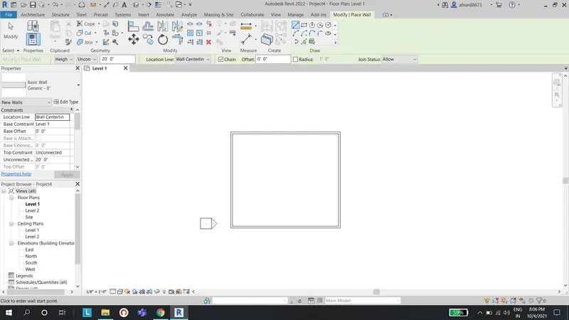
3) Aim: To familiarize with options to draw a wall. Create a rectangular layout of walls of about 40’-0” X 35’-0”
Procedure:
1. To draw a wall, Go to architecture section, and select wall.
2. Select the type of wall you want to draw(architectural/structural)
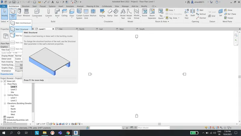
3. After selecting the type of wall place your cursor on workspace, draw the walls making a rectangular layout of 40' x 35'. you can type in the values for measurements (make sure you have selected the Imperial-architectural template for feet-inches)
Result:
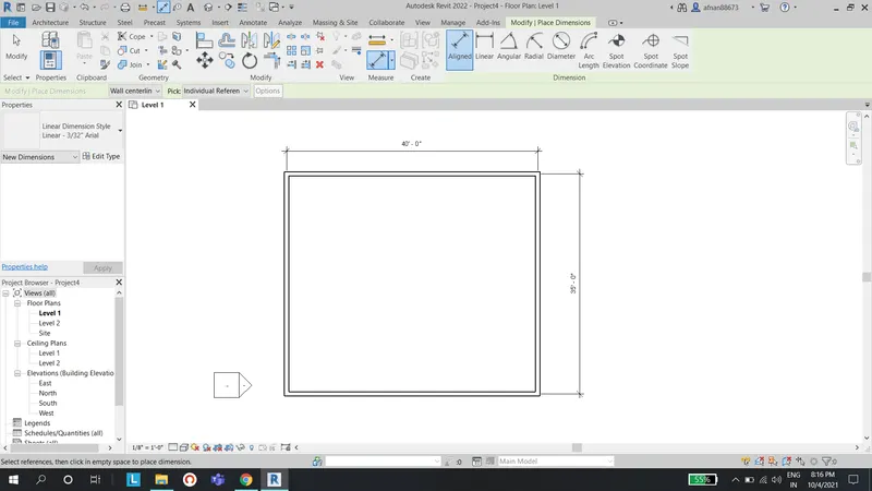
4) Aim: To use the aligned option from the Annotate toolbar to add dimensions to the layout
Procedure:
1. Go to annotate menu and select the aligned dimension.
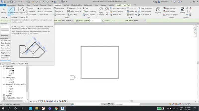
2. Use the reference of horizontal and vertical lines to mark the dimensions.
Result:
5) Aim: To use the properties browser to switch to different wall types
Procedure:
1. Select the walls in the workspace using your cursor.
2. Go to the properties browser to the leaft side of the screen
3. You can switch to any wall type you intend to
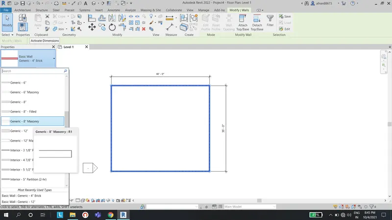
Result: The desired wall type is achieved.
6) Aim: To create a 3D view from the view toolbar and save the view with the appropriate name
Procedure:
1. Go to the 'View' toolbar and select the default 3D view
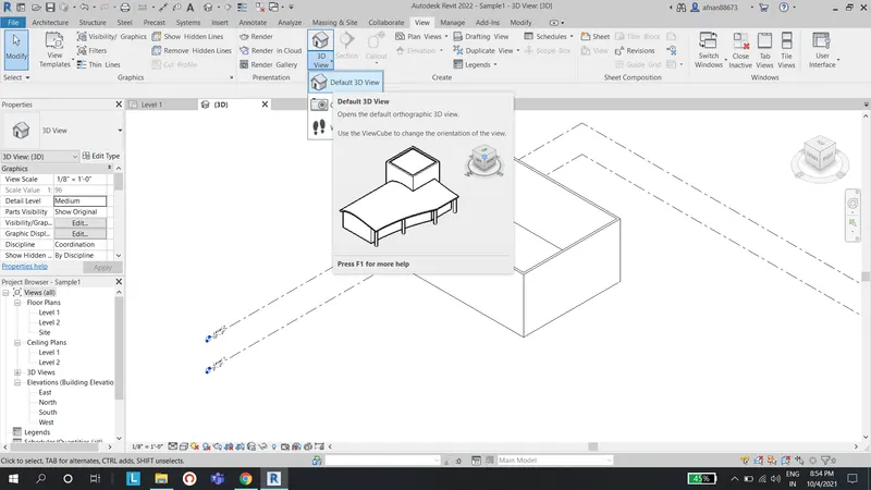
2. To save the 3D view, right click on viewcube and click on save view, name it accordingly.
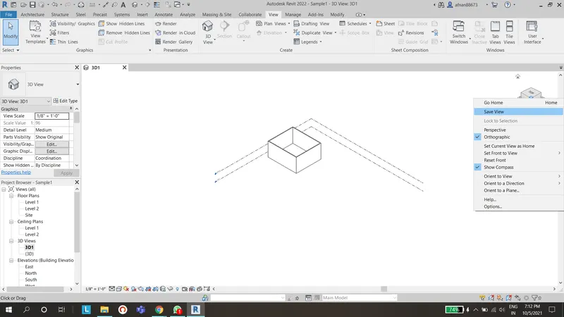
Result: The 3D view has been saved.
7) Aim: To navigate through the 3D model using the view cube. Orbit/pan through the model layout created
Procedure:
1. To navigate using view cube, simply left click on view cube and rotate it to see the front,back,right,left and top views.
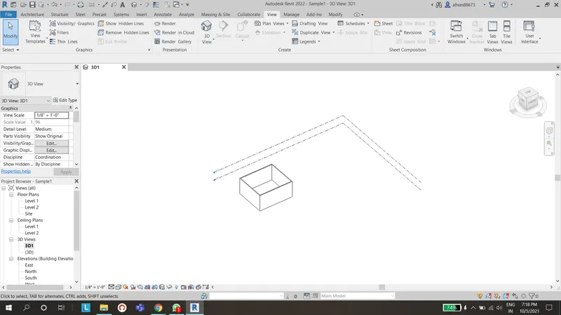
2. To orbit through the model, select the full navigation wheel and select orbit and you can orbit through the model
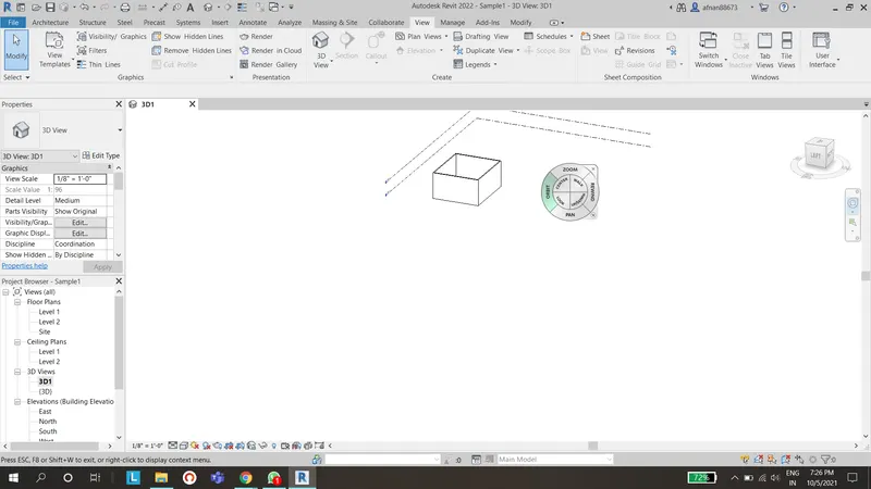
3. To Pan through model space, select the navigation wheel and select pan.
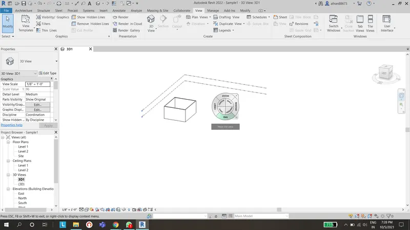
Result: The model is navigated and Orbit/Pan tools are used successfully.
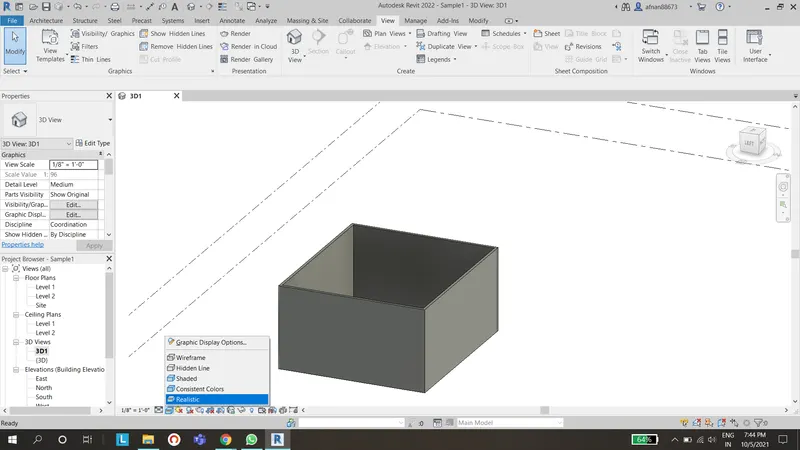
8) Aim: To use the visibility settings option below to switch model to shaded, realistic, hidden lines options
Procedure:
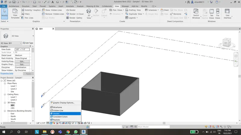
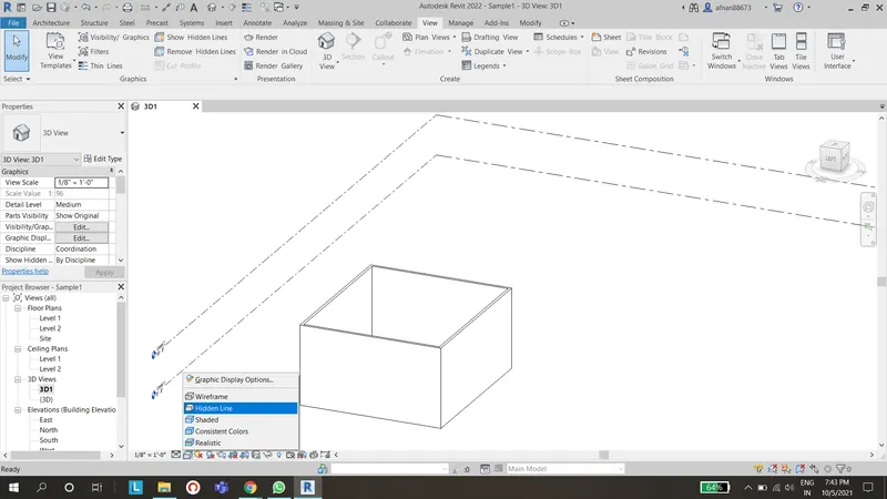
1. Select the visibility settings present at the bottom of the screen(second from left)
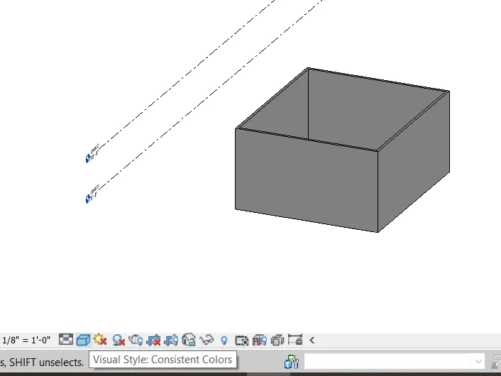
2. Select the visual style to shaded/realistic/hidden lines.
Result: The visual styles are achieved.
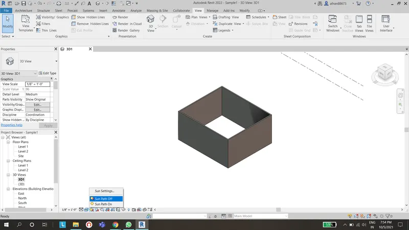
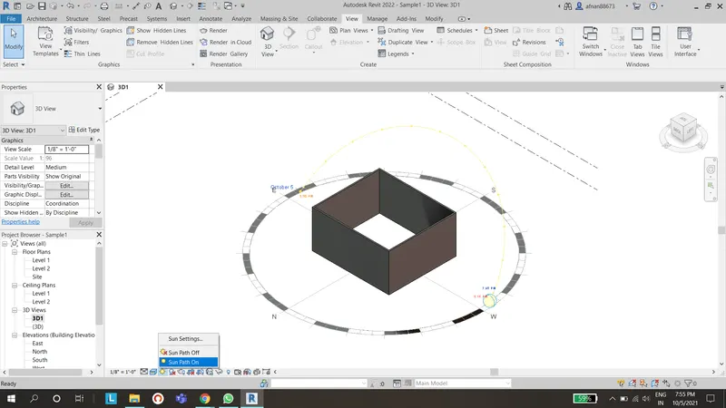
9) Aim: To turn the sun path on and off to view shadings in the layout created
Procedure:
1. Click in sun symbol present at the bottom of the screen.
2. Turn on the sun path
3. Go to sun settings and select still, and then Ok.
Result:
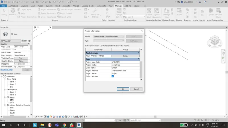
10) Aim: To use the Manage toolbar to enter project settings, project name, and project issue date
Procedure:
1. Click on manage toolbar and select the project information
2. Enter the project date,name, status, issue date accordingly
Result:
11) Use of analyse toolbar in Revit and its benefits for design and modelling:
Analyse toolbar helps you to perform analysis on our structural building. The boundary conditions enable you to define point line and area boundary conditions in an analytical model. It will verify the boundary condition family types are loaded and assigned in your parametric features of the structural model, Similarly we can apply point load to a model to evaluate the performance of the building.
12) Links that Revit supports to be linked to the model:
LINK REVIT: This allows to link another revit model to the current model, Eg: we can link models together to specify the relative individual building on a campus or to coordinate efforts across disciplines (architectural, structural, mechanical)
LINK IFC: To link IFC file to current model to reference its information for additional design work.
LINK CAD: To link the 2d cad file to current revit file to create 3d by revit tools.
MANAGE LINKS: Provides feature to manage the links to the building models. for example: If we are linking the electrical and structural model to remove electrical from structural, go to link manager and unload the model we dont want.
13) Revit provides several different ways to collaborate with team members who are also software. You can link multiple Revit models together, allowing team members to work in context.
Through worksharing, users on the same local area network (LAN) can work together in the same Revit model.
When collaboration needs to occur among users who are not in the same geographic location, use Revit Server or Revit Cloud Worksharing.
Revit Server connects offices who share a network but are not in the same geographic location.
Revit Cloud Worksharing is a cloud-based service that allows any Revit users inside or outside a network to collaborate on a Revit model.