Week 11 - Simulation of Flow through a pipe in OpenFoam
Simulation of Flow through a pipe in OpenFoam
In this challenge, you will simulate an axis-symmetric flow by applying the wedge boundary condition. The flow is laminar and flows through a constant cross-section pipe at an inlet Reynold's number of 2100. You can do a transient or steady state simulation and you will validate your results with Hagen- Poiseuille's equations for the fully developed flow.
Hagen Poiseuuiles Equation
The Hagen-Poiseuille equation, also known as the Poiseuille law, Poiseuille equation, or Hagen-Poiseuille law, is a physical law that determines the pressure drop in an incompressible and Newtonian fluid flowing through a long, cylindrical pipe with a constant cross-section.
The equation assumes that the fluid is incompressible and Newtonian, that the flow is laminar in a pipe with a constant circular cross-section that is significantly longer than its diameter, and that there is no fluid acceleration in the pipe. The Hagen-Poiseuille equation predicts laminar fluid flow for velocities and pipe diameters below a certain point, but the actual fluid flow is turbulent, resulting in larger pressure drops.
In standard fluid-kinetics notation
`Delta p = (8 . mu. L ⋅ Q )/(A^2)`
where,
`Delta p` is the pressure difference between the two ends,
L is the length of the pipe.
`mu`is the dynamic viscosity.
Q is the voluneru=ticc flow rate.
A is the cross-section of the pipe.
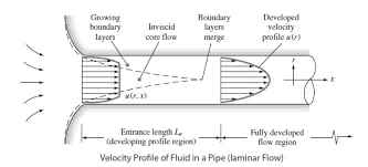
The boundary layer is the one where there are significant shearing viscous forces. This boundary layer is just a speculative idea. It divides the pipe's flow into two areas:
- Boundary layer region: The area where significant velocity changes and viscous effects occur.
- The region of an irrotational flow also called the inviscid core, is where viscous effects and velocity changes are minimal. The boundary layer gradually fills the entire pipe as soon as fluid first enters it, starting at zero and moving in the direction of the flow of the fluid. The length of the pipe in this region is referred to as the hydrodynamic entry length, and this region extends from the pipe's entrance to the point where the boundary layer covers the entire pipe. The flow is referred to as hydrodynamically developing flow in this area where the velocity profile develops. The velocity profile continues unaltered after this region, where it is fully developed. The term "hydrodynamically fully developed region" refers to this area.
Given:
Reynlods number : 2100
temperatue= `25 ^o C`
dia of pipe=0.02m
`mu =0.89 xx 10^(-3)`
`nu =0.89 xx 10^(-6)m^2 s^-1`
`Delta p=(32.mu⋅L⋅Vunderset(avg)())/D^2`
`theta = 4^o`
length=2.52m
Analytical Solution:
- average velocity: `Vunderset(avg)()=(Re⋅mu)/(rho⋅D)=0.0937 ms^-1`
- Maximum velocity:`Vunderset(max)()=2⋅Vunderset(avg)()=0.1875ms^(-1)`
- Pressure velocity:16.8176pa
- Kinematic Pressure Drop:`(Delta p)/rho`=0.0169m.
matlab code for the blockmesh file
clear all
close all
clc

%wedge angles and inputs.
theta = input('Enter the value of wedge angle=');
Re =2100;
D=0.02;
L=0.06*Re*D;
R=D/2;
mu=0.89e-3;
rho=997.0;
nu=mu/rho;

%pressure and  velocity
v_avg=Re*mu/(D*rho);
v_max=2*v_avg;
del_P =(32*mu*v_avg*L)/(D^2);
kin_P=del_P/rho;

n1=50;
n2=1;
n3=300;
gfactor=0.5;

%vertices of the wedge
V0=[0 0 0 ];
V1=[0 R*cosd(theta/2) -R*sind(theta/2)];
V2=[0 R*cosd(theta/2)  R*sind(theta/2)];


V3=[L 0 0 ];
V4=[L R*cosd(theta/2) -R*sind(theta/2)];
V5=[L R*cosd(theta/2)  R*sind(theta/2)];

%printing the contents of blockmesh file


fblock=fopen('blockMeshDict.txt','wt');

fprintf(fblock,'%s\n','convertToMeters 1;');
fprintf(fblock,'\n');

fprintf(fblock,'\n vertices');
fprintf(fblock,'\n (');
fprintf(fblock,'%s\n (%f %f %f)',blanks(5),V0(1),V0(2),V0(3));
fprintf(fblock,'%s\n (%f %f %f)',blanks(5),V1(1),V1(2),V1(3));
fprintf(fblock,'%s\n (%f %f %f)',blanks(5),V2(1),V2(2),V2(3));
fprintf(fblock,'%s\n (%f %f %f)',blanks(5),V3(1),V3(2),V3(3));
fprintf(fblock,'%s\n (%f %f %f)',blanks(5),V4(1),V4(2),V4(3));
fprintf(fblock,'%s\n (%f %f %f)',blanks(5),V5(1),V5(2),V5(3));
fprintf(fblock,'%s\n',');');
fprintf(fblock,'\n');


fprintf(fblock,'blocks');
fprintf(fblock,'\n (');
fprintf(fblock,'%s %s \n',blanks(5),'hex(0 1 2 0 3 4 5 3 ) (50 1 200) simpleGrading (0.5 1 1)');
fprintf(fblock,'\n );');
fprintf(fblock,'\n');

fprintf(fblock,'\n edges');
fprintf(fblock,'\n (');
fprintf(fblock,'%s\n arc 1 2 (%f %f %f) ',blanks(5),0,R,0);
fprintf(fblock,'%s\n arc 4 5 (%f %f %f) ',blanks(5),0,R,0);
fprintf(fblock,'\n );');
fprintf(fblock,'\n');

fprintf(fblock,'\n boundary');
fprintf(fblock,'\n\t (');
fprintf(fblock,'\n\t\t inlet');
fprintf(fblock,'\n\t\t\t {');
fprintf(fblock,'\n\t\t\t\t type patch;');
fprintf(fblock,'\n\t\t\t\t faces');
fprintf(fblock,'\n\t\t\t\t (');
fprintf(fblock,'\n\t\t\t\t\t (0 1 2 0 )');
fprintf(fblock,'\n\t\t\t\t );');
fprintf(fblock,'\n\t\t\t }');
fprintf(fblock,'\n');

fprintf(fblock,'\n\t\t outlet');
fprintf(fblock,'\n\t\t\t {');
fprintf(fblock,'\n\t\t\t\t type patch;');
fprintf(fblock,'\n\t\t\t\t faces');
fprintf(fblock,'\n\t\t\t\t (');
fprintf(fblock,'\n\t\t\t\t\t  (3 4 5 3)');
fprintf(fblock,'\n\t\t\t\t );');
fprintf(fblock,'\n\t\t\t }');
fprintf(fblock,'\n');

fprintf(fblock,'\n\t\t front');
fprintf(fblock,'\n\t\t\t {');
fprintf(fblock,'\n\t\t\t\t type wedge;');
fprintf(fblock,'\n\t\t\t\t faces');
fprintf(fblock,'\n\t\t\t\t (');
fprintf(fblock,'\n\t\t\t\t\t  (0 3 5 2)');
fprintf(fblock,'\n\t\t\t\t );');
fprintf(fblock,'\n\t\t\t }');
fprintf(fblock,'\n');


fprintf(fblock,'\n\t\t back');
fprintf(fblock,'\n\t\t\t {');
fprintf(fblock,'\n\t\t\t\t type wedge;');
fprintf(fblock,'\n\t\t\t\t faces');
fprintf(fblock,'\n\t\t\t\t (');
fprintf(fblock,'\n\t\t\t\t\t  (0 1 4 3)');
fprintf(fblock,'\n\t\t\t\t );');
fprintf(fblock,'\n\t\t\t }');
fprintf(fblock,'\n');


fprintf(fblock,'\n\t\t pipe');
fprintf(fblock,'\n\t\t\t {');
fprintf(fblock,'\n\t\t\t\t type wall;');
fprintf(fblock,'\n\t\t\t\t faces');
fprintf(fblock,'\n\t\t\t\t (');
fprintf(fblock,'\n\t\t\t\t\t  (1 4 5 2)');
fprintf(fblock,'\n\t\t\t\t );');
fprintf(fblock,'\n\t\t\t }');
fprintf(fblock,'\n');

fprintf(fblock,'\n\t\t axis');
fprintf(fblock,'\n\t\t\t {');
fprintf(fblock,'\n\t\t\t\t type empty;');
fprintf(fblock,'\n\t\t\t\t faces');
fprintf(fblock,'\n\t\t\t\t (');
fprintf(fblock,'\n\t\t\t\t\t  (0 3 3 0)');
fprintf(fblock,'\n\t\t\t\t );');
fprintf(fblock,'\n\t\t\t }');
fprintf(fblock,'\n');

fprintf(fblock,'\n\t );');


fprintf(fblock,'\n');

fprintf(fblock,'\n mergePatchPairs');

fprintf(fblock, '\n (');
fprintf(fblock,'\n );');

fprintf(fblock,'\n');


fclose(fblock);
opehFOAM blockmesh file
/*--------------------------------*- C++ -*----------------------------------*\
  =========                 |
  \\      /  F ield         | OpenFOAM: The Open Source CFD Toolbox
   \\    /   O peration     | Website:  https://openfoam.org
    \\  /    A nd           | Version:  10
     \\/     M anipulation  |
\*---------------------------------------------------------------------------*/
FoamFile
{
    format      ascii;
    class       dictionary;
    object      blockMeshDict;
}
// * * * * * * * * * * * * * * * * * * * * * * * * * * * * * * * * * * * * * //

convertToMeters 1;


 vertices
 (
 (0.000000 0.000000 0.000000)
 (0.000000 0.009848 -0.001736)
 (0.000000 0.009848 0.001736)
 (2.520000 0.000000 0.000000)
 (2.520000 0.009848 -0.001736)
 (2.520000 0.009848 0.001736));

blocks
 (      hex (0 1 2 0 3 4 5 3 ) (50 1 200) simpleGrading (0.5 1 1)

 );

 edges
 (
 arc 1 2 (0.000000 0.010000 0.000000)
 arc 4 5 (0.000000 0.010000 0.000000)
 );

 boundary
	 (
		 inlet
			 {
				 type patch;
				 faces
				 (
					 (0 1 2 0 )
				 );
			 }

		 outlet
			 {
				 type patch;
				 faces
				 (
					  (3 4 5 3)
				 );
			 }

		 front
			 {
				 type wedge;
				 faces
				 (
					  (0 3 5 2)
				 );
			 }

		 back
			 {
				 type wedge;
				 faces
				 (
					  (0 1 4 3)
				 );
			 }

		 pipe
			 {
				 type wall;
				 faces
				 (
					  (1 4 5 2)
				 );
			 }

		 axis
			 {
				 type empty;
				 faces
				 (
					  (0 3 3 0)
				 );
			 }

	 );

 mergePatchPairs
 (
 );

// ************************************************************************* //
opehFOAM ControlDict file
/*--------------------------------*- C++ -*----------------------------------*\
  =========                 |
  \\      /  F ield         | OpenFOAM: The Open Source CFD Toolbox
   \\    /   O peration     | Website:  https://openfoam.org
    \\  /    A nd           | Version:  10
     \\/     M anipulation  |
\*---------------------------------------------------------------------------*/
FoamFile
{
    format      ascii;
    class       dictionary;
    location    "system";
    object      controlDict;
}
// * * * * * * * * * * * * * * * * * * * * * * * * * * * * * * * * * * * * * //

application     icoFoam;

startFrom       startTime;

startTime       0;

stopAt          endTime;

endTime         10;

deltaT          0.001;

writeControl    timeStep;

writeInterval   20;

purgeWrite      0;

writeFormat     ascii;

writePrecision  6;

writeCompression off;

timeFormat      general;

timePrecision   6;

runTimeModifiable true;


// ************************************************************************* //
opehFOAM Velocity file
/*--------------------------------*- C++ -*----------------------------------*\
  =========                 |
  \\      /  F ield         | OpenFOAM: The Open Source CFD Toolbox
   \\    /   O peration     | Website:  https://openfoam.org
    \\  /    A nd           | Version:  10
     \\/     M anipulation  |
\*---------------------------------------------------------------------------*/
FoamFile
{
    format      ascii;
    class       volVectorField;
    object      U;
}
// * * * * * * * * * * * * * * * * * * * * * * * * * * * * * * * * * * * * * //

dimensions      [0 1 -1 0 0 0 0];

internalField   uniform (0 0 0);

boundaryField
{
    inlet
    {
        type            fixedValue;
        value           uniform (0.0937312 0 0);
    }

    outlet
    {
        type            zeroGradient;
    }

    pipe
    {
        type            noSlip;
    }

     axis
    {
        type            empty;
    }

     front
    {
        type            wedge;
    }

    back
    {
        type            wedge;
    }
}

// ************************************************************************* //
opehFOAM Pressure file
/*--------------------------------*- C++ -*----------------------------------*\
  =========                 |
  \\      /  F ield         | OpenFOAM: The Open Source CFD Toolbox
   \\    /   O peration     | Website:  https://openfoam.org
    \\  /    A nd           | Version:  10
     \\/     M anipulation  |
\*---------------------------------------------------------------------------*/
FoamFile
{
    format      ascii;
    class       volScalarField;
    object      p;
}
// * * * * * * * * * * * * * * * * * * * * * * * * * * * * * * * * * * * * * //

dimensions      [0 2 -2 0 0 0 0];

internalField   uniform 0;

boundaryField
{
    axis
    {
        type            empty;
    }

    pipe
    {
        type            zeroGradient;
    }

    inlet
    {
        type            zeroGradient;
    }

    outlet
    {
        type            fixedValue;
        value           uniform 0.0168682;
    }

     front
    {
        type            wedge;
    }

     back
    {
        type            wedge;
    }
}

// ************************************************************************* //
opehFOAM Transport properties file
/*--------------------------------*- C++ -*----------------------------------*\
  =========                 |
  \\      /  F ield         | OpenFOAM: The Open Source CFD Toolbox
   \\    /   O peration     | Website:  https://openfoam.org
    \\  /    A nd           | Version:  10
     \\/     M anipulation  |
\*---------------------------------------------------------------------------*/
FoamFile
{
    format      ascii;
    class       dictionary;
    location    "constant";
    object      physicalProperties;
}
// * * * * * * * * * * * * * * * * * * * * * * * * * * * * * * * * * * * * * //

nu              [0 2 -1 0 0 0 0] 8.92e-07;


// ************************************************************************* //
The mesh will be created by this file which looks like this:
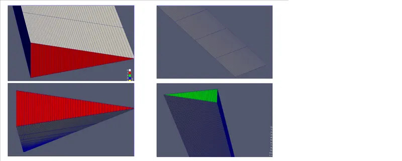
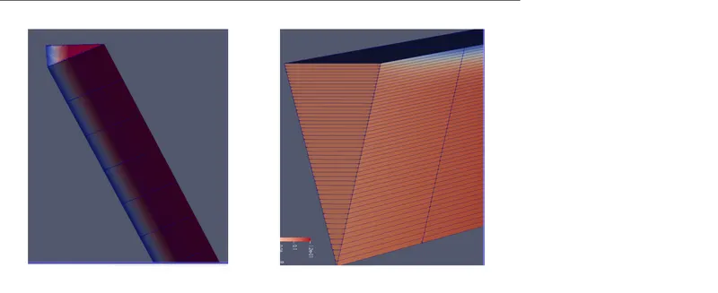
velocity :
pressure: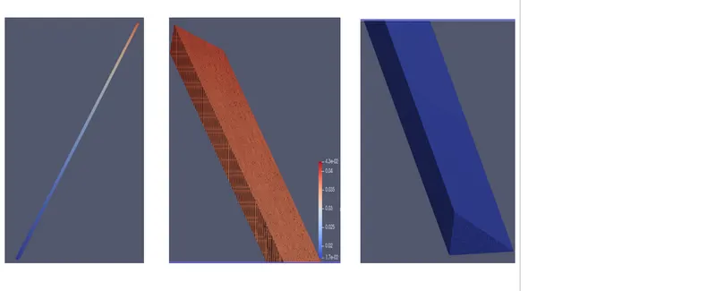
Graphs
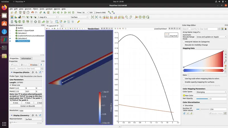
velocity and pressure:
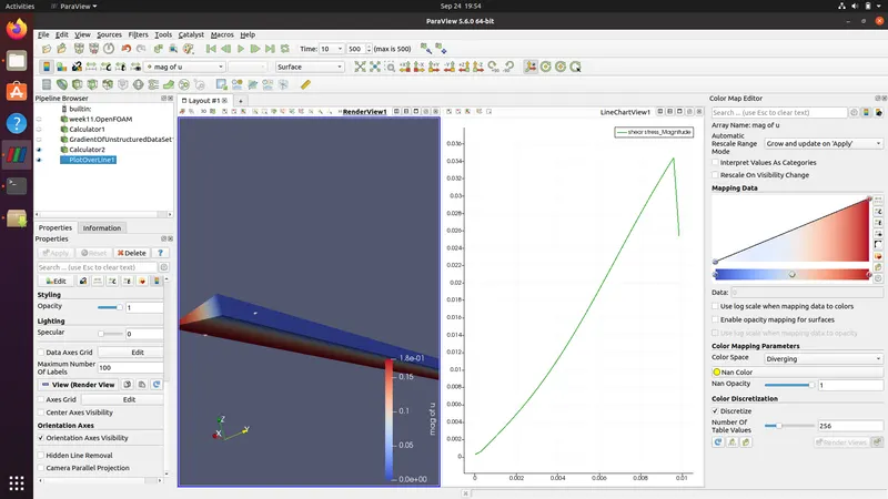
Shear stress
Conclusion:
- we plot the graph after the fully developed flow in pipe
- Here, we can see that the no slip condition is largely to blame for the velocity at the walls turning out to be zero. The boundary layers form and tend to slow down as the flow moves more slowly. Because of this, the center's velocity rises. This is because the velocity profile of the equation and the pressure difference obtained from the equation match each other.
- Shear stresses develop when a fluid moves because of how the flow's constituent particles move concerning one another. The fluid velocity in a pipe remains zero at the pipe wall. Because the adjacent fluid layers move at varying speeds, the shear force is produced.
- The shear stress is linearly related to the velocity gradient if the value of is `mu`constant. More shear stress in the walls as the velocity change is greater.