Simulation of Flow through a pipe
Aim:
- Generation of blockMeshDict using the wedge boundary condition. Create the blockMeshDict file in MATLAB such that the mesh is automatically created for various wedge angle.
- Simulating the pipe flow in OpenFOAM using icoFoam solver.
- Post-process the velocity profile and shear stress and compare the simulation results with analytical results obtained using the Hagen-Poiseuille equation.
Theory:
The pipe flow is a branch of hydraulics and fluid mechanics, wherein the liquid flow takes place within a closed conduit. Since pipe flow is confined within a closed conduit, it does not exert direct atmospheric pressure but exerts hydraulic pressure on the conduit. Hagen–Poiseuille law is a physical law that gives the pressure drop in an incompressible and Newtonian fluid in laminar flow flowing through a long cylindrical pipe of a constant cross-section.
Hydrodynamic Entrance Length:
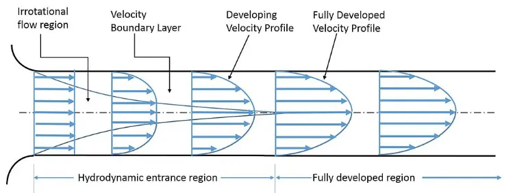
Hydrodynamic entrance length is the distance a flow travels in a pipe before it becomes fully developed. Entrance length refers to the length of the entry region, the area following the pipe entrance where effects originating from the interior wall of the pipe propagate into the flow as an expanding boundary layer. When the boundary layer expands to fill the entire pipe, the developing flow becomes a fully developed flow, where flow characteristics no longer change with increased distance along the pipe.
Analytical results obtained for given initial and boundary conditions:
The fluid flowing through the pipe is water
- Density = `rho=1000(Kg)/m^3`
- Dynamic viscosity = `mu=8.9*10^-4 Pa*s`
- Kinematic viscosity =`nu=1e-06 m^2/s`
- Reynolds number= Re= 2100
- The diameter of pipe= D= 0.01m
- Length of the pipe, L= 0.05*ReD= 0.05*2100*0.01= 1.05m, but to visualize the fully developed region, the length of the pipe is taken as L= 1.2m
- Inlet flow velocity = `V_(avg)=(Re*mu)/(rho*D)=(2100*8.9*10^-4)/(1000*0.01)=0.1869m/s`
- Maximum velocity = `V_(max)=2*V_(avg)=2*0.1869=0.3738`
- Pressure drop = `DeltaP=(32*mu*L*V_(avg))/D^2=(32*8.9*10^-4*1.2*0.1869)/0.01^2=63.8949Pa`
- Kinematic pressure drop = `DeltaP_k=(DeltaP)/rho=63.8749/1000=0.0638749m^2/s^`
Octave code to generate blockMeshDict file:
clc
clear all
close all

%% Variable values
diameter = 0.01;
r = diameter/2;
L = 1.2;
theta = 4;

%% Specifying string for header part
h1 = '/*––––––––––––––––––––––––––––––--*- C++ -*–––––––––––––––––––––––––––––––––-* ';
h2 = '| =========                 |                                                 | ';
h3 = '| \      /  F ield         | OpenFOAM: The Open Source CFD Toolbox           | ';
h4 = '|  \    /   O peration     | Version:  4.0                                   | ';
h5 = '|   \  /    A nd           | Web:      www.OpenFOAM.org                      | ';
h6 = '|    \/     M anipulation  |                                                 | ';
h7 = ' *–––––––––––––––––––––––––––––––––––––––––––––––––––––––––––––––––––––––––––*/ ';
h8 = ' FoamFile';
h9 = '{';
h10 = '     version     2.0;';
h11 = '     format      ascii;';
h12 = '     class       dictionary;';
h13 = '     object      blockMeshDict;';
h14 = '}';
h15 = '// * * * * * * * * * * * * * * * * * * * * * * * * * * * * * * * * * * * * * //';

conv = 'convertToMeters 1;';

s1 = blanks(5);
s2 = blanks(10);
s3 = blanks(15);

v0 = [0 0 0];
v1 = [r*sind(theta/2) r*cosd(theta/2) 0];
v2 = [-r*sind(theta/2) r*cosd(theta/2) 0];
v3 = [0 0 L];
v4 = [r*sind(theta/2) r*cosd(theta/2) L];
v5 = [-r*sind(theta/2) r*cosd(theta/2) L];

block = 'hex (0 0 1 2 3 3 4 5) (1 20 200) simpleGrading (1 0.5 1)';
edge1 = 'arc 1 2';
edge2 = 'arc 4 5';

e1 = [0 r 0];
e2 = [0 r L];

inlet = '(0 0 2 1)';
outlet = '(3 4 5 3)';
wedge1 = '(0 1 4 3)';
wedge2 = '(3 5 2 0)';
wall = '(4 1 2 5)';
axis = '(0 3 3 0)';

final = '// ************************************************************************* //';

%% Writing the blockMeshDict
f1 = fopen('blockMeshDict.txt','w');

fprintf(f1,'%s n',h1);
fprintf(f1,'%s n',h2);
fprintf(f1,'%s n',h3);
fprintf(f1,'%s n',h4);
fprintf(f1,'%s n',h5);
fprintf(f1,'%s n',h6);
fprintf(f1,'%s n',h7);
fprintf(f1,'%s n',h8);
fprintf(f1,'%s n',h9);
fprintf(f1,'%s n',h10);
fprintf(f1,'%s n',h11);
fprintf(f1,'%s n',h12);
fprintf(f1,'%s n',h13);
fprintf(f1,'%s n',h14);
fprintf(f1,'%s n',h15);
fprintf(f1,'n');

fprintf(f1,'%s n',conv);
fprintf(f1,'n');

fprintf(f1,'%s n','vertices');
fprintf(f1,'%s n','(');
fprintf(f1,'%s (%f %f %f) n',s1,v0(1),v0(2),v0(3));
fprintf(f1,'%s (%f %f %f) n',s1,v1(1),v1(2),v1(3));
fprintf(f1,'%s (%f %f %f) n',s1,v2(1),v2(2),v2(3));
fprintf(f1,'%s (%f %f %f) n',s1,v3(1),v3(2),v3(3));
fprintf(f1,'%s (%f %f %f) n',s1,v4(1),v4(2),v4(3));
fprintf(f1,'%s (%f %f %f) n',s1,v5(1),v5(2),v5(3));
fprintf(f1,'%s n',');');
fprintf(f1,'n');

fprintf(f1,'%s n','blocks');
fprintf(f1,'%s n','(');
fprintf(f1,'%s %s n',s1,block);
fprintf(f1,'%s n',');');
fprintf(f1,'n');

fprintf(f1,'%s n','edges');
fprintf(f1,'%s n','(');
fprintf(f1,'%s %s (%f %f %f) n',s1,edge1,e1(1),e1(2),e1(3));
fprintf(f1,'%s %s (%f %f %f) n',s1,edge2,e2(1),e2(2),e2(3));
fprintf(f1,'%s n',');');
fprintf(f1,'n');

fprintf(f1,'%s n','boundary');
fprintf(f1,'%s n','(');

fprintf(f1,'%s %s n',s1,'inflow');
fprintf(f1,'%s %s n',s1,'{');
fprintf(f1,'%s %s n',s2,'type patch;');
fprintf(f1,'%s %s n',s2,'faces');
fprintf(f1,'%s %s n',s2,'(');
fprintf(f1,'%s %s n',s3,inlet);
fprintf(f1,'%s %s n',s2,');');
fprintf(f1,'%s %s n',s1,'}');

fprintf(f1,'%s %s n',s1,'outflow');
fprintf(f1,'%s %s n',s1,'{');
fprintf(f1,'%s %s n',s2,'type patch;');
fprintf(f1,'%s %s n',s2,'faces');
fprintf(f1,'%s %s n',s2,'(');
fprintf(f1,'%s %s n',s3,outlet);
fprintf(f1,'%s %s n',s2,');');
fprintf(f1,'%s %s n',s1,'}');

fprintf(f1,'%s %s n',s1,'front');
fprintf(f1,'%s %s n',s1,'{');
fprintf(f1,'%s %s n',s2,'type wedge;');
fprintf(f1,'%s %s n',s2,'faces');
fprintf(f1,'%s %s n',s2,'(');
fprintf(f1,'%s %s n',s3,wedge1);
fprintf(f1,'%s %s n',s2,');');
fprintf(f1,'%s %s n',s1,'}');

fprintf(f1,'%s %s n',s1,'back');
fprintf(f1,'%s %s n',s1,'{');
fprintf(f1,'%s %s n',s2,'type wedge;');
fprintf(f1,'%s %s n',s2,'faces');
fprintf(f1,'%s %s n',s2,'(');
fprintf(f1,'%s %s n',s3,wedge2);
fprintf(f1,'%s %s n',s2,');');
fprintf(f1,'%s %s n',s1,'}');

fprintf(f1,'%s %s n',s1,'wall');
fprintf(f1,'%s %s n',s1,'{');
fprintf(f1,'%s %s n',s2,'type wall;');
fprintf(f1,'%s %s n',s2,'faces');
fprintf(f1,'%s %s n',s2,'(');
fprintf(f1,'%s %s n',s3,wall);
fprintf(f1,'%s %s n',s2,');');
fprintf(f1,'%s %s n',s1,'}');

fprintf(f1,'%s %s n',s1,'axis');
fprintf(f1,'%s %s n',s1,'{');
fprintf(f1,'%s %s n',s2,'type empty;');
fprintf(f1,'%s %s n',s2,'faces');
fprintf(f1,'%s %s n',s2,'(');
fprintf(f1,'%s %s n',s3,axis);
fprintf(f1,'%s %s n',s2,');');
fprintf(f1,'%s %s n',s1,'}');

fprintf(f1,'%s n',');');
fprintf(f1,'n');

fprintf(f1,'%s n','mergePatchPairs');
fprintf(f1,'%s n','(');
fprintf(f1,'%s n',');');
fprintf(f1,'n');
fprintf(f1,'%s n',final);

fclose(f1);
An octave code was written to generate the BlockMeshDict file. By doing so, a lot of time is saved if there is a requirement to perform simulations at different wedge angles. For this flow simulation, water is taken as the working fluid and a wedge angle of 4 degrees is taken. Likewise, if we want to create a file for any other wedge angle, the wedge angle value(theta) is changed in the code and the required BlockMeshDict file is generated.
blockMeskDict file generated:
/*––––––––––––––––––––––––––––––--*- C++ -*–––––––––––––––––––––––––––––––––-*
| =========                 |                                                 |
| \      /  F ield         | OpenFOAM: The Open Source CFD Toolbox           |
|  \    /   O peration     | Version:  4.0                                   |
|   \  /    A nd           | Web:      www.OpenFOAM.org                      |
|    \/     M anipulation  |                                                 |
 *–––––––––––––––––––––––––––––––––––––––––––––––––––––––––––––––––––––––––––*/
 FoamFile
{
     version     2.0;
     format      ascii;
     class       dictionary;
     object      blockMeshDict;
}
// * * * * * * * * * * * * * * * * * * * * * * * * * * * * * * * * * * * * * //

convertToMeters 1;

vertices
(
      (0.000000 0.000000 0.000000)
      (0.000174 0.004997 0.000000)
      (-0.000174 0.004997 0.000000)
      (0.000000 0.000000 1.200000)
      (0.000174 0.004997 1.200000)
      (-0.000174 0.004997 1.200000)
);

blocks
(
      hex (0 0 1 2 3 3 4 5) (1 20 200) simpleGrading (1 0.5 1)
);

edges
(
      arc 1 2 (0.000000 0.005000 0.000000)
      arc 4 5 (0.000000 0.005000 1.200000)
);

boundary
(
      inflow
      {
           type patch;
           faces
           (
                (0 0 2 1)
           );
      }
      outflow
      {
           type patch;
           faces
           (
                (3 4 5 3)
           );
      }
      front
      {
           type wedge;
           faces
           (
                (0 1 4 3)
           );
      }
      back
      {
           type wedge;
           faces
           (
                (3 5 2 0)
           );
      }
      topwall
      {
           type wall;
           faces
           (
                (4 1 2 5)
           );
      }
      axis
      {
           type empty;
           faces
           (
                (0 3 3 0)
           );
      }
);

mergePatchPairs
(
);

// ************************************************************************* //
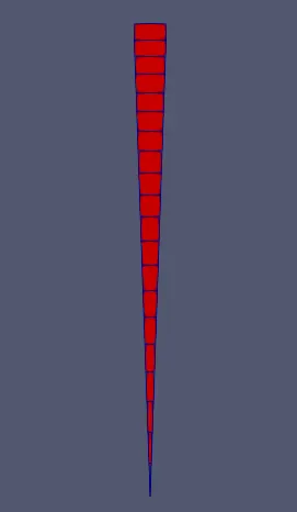
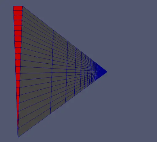
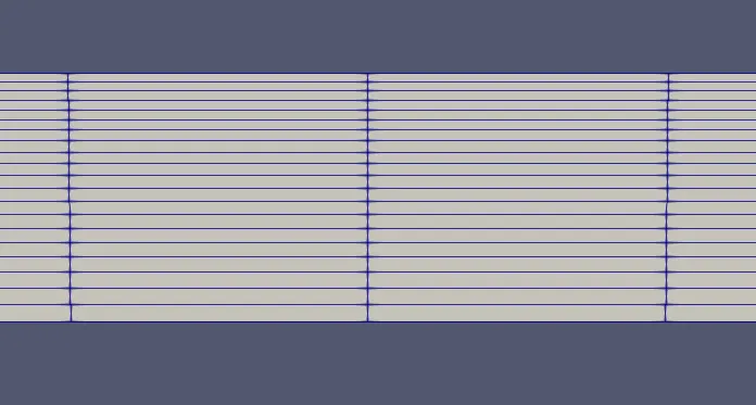
The blockMeshDict file contains the geometry for the required simulations, wherein, various boundary conditions, mesh, and mesh grading for the blocks are defined. In this problem, only one block is defined, with 1, 20, and 200 mesh elements defined in x, y, and z-direction respectively. Only one mesh element is defined in the x-direction because we are not interested in the change of flow properties in this direction. Also, a mesh grading factor of 0.5 is given in the y-direction to generate a finer mesh near the boundary of the pipe so as to capture the boundary layer formation.
Pressure code:
/*--------------------------------*- C++ -*----------------------------------*
  =========                 |
  \      /  F ield         | OpenFOAM: The Open Source CFD Toolbox
   \    /   O peration     | Website:  https://openfoam.org
    \  /    A nd           | Version:  7
     \/     M anipulation  |
*---------------------------------------------------------------------------*/
FoamFile
{
    version     2.0;
    format      ascii;
    class       volScalarField;
    object      p;
}
// * * * * * * * * * * * * * * * * * * * * * * * * * * * * * * * * * * * * * //

dimensions      [0 2 -2 0 0 0 0];

internalField   uniform 0;

boundaryField
{
    outflow
    {
    	type		  fixedValue;
    	value		  uniform 0.063874;
    }
    inflow
    {
    	type		  zeroGradient;
    }
    topwall
    {
    	type		  zeroGradient;
    }
    front
    {
    	type		  wedge;
    }
    back
    {
    	type		  wedge;
    }
    axis
    {
    	type		  empty;
    }
}

// ************************************************************************* //
The pressure code is used to define pressure boundary conditions for the geometry. In this problem, velocity-inlet, pressure-outlet boundary condition is used. The pressure-outlet boundary condition is defined here.
Velocity code:
/*--------------------------------*- C++ -*----------------------------------*
  =========                 |
  \      /  F ield         | OpenFOAM: The Open Source CFD Toolbox
   \    /   O peration     | Website:  https://openfoam.org
    \  /    A nd           | Version:  7
     \/     M anipulation  |
*---------------------------------------------------------------------------*/
FoamFile
{
    version     2.0;
    format      ascii;
    class       volVectorField;
    object      U;
}
// * * * * * * * * * * * * * * * * * * * * * * * * * * * * * * * * * * * * * //

dimensions      [0 1 -1 0 0 0 0];

internalField   uniform (0 0 0);

boundaryField
{
    outflow
    {
    	type		  zeroGradient;
    }
    inflow
    {
    	type		  fixedValue;
    	value		  uniform (0 0 0.1869);
    }

    topwall
    {
    	type		  zeroGradient;
    }
    front
    {
    	type		  wedge;
    }
    back
    {
    	type		  wedge;
    }
    axis
    {
    	type		  empty;
    }
}

//************************************************************************* //
The velocity code is used to define the velocity boundary conditions of the geometry. In this problem, velocity-inlet, pressure-outlet boundary condition is used. The velocity-inlet boundary condition is defined here.
Transport properties code:
/*--------------------------------*- C++ -*----------------------------------*
  =========                 |
  \      /  F ield         | OpenFOAM: The Open Source CFD Toolbox
   \    /   O peration     | Website:  https://openfoam.org
    \  /    A nd           | Version:  7
     \/     M anipulation  |
*---------------------------------------------------------------------------*/
FoamFile
{
    version     2.0;
    format      ascii;
    class       dictionary;
    location    "constant";
    object      transportProperties;
}
// * * * * * * * * * * * * * * * * * * * * * * * * * * * * * * * * * * * * * //

nu              [0 2 -1 0 0 0 0] 1e-6;


// ************************************************************************* //
Here, the kinematic viscosity of the working fluid is defined. For water, kinematic viscocity= 1e-06 m^2/s.
OpenFOAM outputs:
The geometry is generated in the OpenFOAM platform, for a wedge angle of 4 degrees.
Outputs:
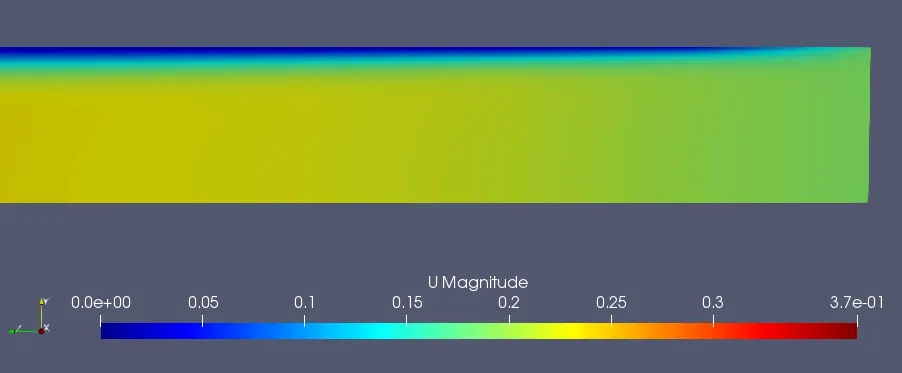
The following is the velocity contours obtained near the inlet of the pipe. The velocity magnitude is relatively low, and we can visualize the beginning of the formation of the boundary layer separation near the wall of the pipe.
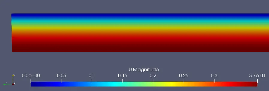
The following is the velocity contours obtained near the outlet of the pipe. We can see that the velocity magnitude has reached its peak value near the center of the pipe, ie, almost 0.37m/s. This is twice the average velocity of water flowing in the pipe.
Velocity profiles:
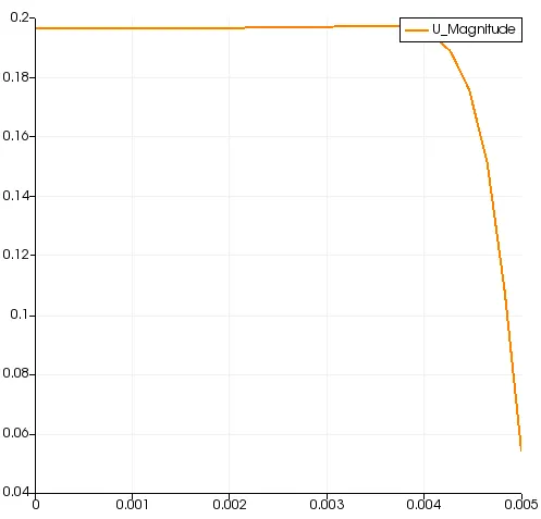
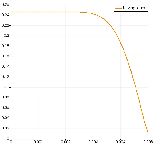
The following velocity profiles were obtained at a distance of
1. 0.005m from the pipe inlet
2. 0.05m from the pipe inlet
3. 0.1m from the pipe inlet
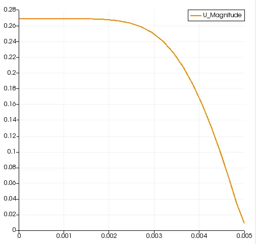
4. 0.25m from the pipe inlet
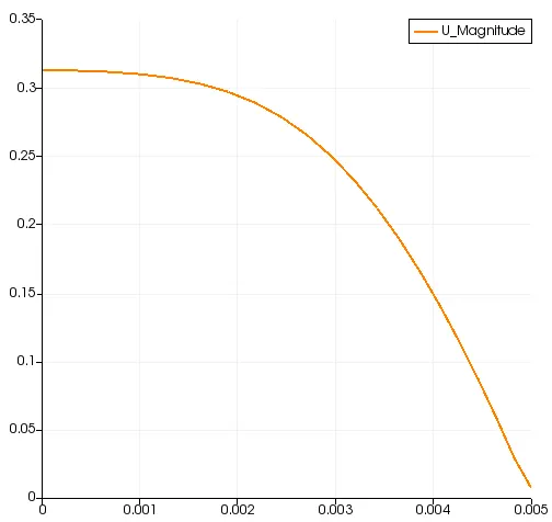
5. 0.5m from the pipe inlet
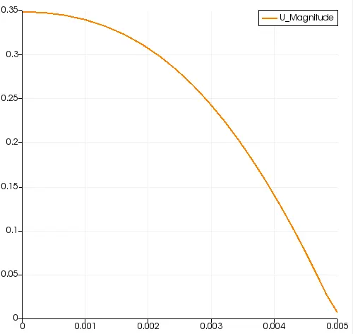
6. 0.75m from the pipe inlet
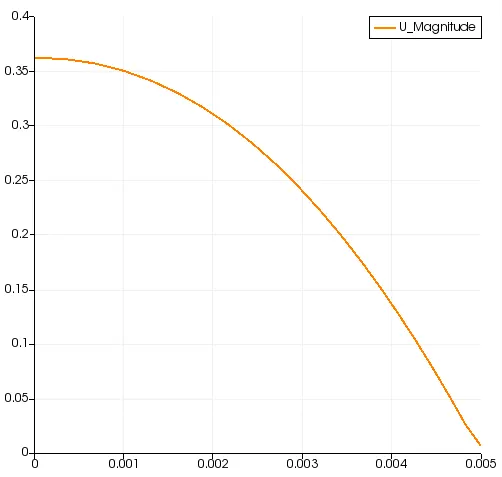
7. 1.0m from the pipe inlet
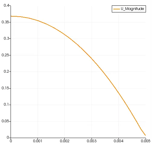
8. 1.15m from the pipe inlet
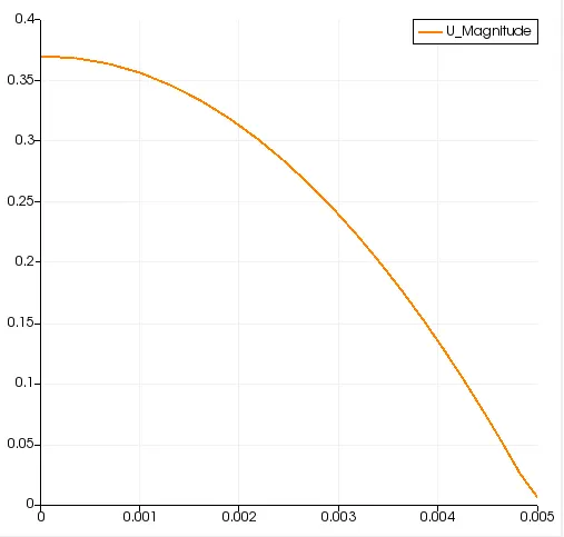
From the obtained velocity profiles, it is clear that the magnitude of velocity remains relatively low and constant throughout the pipe section at the initial stages of the flow. This varies as the fluid moves further, the velocity curve becomes parabolic in nature, mainly due to the formation of boundary layers near the wall. At the end of the hydraulic length, the maximum velocity of flow becomes twice that of the average velocity, and this trend will remain the same further.
Shear stress:
The shear stress is given by, `tau=mu*(du)/(dy)`
Where `mu`=Dynamic viscosity
`tau`=Shear stress
`(du)/(dy)`=Rate of shear deformation
Shear stress profile at 1.15m from the pipe inlet where the flow is completely developed is given below
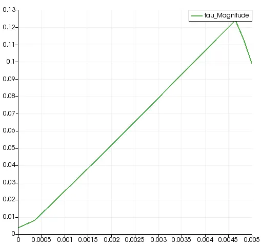
The above graph represents the change in the magnitude of shear stress radially at a distance of 1.15m from the inlet of the pipe. The shear stress is maximum near the walls and minimum near the center of the pipe.
Conclusions:
By performing the simulation of flow through a pipe, on OpenFOAM, the following conclusions can be drawn
- The velocity profile of flow through a pipe remains the same after it has crossed the hydraulic length. The hydraulic length for a laminar flow depends upon the hydraulic diameter of the pipe.
- Once the fluid has crossed the hydraulic length, the velocity of flow near the center of the pipe, ie, the maximum velocity will be twice that of the average velocity.
- The shear stress of the fluid after it crosses the hydraulic length will display a linear profile with the maximum shear stress acting near the wall of the pipe and the minimum acting near the center of the pipe.