Week 11 - Project - A pillar Design with Master Section
A PILLAR DEVELOPMENT WITH MASTER SECTION
Objective:
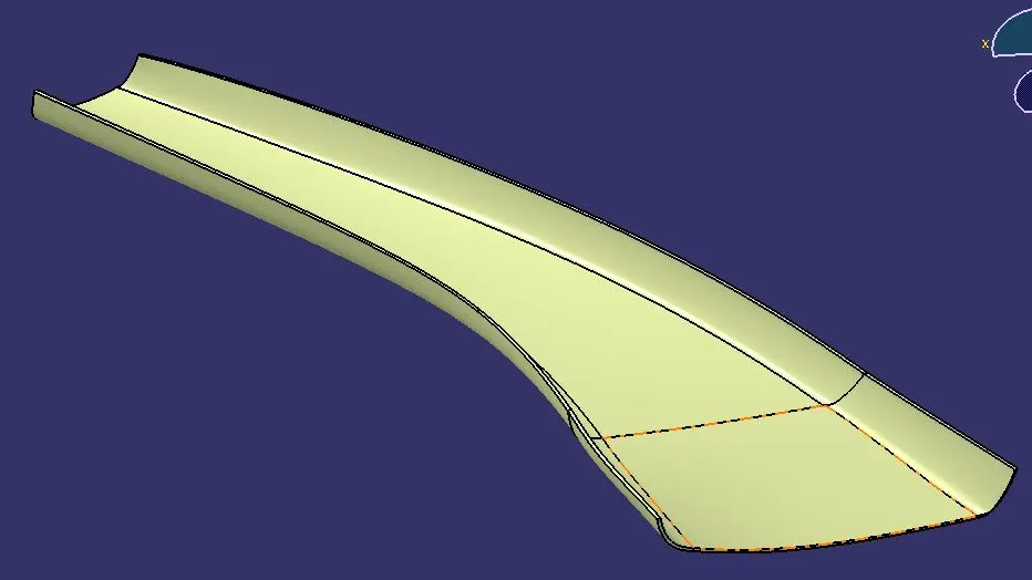
To develop the A pillar by following the given master section, creating tooling axis, dog house and perform Draft Analysis on the final plastic component.
Introduction:
In this project we are designing A pillar trim component using given class A surface by following master section. The approach includes creation of class B and class C surface by following the master section. After that we have to create a dog house and perform a draft analysis for the final component.
Master Section:
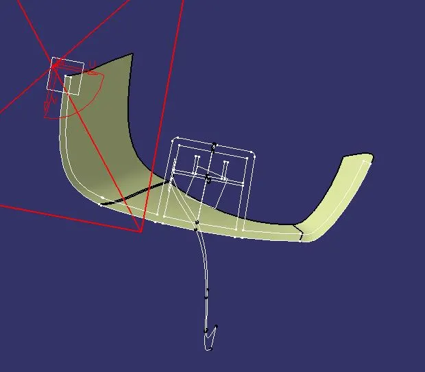
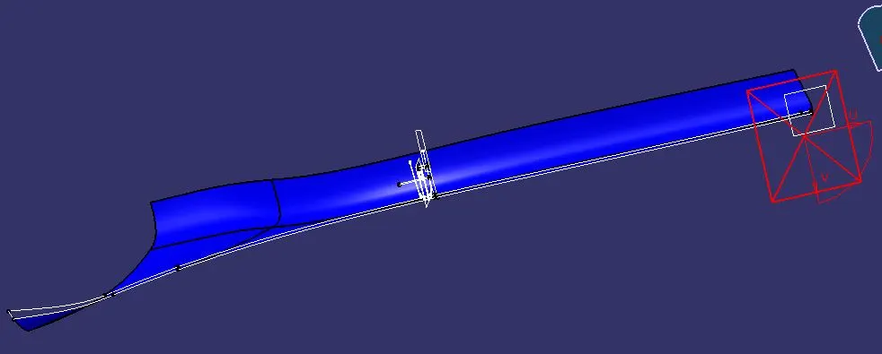
In automotive design,
a master section is a parameterized model of a vehicle body that guides the
design requirements for a component after technical styling. Master sections
are created during the concept validation and feasibility check stages. They help
the NPD team decide on the things like component thickness, B side feature
location and thickness, component feasibility, and component fixation strategy.
Class A Surface:
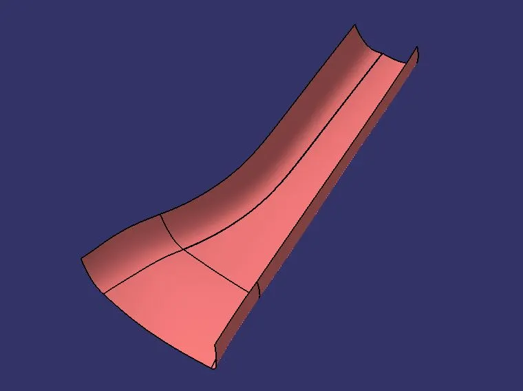
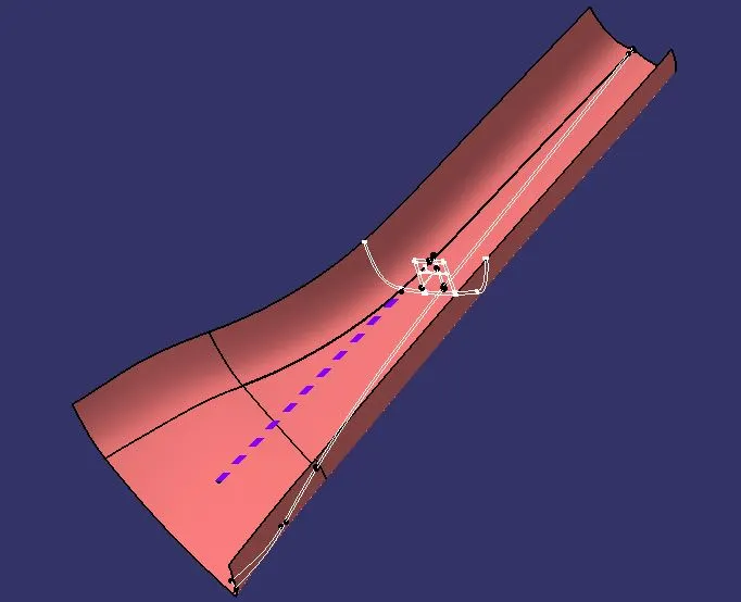
The given input surface is considered as Class A surface. Before creating a tooling axis, we have to check the connectivity of the surface and ensure there is no gap between the surfaces.
Tooling Axis:
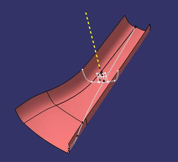
The direction in which the mold would open and close is called tooling axis. While creating the tooling axis give the tooling axis on a flat length surface or the surface which have a hole on it.
Create a point on the surface where we are going to create the dummy tooling axis and using line command create an axis. If there is a circle or flat length surface which is recommended. In this model we have to create a bisecting line by using two dummy tooling axis X and Y direction.
Side Core Tooling Axis:
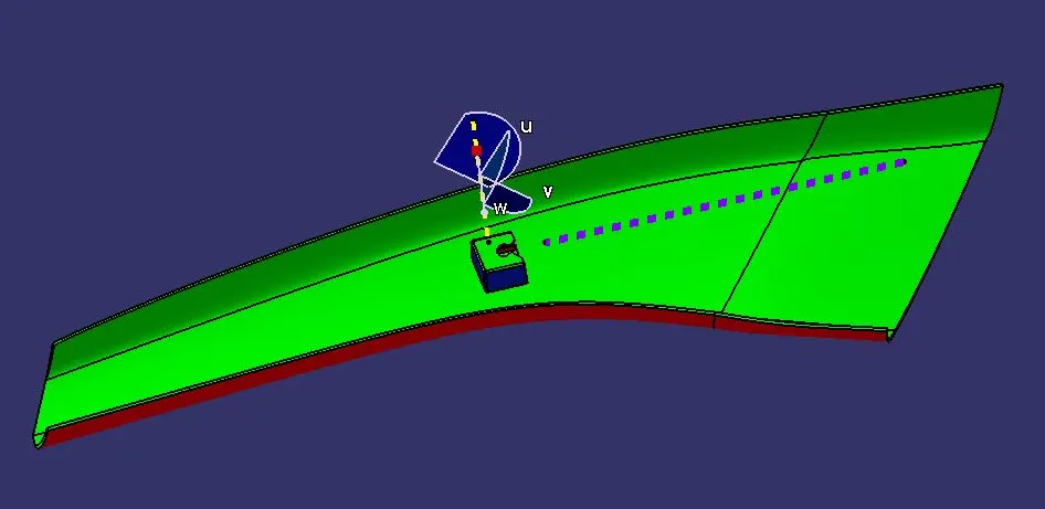
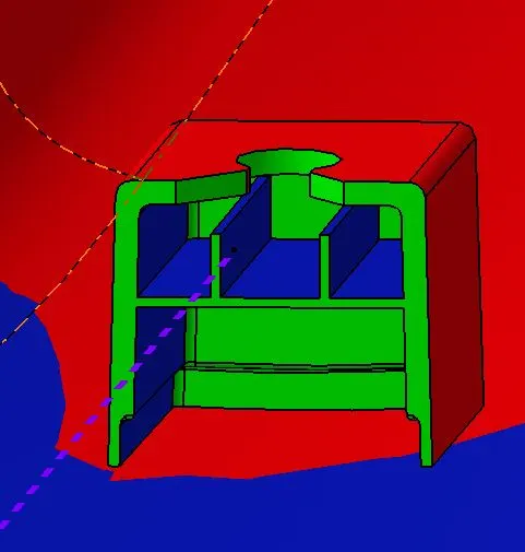
In this challenge we have create a side core tooling axis for dog house. The side tooling axis used to insert or eject the side core to the mold. Draft analysis is applied to dog houses to prevent component breakage during component ejection from the mold cavity.
Draft Analysis:
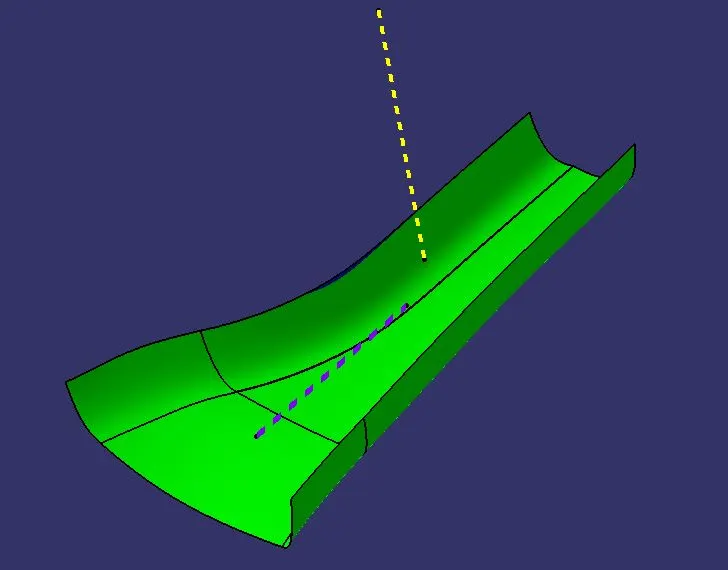
The draft analysis technique is used to analyze whether our part model created in CAD is manufacturable based on the draft condition applied. Here the part should get easily removed from the panel dies or mold. No parts can be ejected from the tool if it is having 90° profile from its base surface. A small draft angle is provided to each and every area of the component in order to get easy removal of the component from the tool. Here, we are providing a direction in which components from the tool. In other word it also lets us know whether the model is having a draft angle and how much is the draft angle from the tool direction.
Class B Surface:
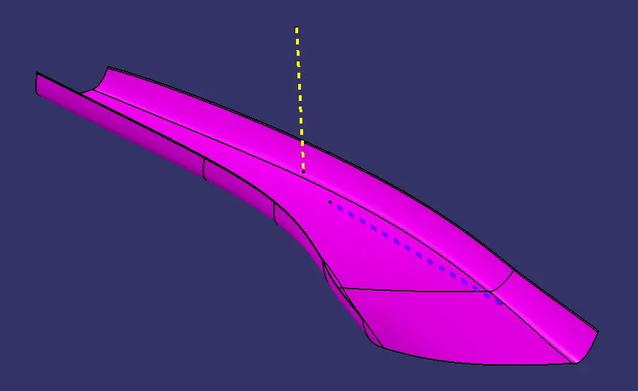
Class B surface is an offset surface to create a closed volume. To create a B surface, we have to offset the input surface with respect to the master section thickness. The offset surface is called Class B surface.
Class C surface:
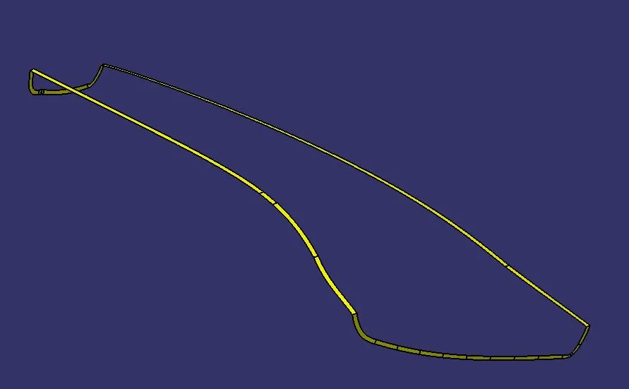
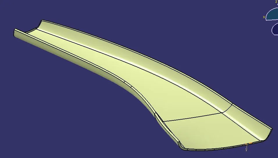
Class C surface is the surface which connect the class A and B surface together is known as Class C surface. It is created using sweep command. Boundary of the Class A surface is swept along the tooling direction by following the master section.
Class A and C Join:
Final Trim:
Dog House Creation:
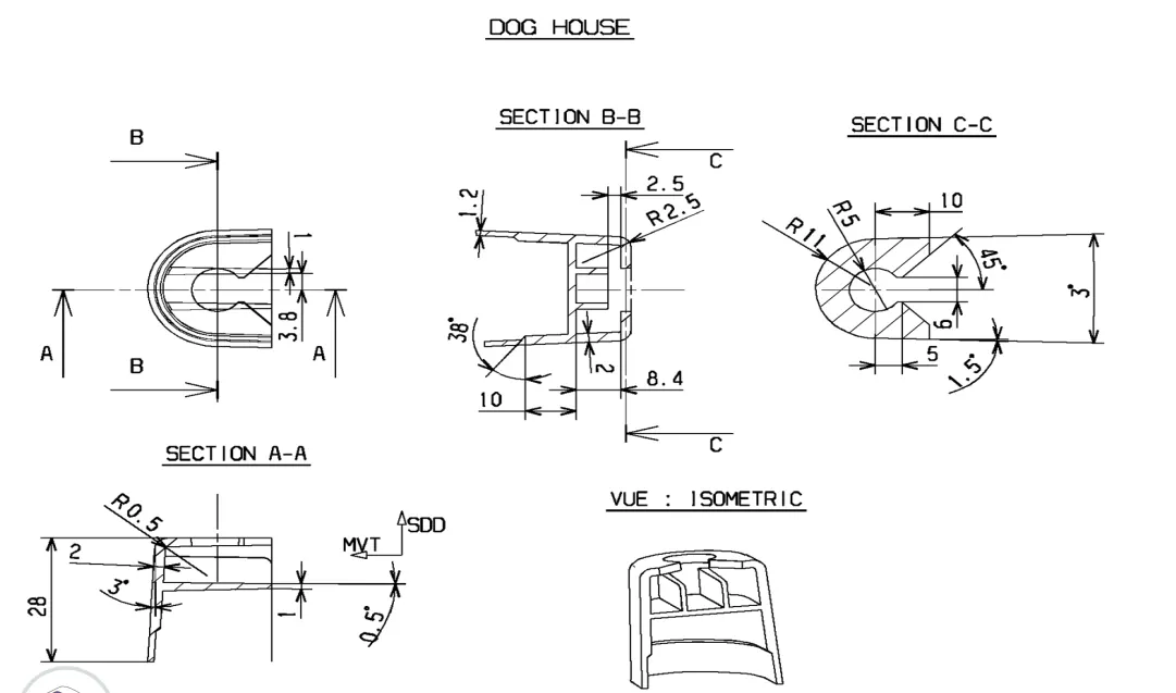
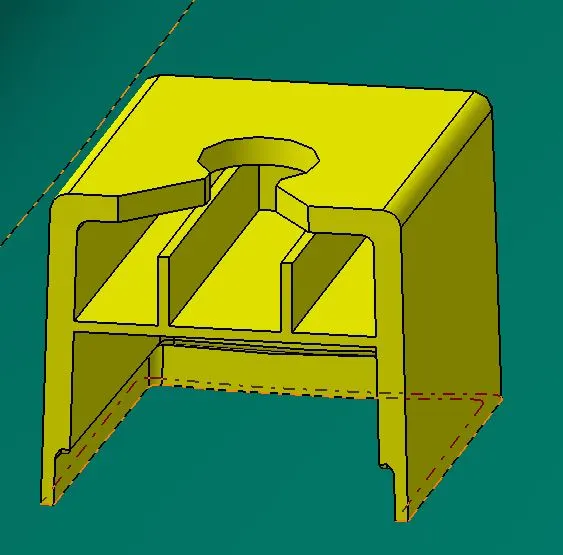
Doghouse is an engineering element used in the creation of plastic trim. Dog kennels are used as auxiliary elements. In order to increase their strength, snaps, locators, and other engineering features are occasionally mounted on them. Here the dog house dimensions are given the master section, we have create a dog house by following the master section.
Orientations:
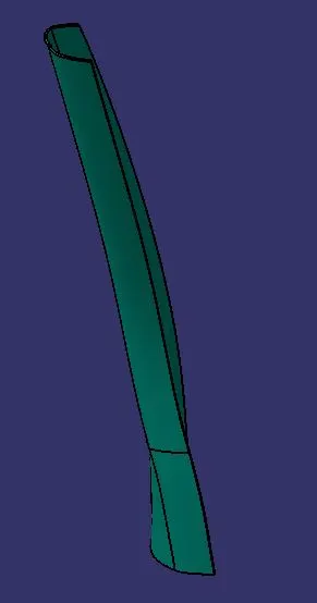
Front View:
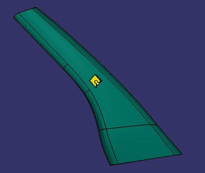
Right View:
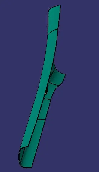
Top View:
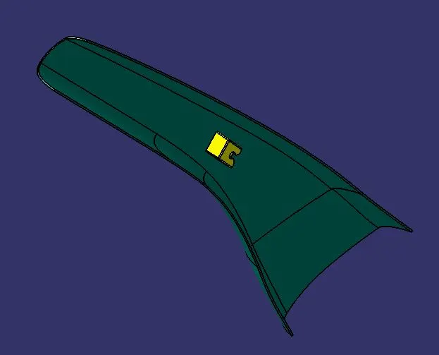
Isometric View:
Draft Analysis on Final Part:
Conclusion:
Thus, the A pillar and dog house was developed by following the given master section and draft analysis performed on the final plastic component.