Week 11 - Project - A pillar Design with Master Section
A PILLAR DESIGN WITH MASTER SECTION
AIM:
To create the A pillar design with master section and using through the given class-A surface. Also create the engineering features, us dog house.
OBJECTIVES:
- To create a tooling direction.
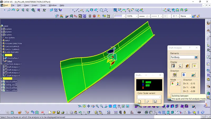
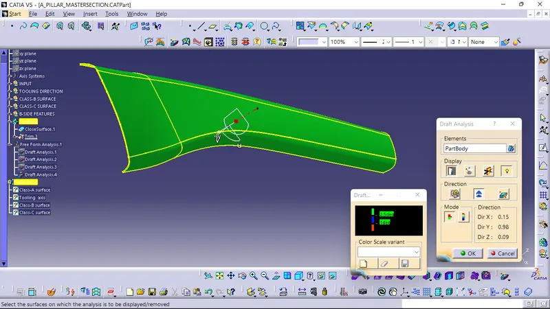
- To perform draft analysis for given class-A surface and prepare the final closed body.
- To design the A pillar plastic component by creating the B surface and C surface by using given class-A surface.
- Take the thickness of the component to be 2.5mm.
INTRODUCTION:
The input of the product designer is in the class-A surface and master section. The job of the plastic designer is to create the class-B and C surface keeping all the aspect of the mold.
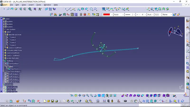
MASTER SECTION:
Reference for class-A,class-B & class-C surface.
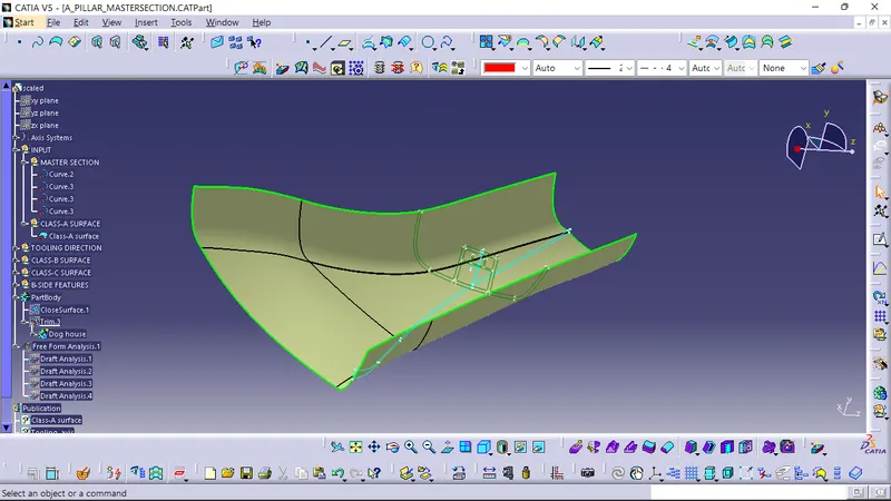
CLASS-A SURFACE:
- visibel surface and aesthetic look.
- Surface with textures.
- Surfaces provide by customer (OEM).
- Don't have any features like(ribs, snaps, boss etc) on class-A surface.
- Class-A surface is made from scanned data with different software like alias etc.
- Surfaces which are having CURVATURE CONTINUTY is called class-A.
Check the connectivity of the class-A surface ensure that there is no gap between the component, by using the join command. We can visually check it and by clicking boundary command, it has no open boundaries therefore first check completed.
TOOLING DIRECTION FOR PLASTIC PART:
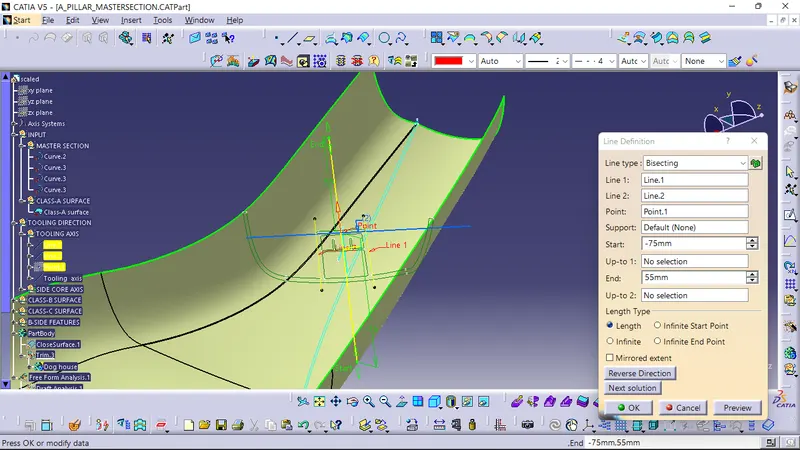
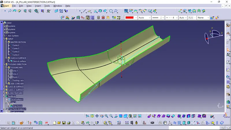
Tooling direction is main consideration for plastic part and mould parts because it defines the movement of mold part and possibility of plastic part to come out from the mold part.
- In moulding machine arrangement is given to open the mold along a direction which is know as tooling direction.
- The mold is built from two seperate halves (core and cavity) and tooling direction basically define the direction of mold pulls a part.
- Tooling direction is known as primary direction.
- But in A pillar design we have a master section based on that we considered the tooling direction.
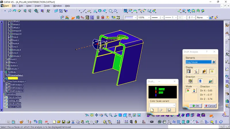
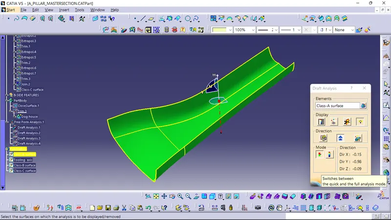
CLASS-A DRAFT ANALYSIS:
Class-B SURFACE:
- invisible surfaces.
- Surface mostly don't have textures.
- Surface need to be created according to the class-A surface.
- Having all features (ribs, snap, boss etc) in B side surface only.
- Surfaces which is having TANGENT CONTINUTY is called class-B.
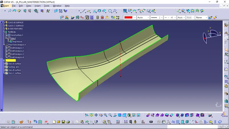
Is created with the help of A surface by using the offset, trim command, multi section surface command. First offset the class-A surface with 2.5mm as per thickness. In offset surface having on some patches are messing. For this patches we need to create the close surface by using commands (trim, sweep, multi section surface).
CLASS-C SURFACE:
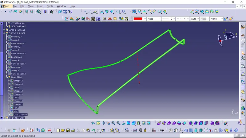
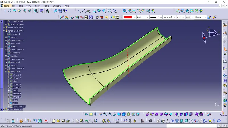
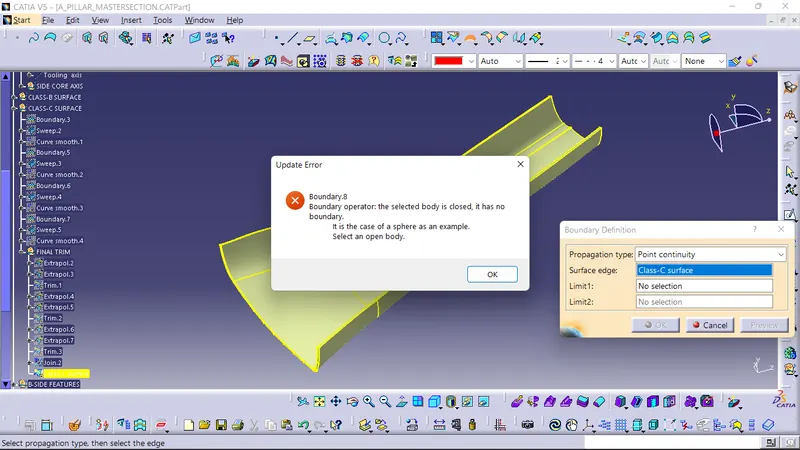
Class-C surface is created with the help of A surface by using the sweep and boundary command.
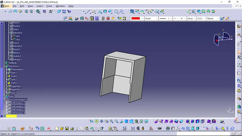
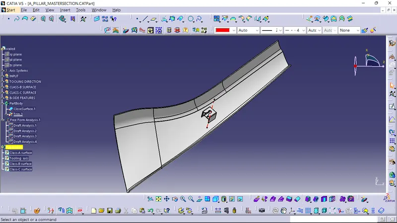
FINAL COMPONENT:
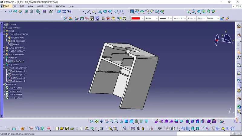
FINAL COMPONENT DRAFT ANALYSIS:
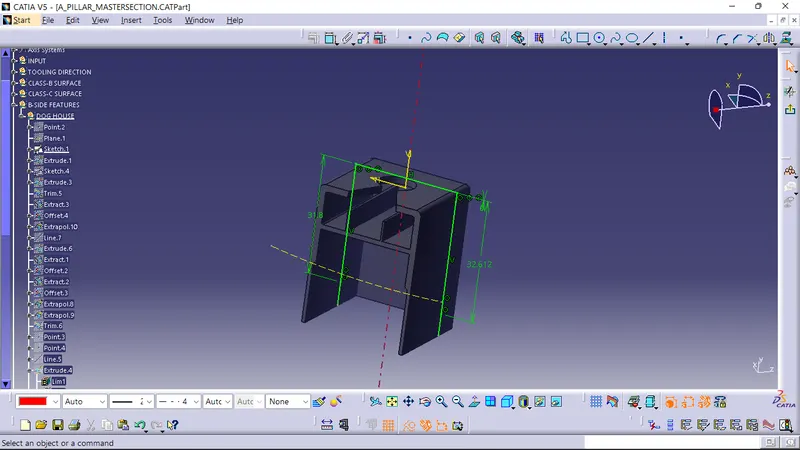
DOG HOUSE & RIBS: