Week 11 - Project - A pillar Design with Master Section
Week 11 - Project - A pillar Design with Master Section
Aim :
To create the A Pillar Design with the master section given as the intersection sketch with the Class A surface and create the tooling axis and perform the Draft analysis for the final solid part.
Objective :
- Create the required Tooling axis by using master section and bisecting methode.
- Design the Class-B and Class-C surfaces and close all three surfaces.
- Design the Dog house and its internal parts as given Drafts and mater section sketch.
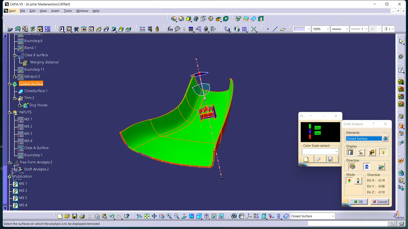
- Draft analysis for the final solid part and side core Draft analysis.
Theory :
Tooling Axis :
Class-A surface is first analyzed to create the tooling axis or tooling direction that molds pull apart in injection molding. Tooling direction is important for plastic product design as it decides direction for mold seperation.
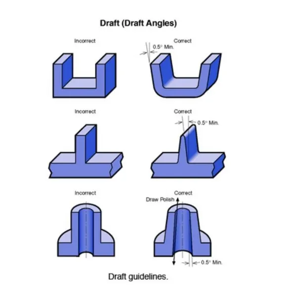
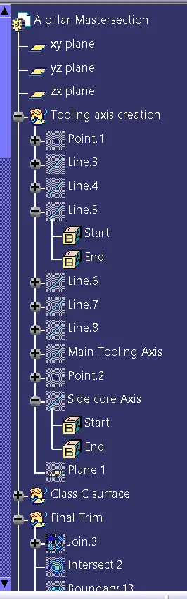
Step followed for creation of tooling axis :
- Reference point is first created on extracted surface.
- New axis system is deployed to plot clearance lines.
- The X-direction and Y-direction along the class-A were used to create tooling axis.
- Graphic properties of tooling axis were change before publishing.
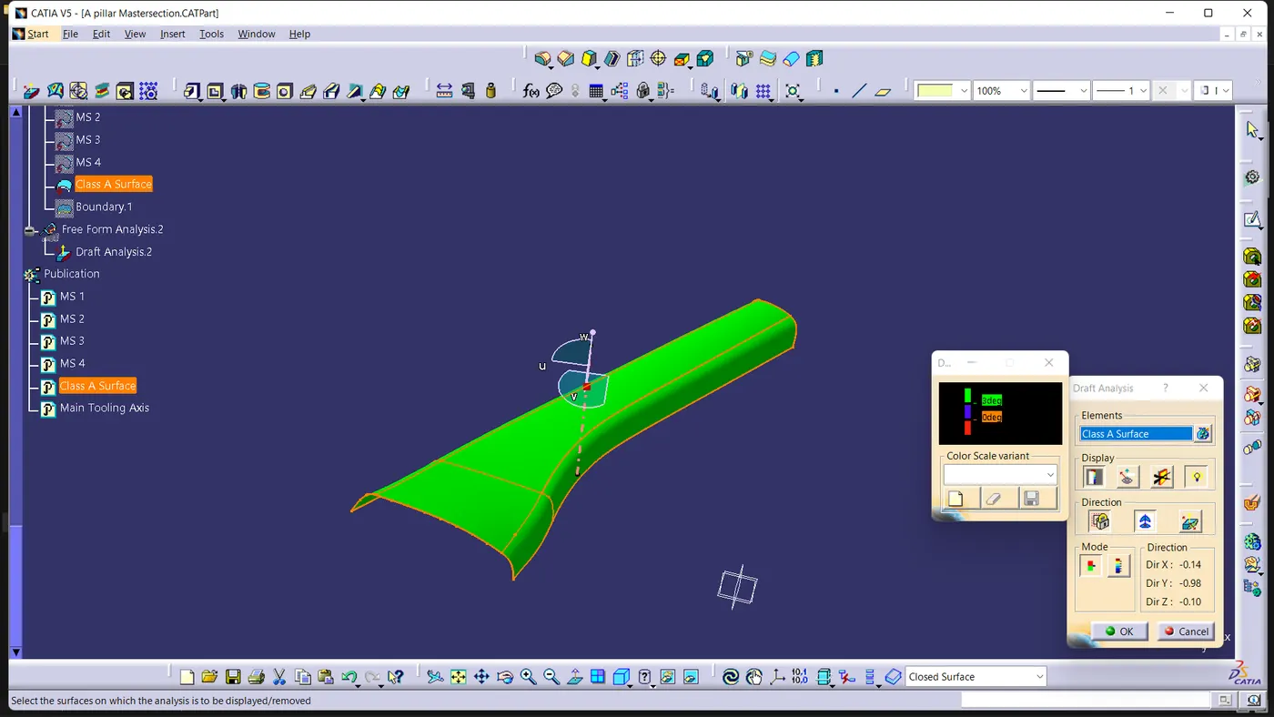
DRAFT ANALYSIS ON THE CLASS A SURFACE:
Next, We will perform a Draft Analysis on the Class A Surface itself:
Before starting with a Draft Analysis Operation, we will go to the 'Customize View Parameters' option under the 'View Toolbar'. Then we will enter the 'Customize View Mode' where we will go under the 'Mesh' option and select 'Material' and press 'OK'.
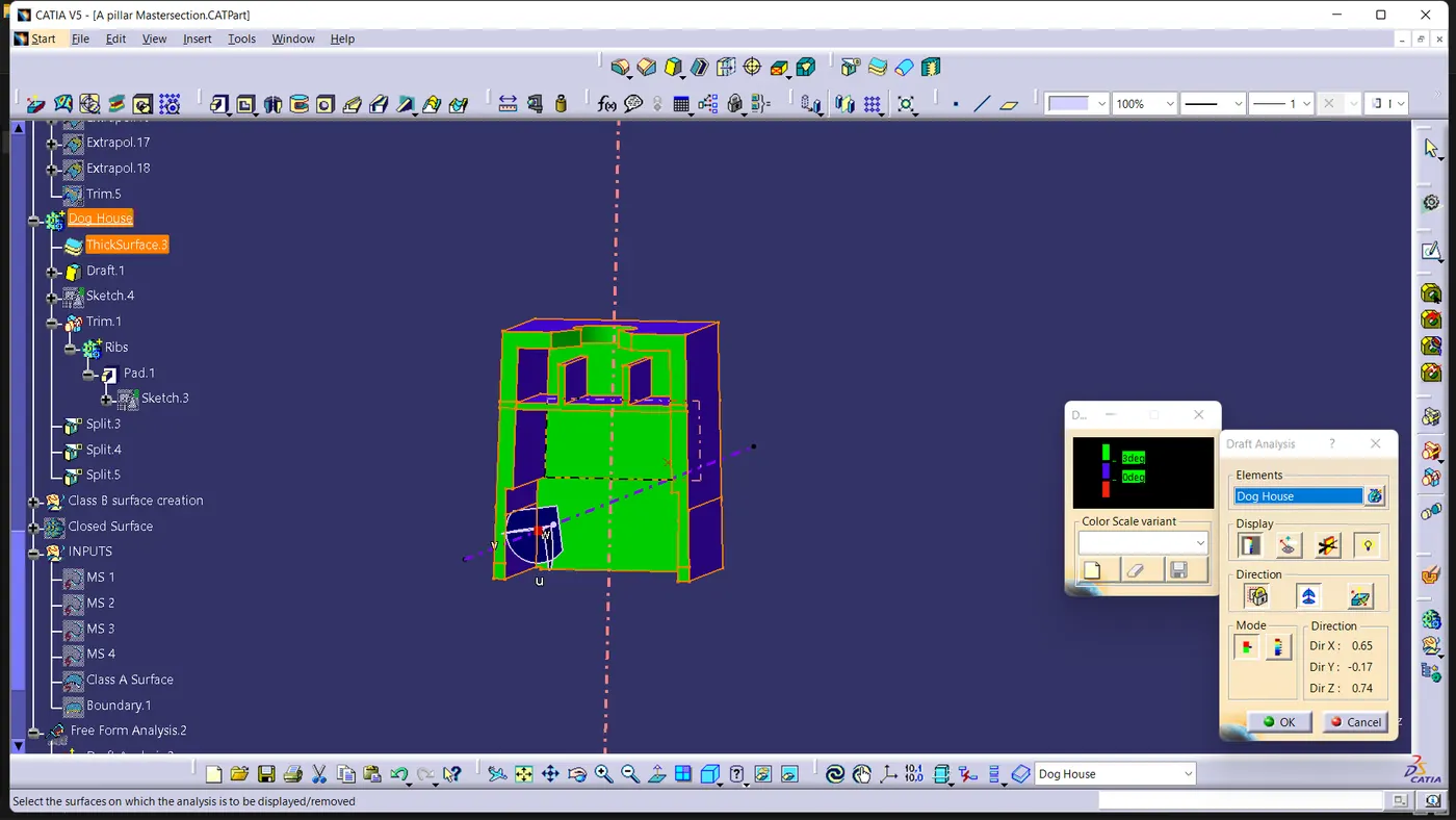
To start the Draft Analysis in the 'Generative Surface Design Workbench', we will go to 'Insert' and then look for the option called 'Analysis'. Once found, we will go under that and click on 'Feature Draft Analysis. This will open the 'Draft Analysis' Dialogue box. There, we will ensure that under 'Mode' we have selected 'Quick Analysis', under 'Display' we will select 'Show or Hide the Color Scale' and then select '3 Degrees' as the permissible draft angle. Then, under 'Direction' we will choose the icon with the symbol of the compass on it which stands for 'Use the Compass to define the new current draft direction'.
CLASS B SURFACE:
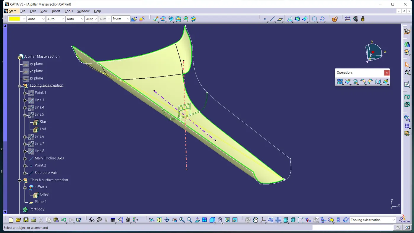
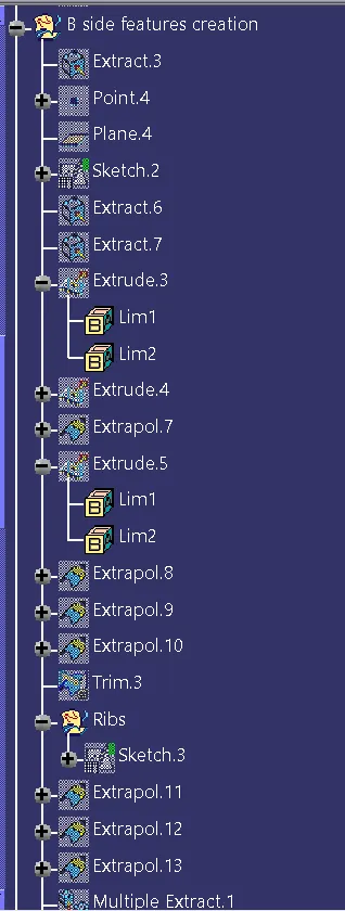
The thickness of the component as 2.5mm. Now we need to create a B surface which will be similar to the A surface at an offset value of 2.5mm. there are some discontinuities happened while offsetting the CLASS A surface so I repaired it to form a closed boundary by using the multiple extract, extrapolate, trim and fill surface commands and tools.
 CLASS C SURFACE:
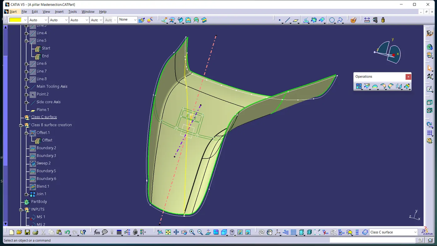
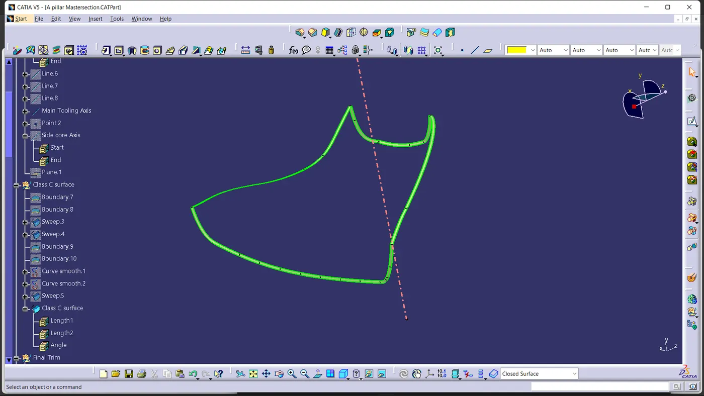
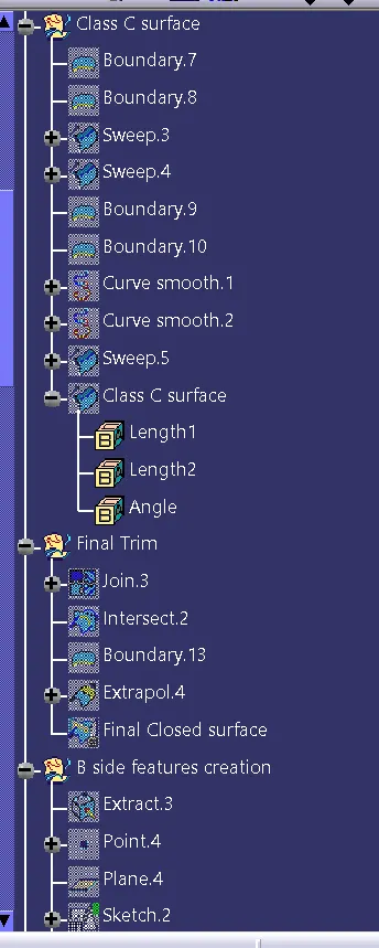
C surface is created with help of A-Surface by using the Sweep(with reference surface) and Boundary command separately, finally joined together to get the final C surface.
Final trim to obtain A - Pillar Plastic component:
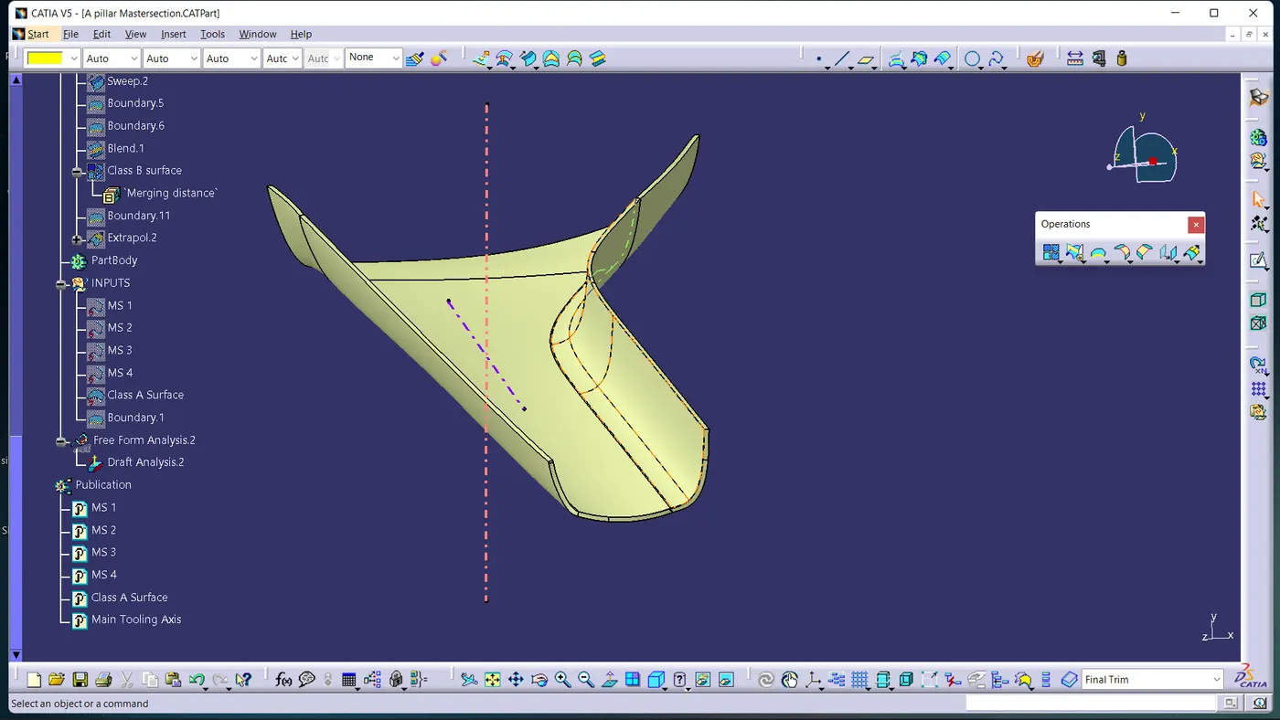
- The last step is triming the Class c surface with the Class B surface. Then the obtained surface is joined with Class A surface.
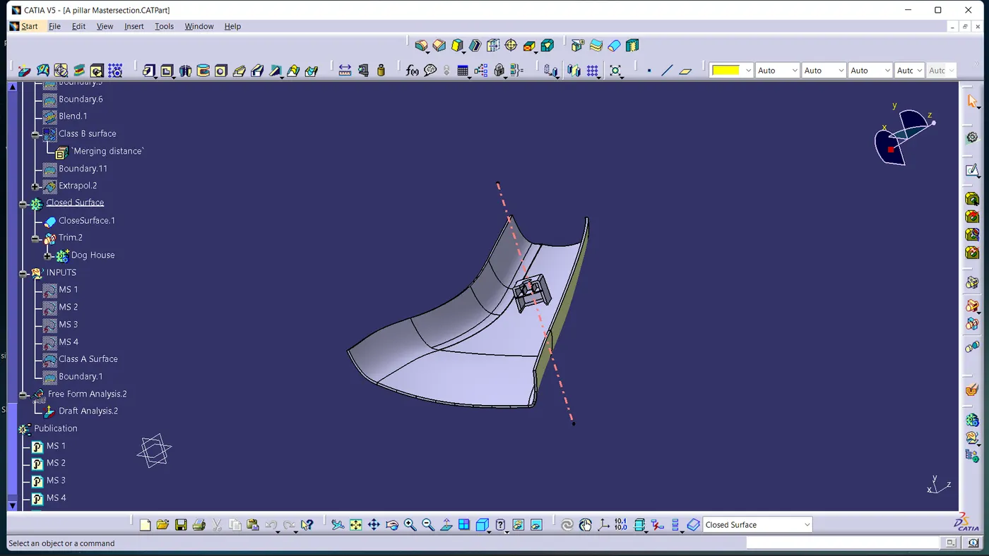
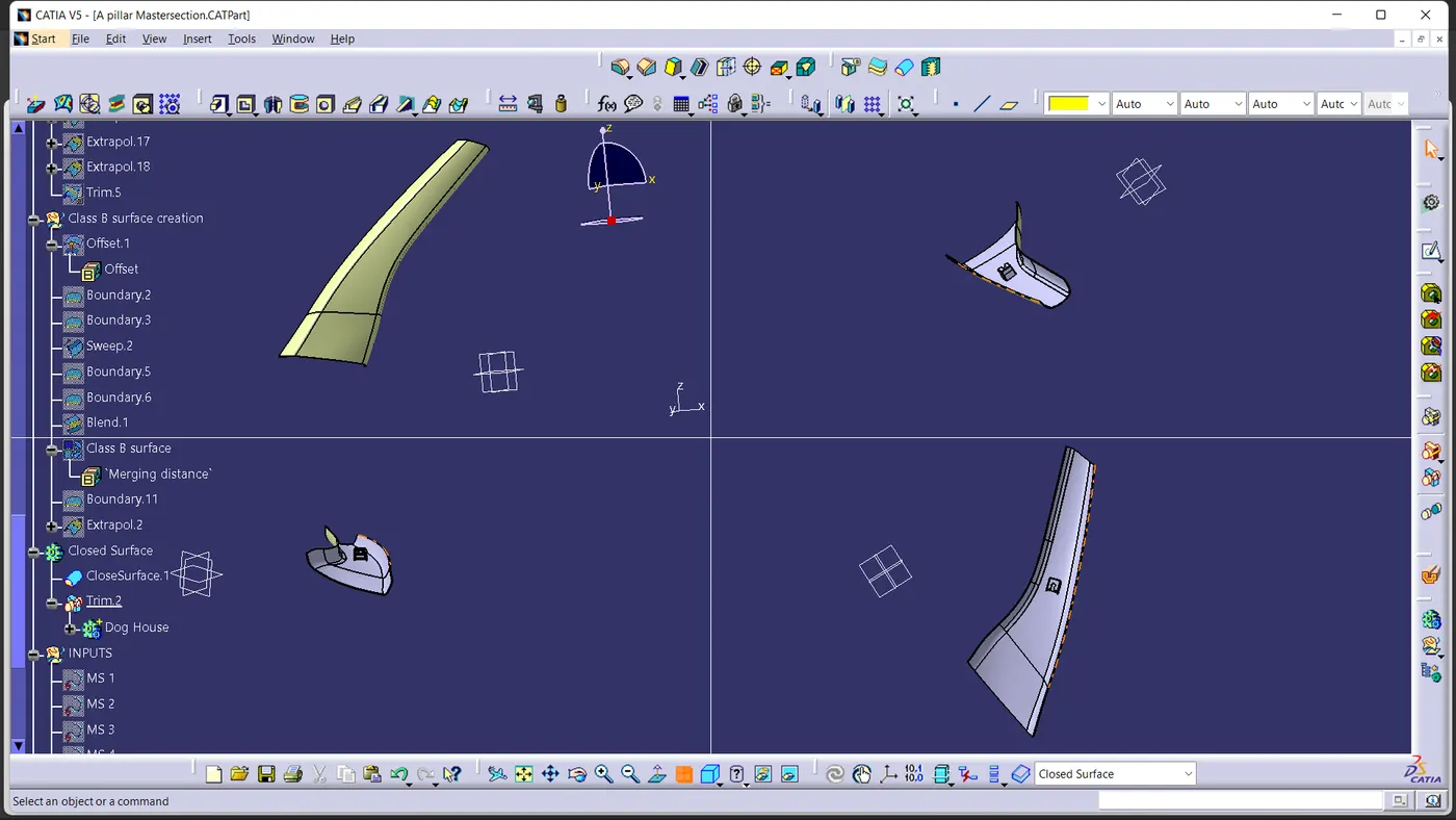
- Then the obtained surface is converted into solid using Close Surface and thus the final Door Trim Plastic Component is obtained. The image is shown below is A - Pillar Plastic component
CLOSED SURFACE:
DOG HOUSE:
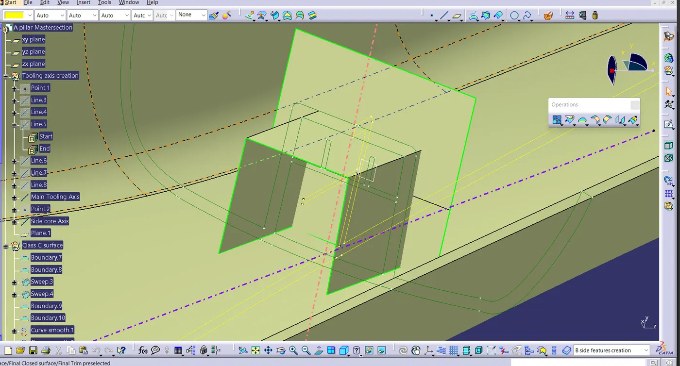
Dog house is an engineering feature used in plastic design. Dog houses are used as support feature. Sometimes other engineering features like snaps, locators, screw bosses are mounted on them to increase their strength.
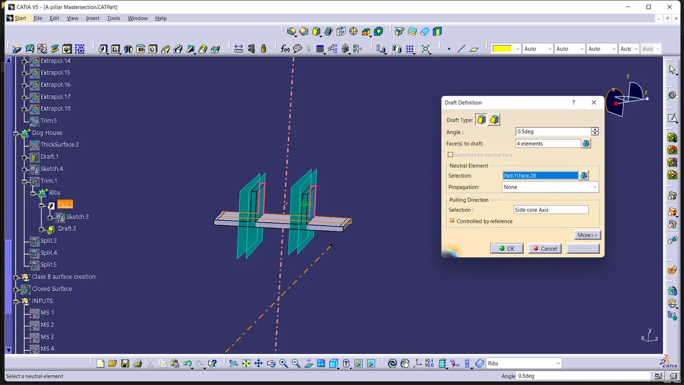
Dog houses are subjected to draft analysis to prevent breakage of the component during ejection from the mould cavity. Dog house and other engineering components are built on the B-surface
- Dog houses are designed to avoid SINK MARK created on the CLASS-A surface by screw bosses and to solve the length issues when giving screw bosses which need to be assembled to other components.
- It is also useful when perpendicular screw bosses are required on the part to the tooling direction.
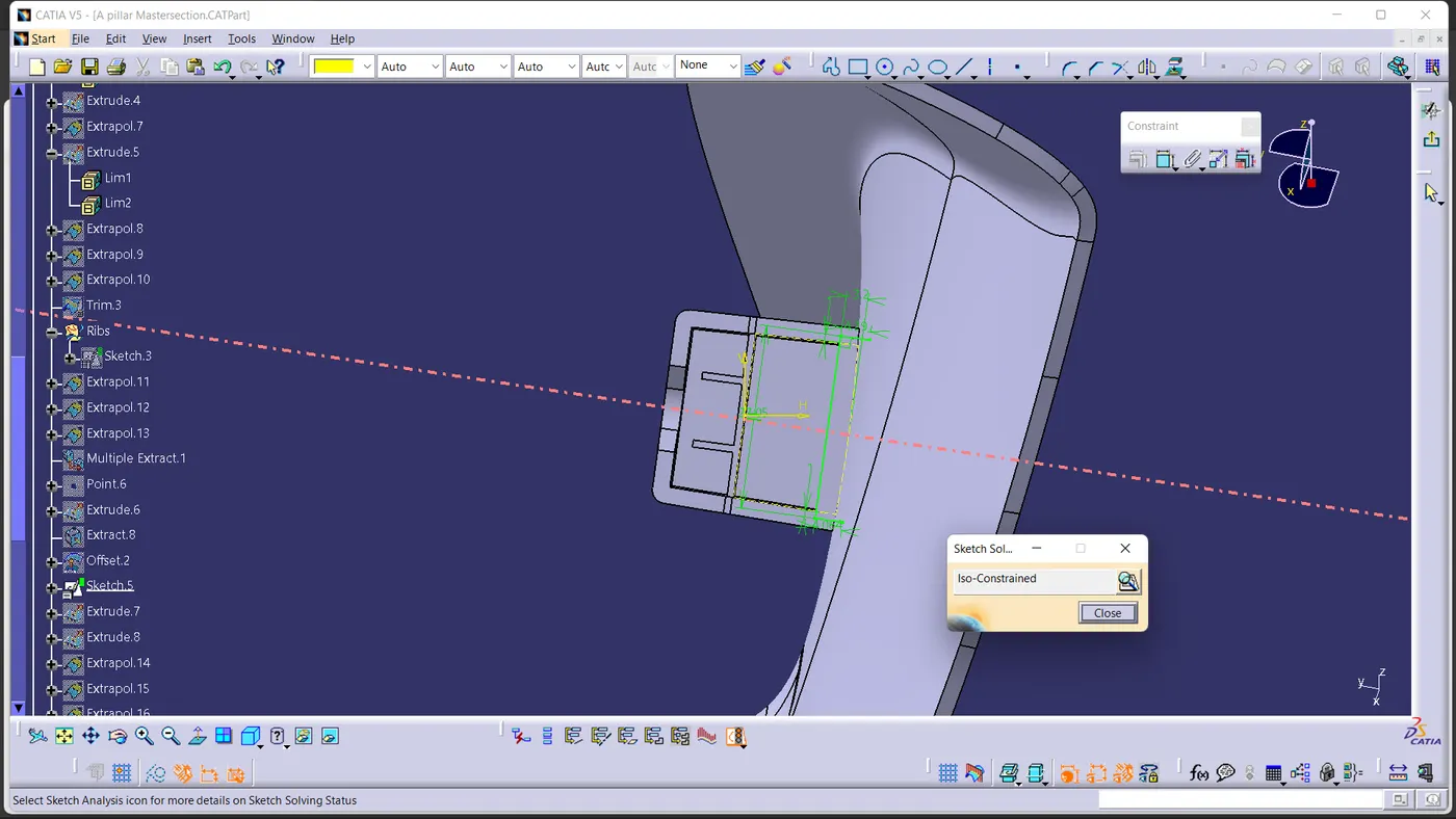
- Make a rectangle to enclose the screw boss in it but make sure it is open from one side.
- Sweep it with tooling axis as the pulling direction inwards.
- Close the top face by using multi section surface.
- Thicken it by 2.5 mm to the outward direction.
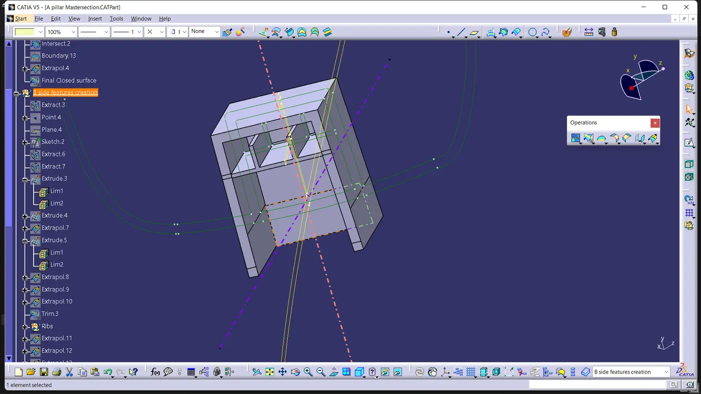
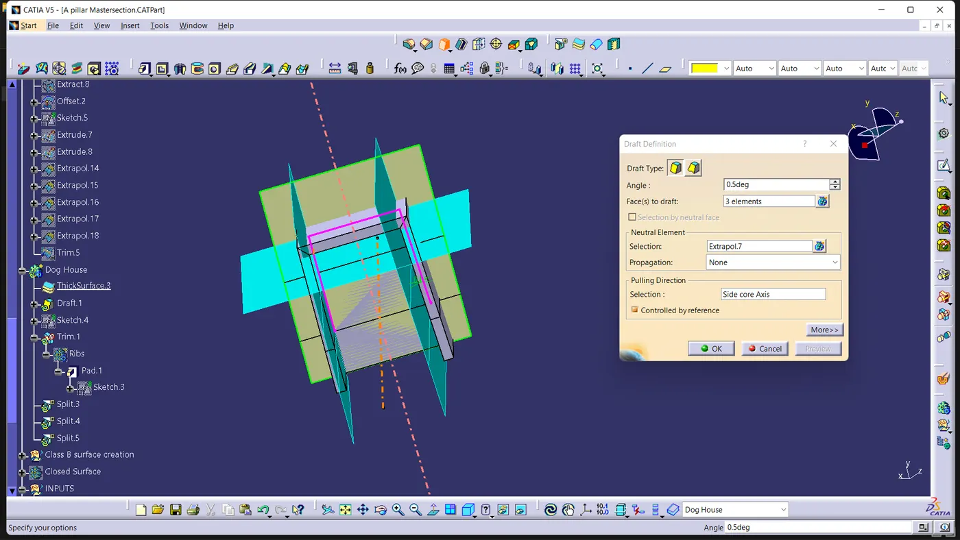
B Side Features Drafts:
DRAFT ANALYSIS:
Tree Structure:
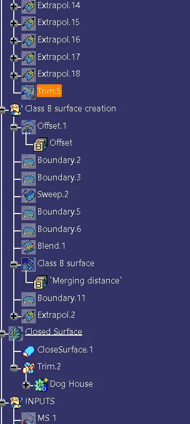
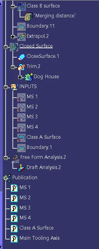
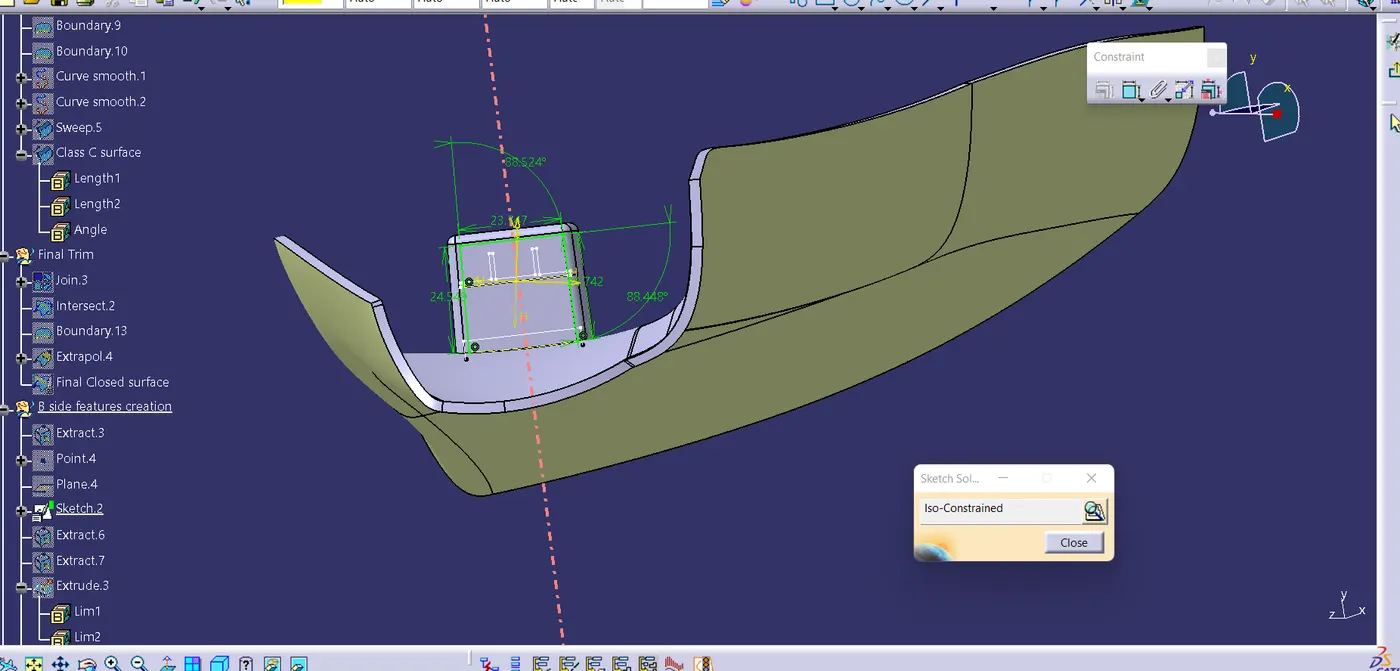
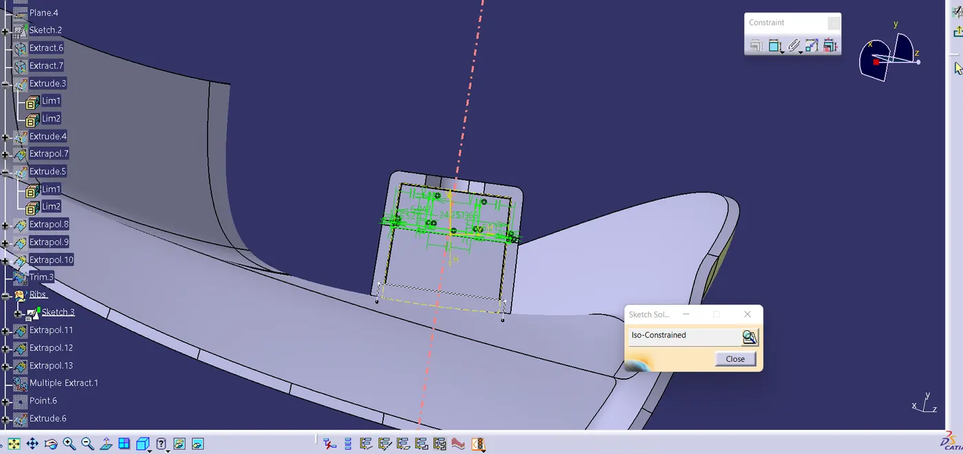
Sketches:
Different view of Final Body :
Conclusion:
Thus the A - Pillar Plastic component through the given Class-A surface and Master Section to create the B side features considering the design rules is created using Catia V5 software.