Week 11 - Project - A pillar Design with Master Section
week 11 challenge:
PROJECT 1:
A PILLAR section with MASTER SECTION.
AIM:
To create a A pillar design plastic component through a given class a surface and also create a doghouse on it.
software used:
catia v5 R20
procedure:
download the given class A surface, then open it on the catia v5.
CLASS A SURFACE:
using a boundary command in surface workbench, check whether it is joined properly or not.if not try to fix it.
here is shows the class A surface.

TOOLING AXIS:
creation of tooling axis . check for the plane which should be easy to create using injecton moulding and choose a hole slot or a plane surface .
then create a point in it and a dummy tooling axis. then, check for a parallel and slope surface. using a intersect command draw a intersecting line of x and y separately.
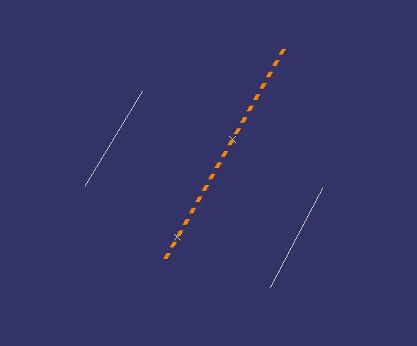
then draw a tooling axis for x and y separetely using a bisecting line . then draw a tooling axis as shown below.
side core axis:
extract the surface from the master section and create a line in it.

DRAFT ANALYSIS:
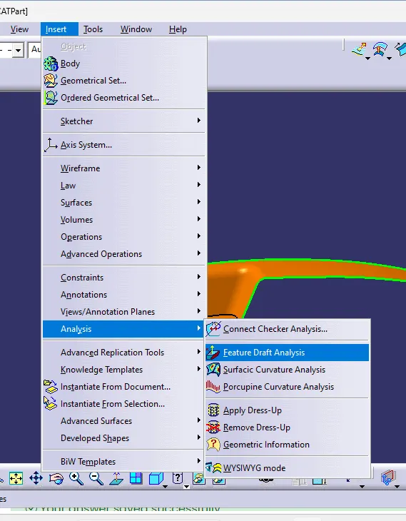
for draft analysis, in surface workbench click on insert>analysis>feature draft analysis as shown below:
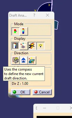
now click on compass to create c compass and place it on the tooling axis.
click on the class A surface to check the draft in the surface.
from the below figure it shows green which means it has a draft of more than three angle.
because less than three degree angle was difficult to manufacture.
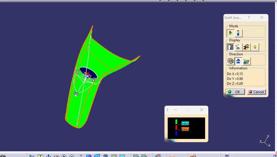
if the draft angle is less than three degree change the tooling axis angle or position and try it.
in this the degree of it is 3 degree.something where it cant be cleared.
SURFACE B :
for creating a class b surface. first extract a plane surface and then untrim it. now extrapolate the untrim portion . then trim to get a final output. and offset it to a thickness of the component.
for this challenge, it is directly offset to the thickness of 3mm.
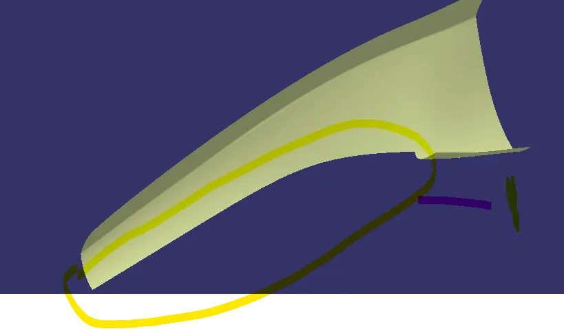
here only one patch is missing. it was cleaned by using the sweep command of expilicit with profile and guide curve.
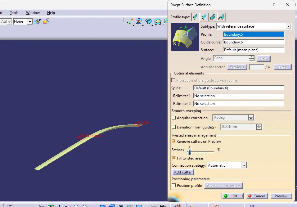
using join command join it.
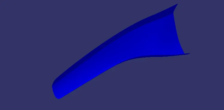
here it shows the CLASS B SURFACE.
note:
to check the clas B surface.create a boundary on it . if the booundary was along the corner it is perfect if not check it.
CLASS C surface:
creating a class c surface firstly create a boundary along the class a surface. then using a sweep command sweep it.
for this boundary four individual boundary are created and then join together.
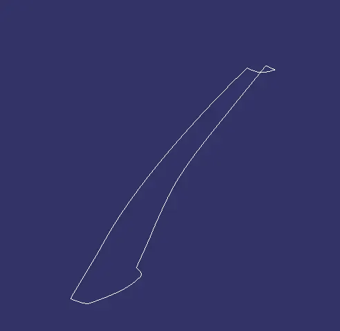
after creating a boundary, sweep it with draft direction as shown below for the surface.
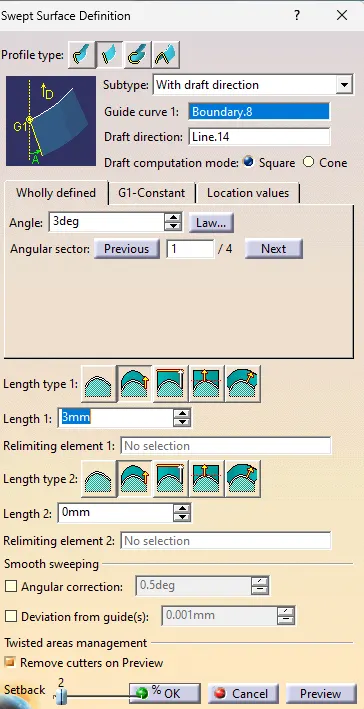
after sweep it is extruded, extrapolated and trim to obtain a joined surface.
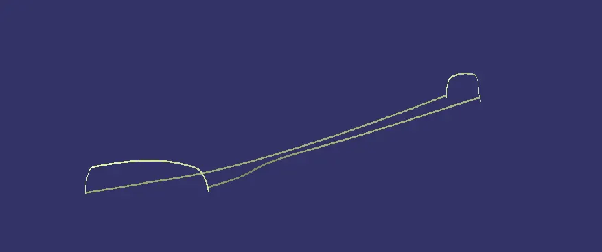
after creating a class c surface. using a trim command join the CLASS A and CLASS C surface to get a joined surface as shown below.
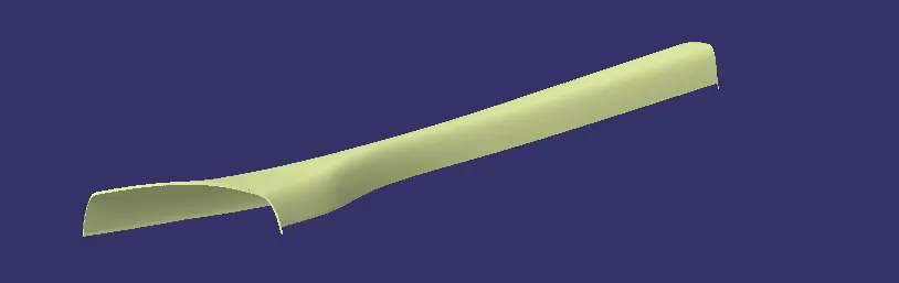
FINAL OUTPUT:
then trim the surface of A and C to the the classB surface to get a final output as shown below:
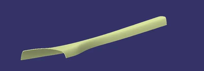
note:
create a boundary in the final trim. if it shows no boundary. then it is a closed surface.
else it has some open surface. patch it or fill the opens.
now, from the part design. create a solid body

FEATURE ATTACHMENT:
for doghouse:
it has three section, one with the bas, middle and top section.
base:
create a positioned sketch and draw the sketch as given below.
from the master, the sketch has been obtained and then it is pad and then provide a draft on the backside.
finally provie a fillet.
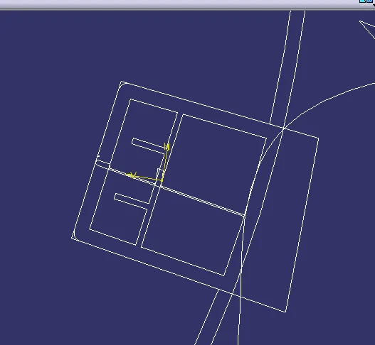
for inner portion:
create a sketch and take the projection of the inner.
elongated the line and closed the box with line.
now pad it to required dimension provide draft to the backside only with lifter axis as pulling direction.
provide neccesary fillet.
then using a boolean command remove it to the base to get a hallow dog house
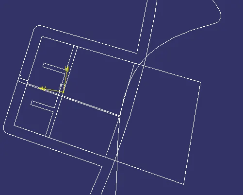
now to avoid sink mark create a hallow shape on the bottom.
by extract the class b surface and the face of the inner portion.
extrapolate the surface and trim it.
now provide draft and fillet then offset it with 1mm.
now in part workbench. using a split command split it with the doghouse.
for middle:
create a sketch and project the middle portion of the master section .
now pad it on a new part.
then provide fillet and draft, using boolean command union trim it with the doghouse.
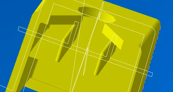
for top section:
create a new sketch in the top of the doghouse.
then draw a circle, rectangle and a two line.
circle with the dimension of 5mm radius.
then the angle for two lines are 45 degree and trim it and join with a line to create a closed sketch.
finally pad it and using boolean command remove it from the doghouse
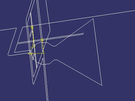
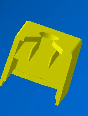
the final doghouse would look a like :
note:
here the doghouse is create with a box type. but in the given diagram it is in circle type.
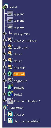
tree structure:
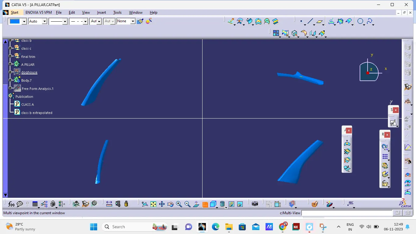
ALL views:
DRAFT ANALYSIS:
for draft analysis, in surface workbench click on insert>analysis>feature draft analysis as shown below:
now click on compass to create c compass and place it on the tooling axis.
click on the class A surface to check the draft in the surface.
from the below figure it shows green which means it has a draft of more than 1.5 degree angle.
for side core axis as a compass direction. it was obtained the below images.
inner portion draft with side core axis:
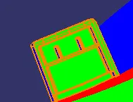
here, most of the region shows in the green color,
draft analysis for final component:
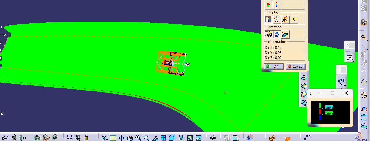
here the most portion shows in green color which has an angle more than 3 degree, some region shows in blue and red color.
ribs:
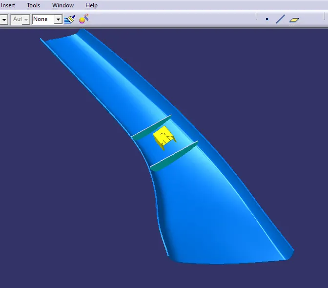
now for to provide a additional strength, ribs are created.
by drawing a line in sketch and extrude in the surface workbench.
then thick command to thick it and finaly provide the fillet and draft.
conclusion:
from the above, Created the A pillar trim Plastic component and doghouse is done through the given Class-A surface.
the catpart file is attached below.
==================================================================