Week 11 - Project - A pillar Design with Master Section
AIM :
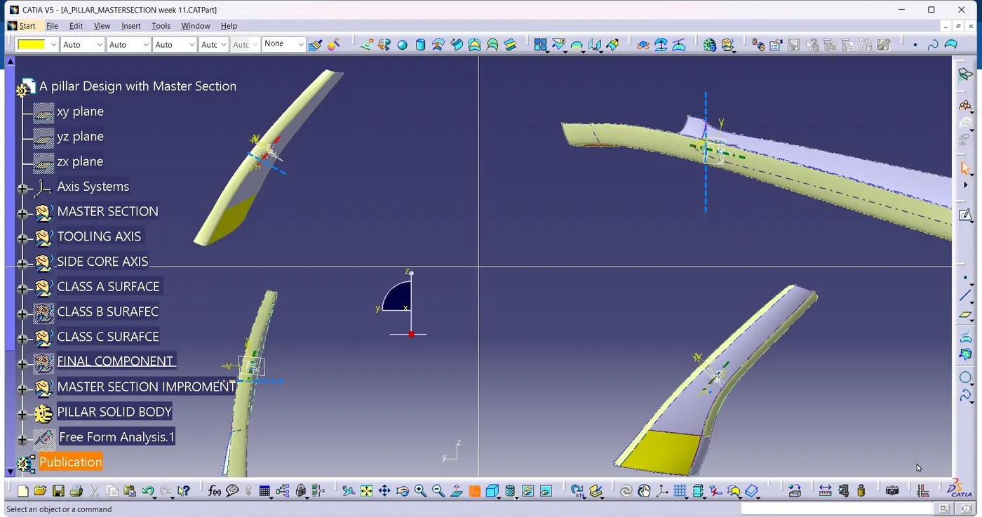
To create the A pillar design with the master section and given intersection sketch with class A surface and create thetooling axis, To perform the draft analysis for the final part.
CLASS A WITH MASTER SECTION :
Visible surface is a class A surface. It provide the austhetic surface look for the component, Which the part design engineer uses to develop the components with the all engineering requirements. Check the continuity for the given surface using join or boundary commands.
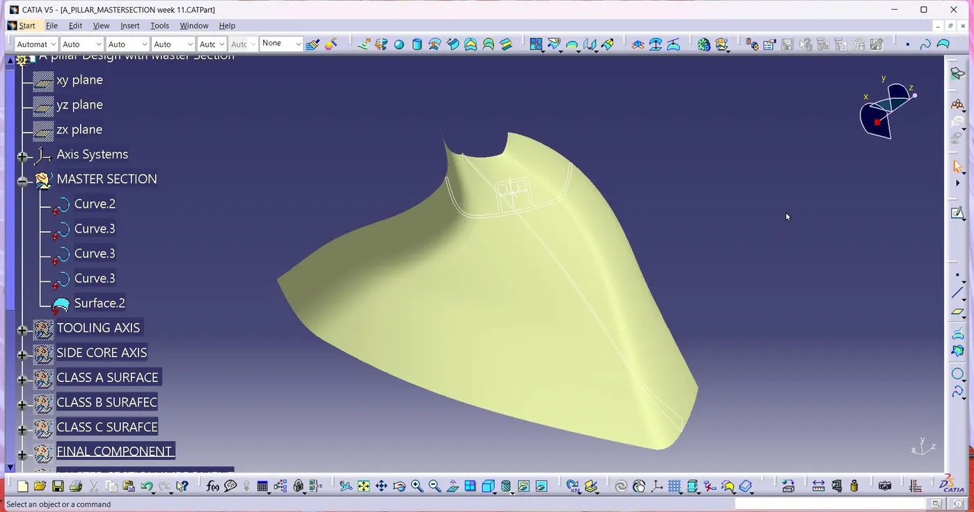
TOOLING AXIS :
Using the dummy axis, the bisecting line method is essentially used to identify the correct tooling axis. when using the bisecting line method a line is utilized to either bisect the two lines or indicate an error, indicating that the two lines are parallel. we intersect the surface with yhe appropriate plane to determine whether or not the surface is toolable. This produce a drawing with two lines, which we can then biset to provide a third line at the intersection of two lines.
SID CORE AXIS :
Using the bisecting line method or crate using the given master section create the side clearence axis for the dog house.
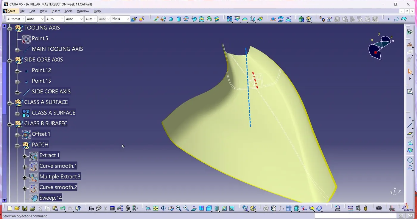
CREATE THE CLASS B SURFACE
First offset the surface to 2.5mm, some patches are comming then we will do the clear the area. Then, We use to boundary, sweep, extrpolate, and trim and join to close the surface. Join tall ogether.
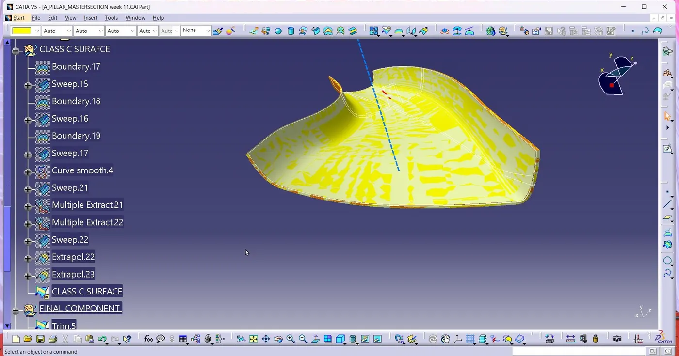
CLASS C SURFACE
At first extract the boundaries of the class A surface and B surface and use the sweep option to create the C surface.
DOG HOUSE :
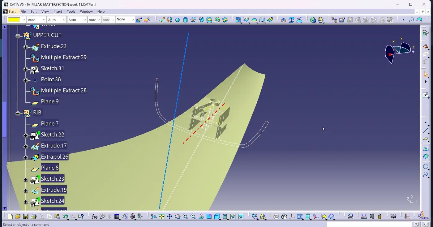
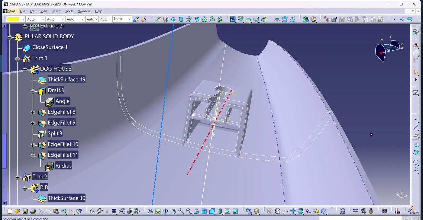
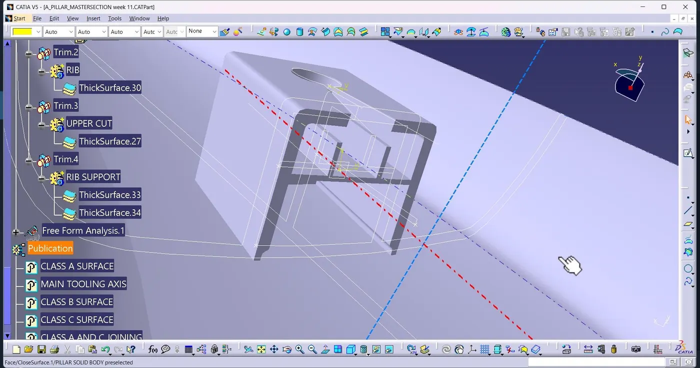
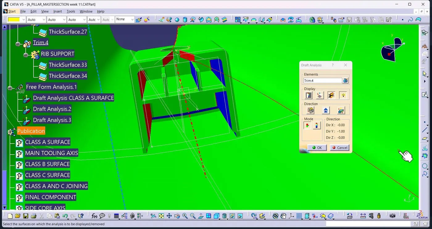
A plastic design element called a DOG HOUSE is employed. Dog house are a supporting element. In order to strengthen their robustness, snaps, locators and screw boss may occasionally be put on them. Draft analysis is applied to dog house to minimize components broken during the ejection from mould chamber. On the B surface, a dog house and other engineering elements are construted.
DOG HOUSE CREATION :
Dog house are made to prevent the SINK MARK that screw bosses leave on class A surface and to address the length problems that rise when attaching screw bosses to other components.
it is especially helpfull when the part needs screw bosses that are perpendicular to the direction of toolling.
C thickness should be 40‰ of the main wall thickness T
Minimum width of the dog house is 12mm
Height of B should be 3-6 mm
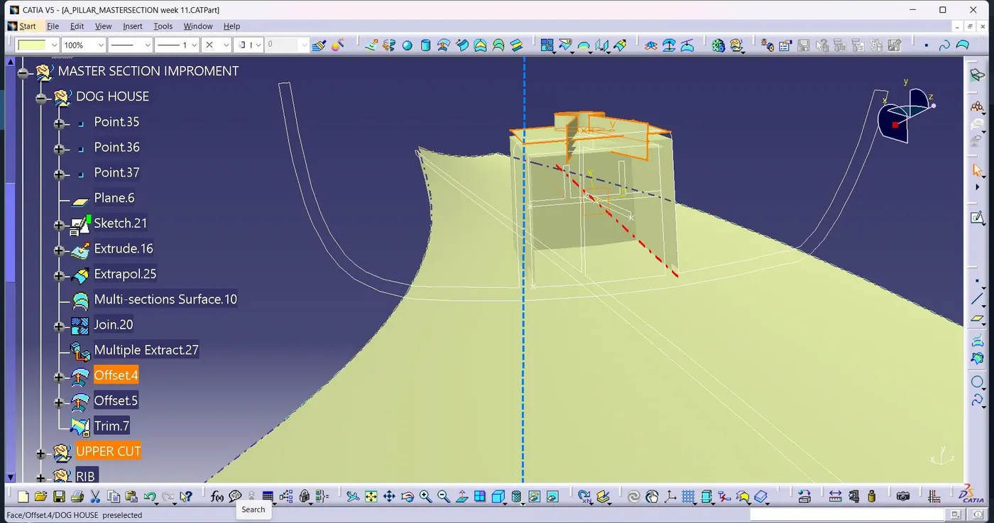
Final draft analysis :
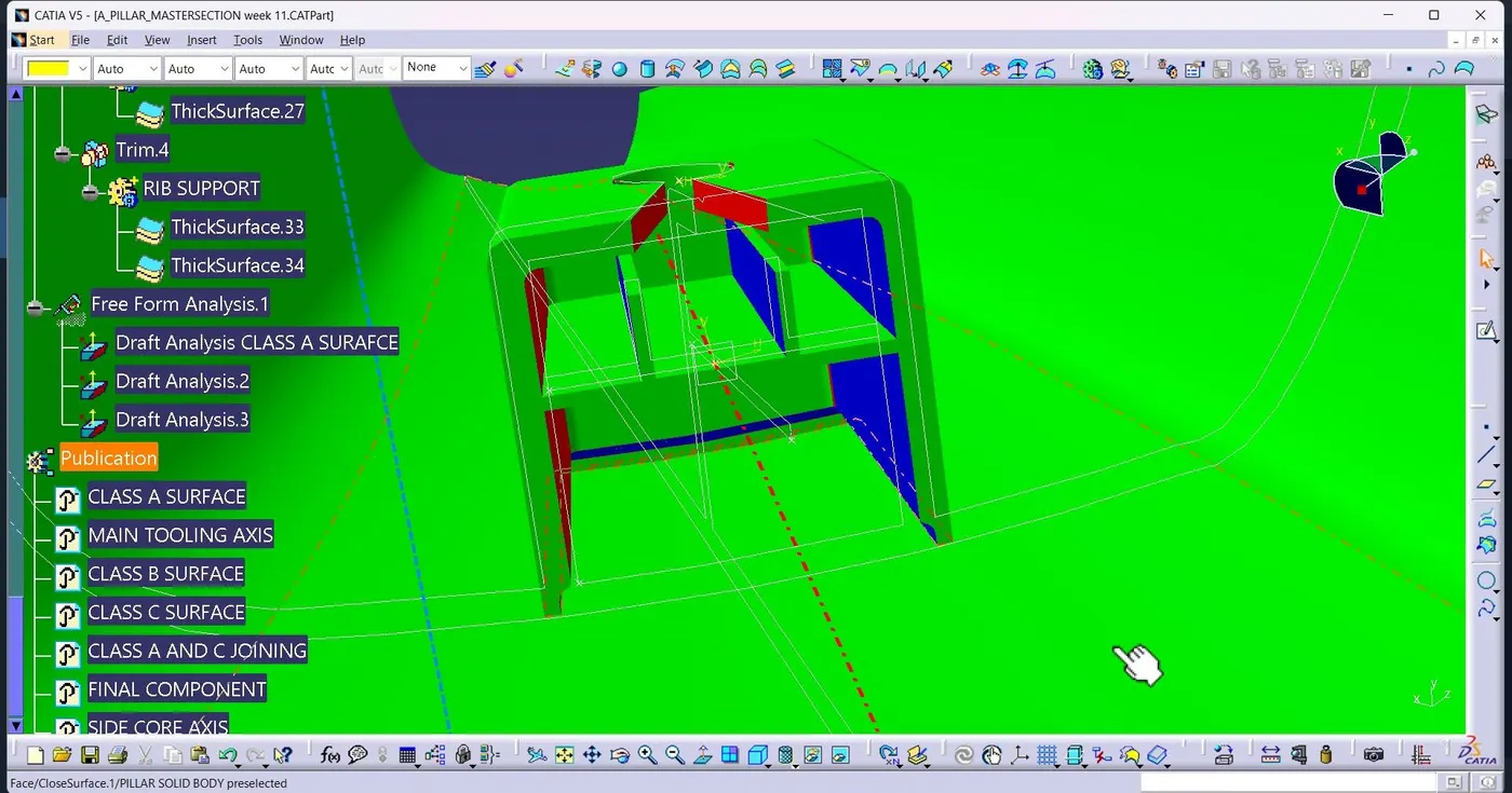
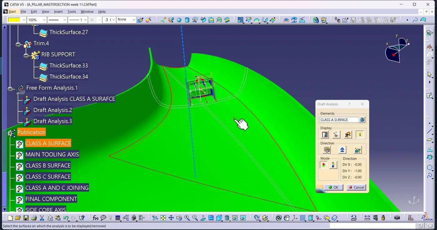
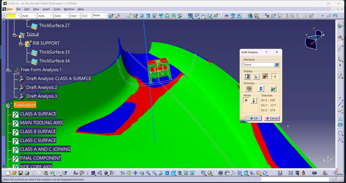
Use the featured draft analysis tools to now analysis the draft. After locating the compass and aligning it with the tooling axis, xlick on the lock symbol after aligning, and then click again on the surface after opening the draft analysis tool box. Do this for both the axis and analysis for dog house.
CONCLUSON :
Finally, we done the design using all engineering feature and requirement with dog house.