Week 11 - Project - A pillar Design with Master Section
AIM-:
- CREATE THE PROPER TOOLING AXIS.
- DRAFT ANALYSIS OF CLASS A SURFACE.
- CREATE THE CLASS B AND CLASS C SURFACE.
- CREATE THE SOLID BY USING GENERATING SURFACE.
- CREATE THE DOG HOUSE, PROPER ALIGNED WITH SECTION LINE.
- DRAFT ANALYSIS OF DOG HOUSE AND FINAL PRODUCT.
- ATTACH ALL THE SNAP SHOTS REAGARDING ALL.
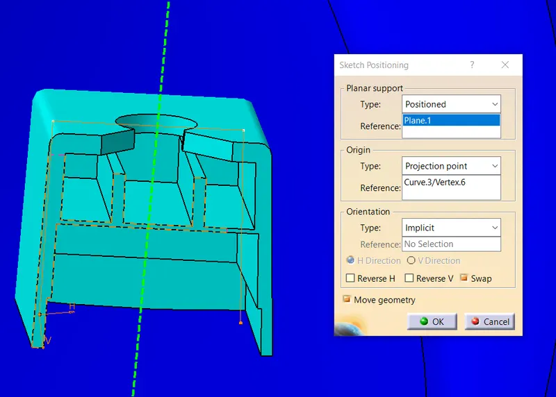
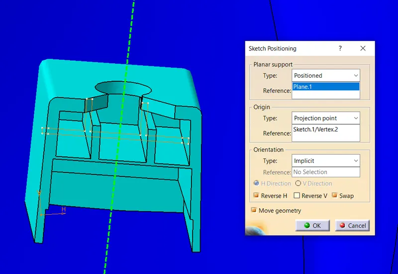
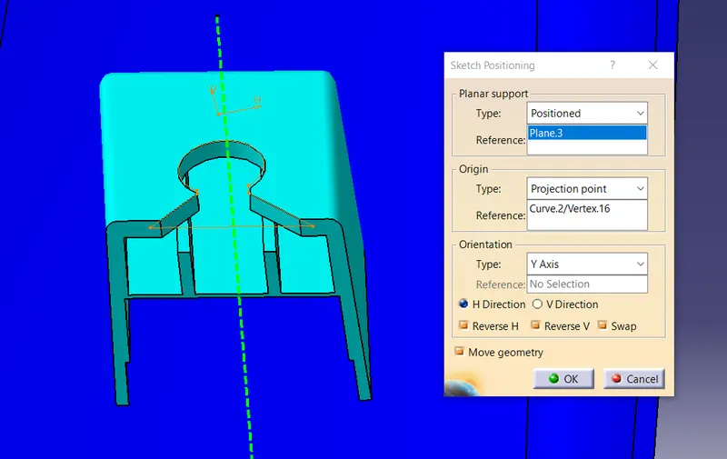
1. POSITION SKETCH
- All sketches were created by using position sketch.
A) DOG HOUSE SKETCH POSITION IMAGE
B) DOG HOUSE MIDDLE FLANGE SKETCH POSITION IMAGE
C) DOG HOUSE UPPER CUTOUT PORTION SKETCH POSITION IMAGE
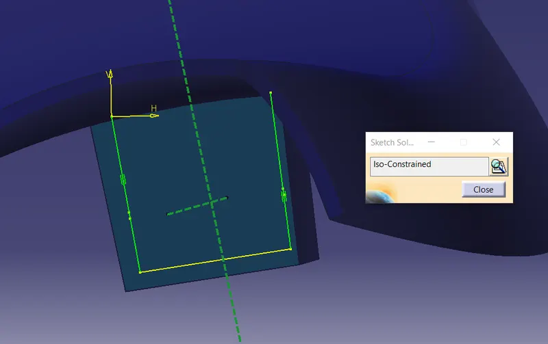
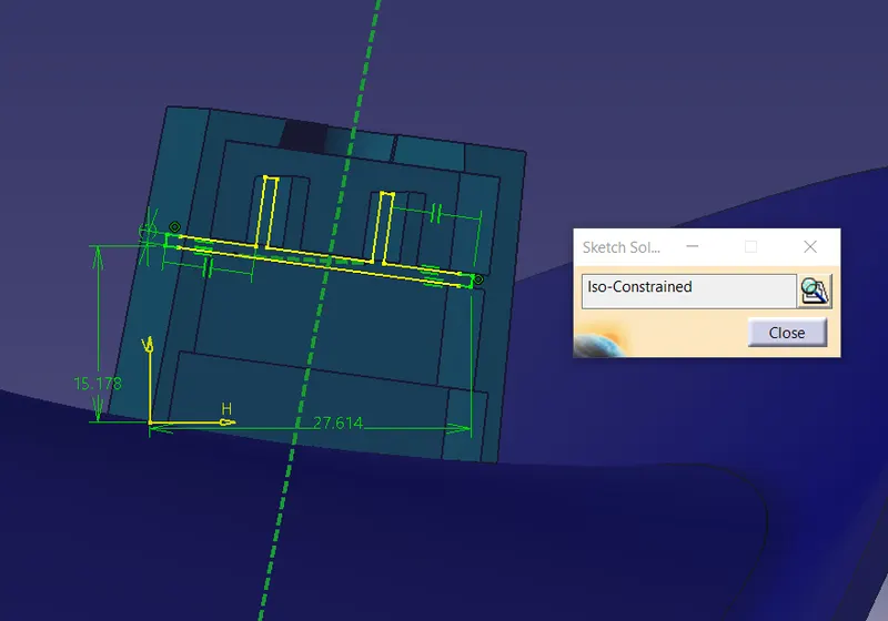
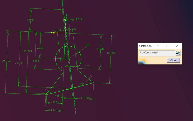
2. ISO-CONSTRAINED
- All sketches where created with proper dimension and also follow ISO-Constraint sketch solution.
A) DOG HOUSE SKETCH SOLUTION IMAGE
B) DOG HOUSE MIDDLE FLANGE SKETCH SOLUTION IMAGE
C) DOG HOUSE UPPER CUTOUT PORTION SKETCH SOLUTION IMAGE
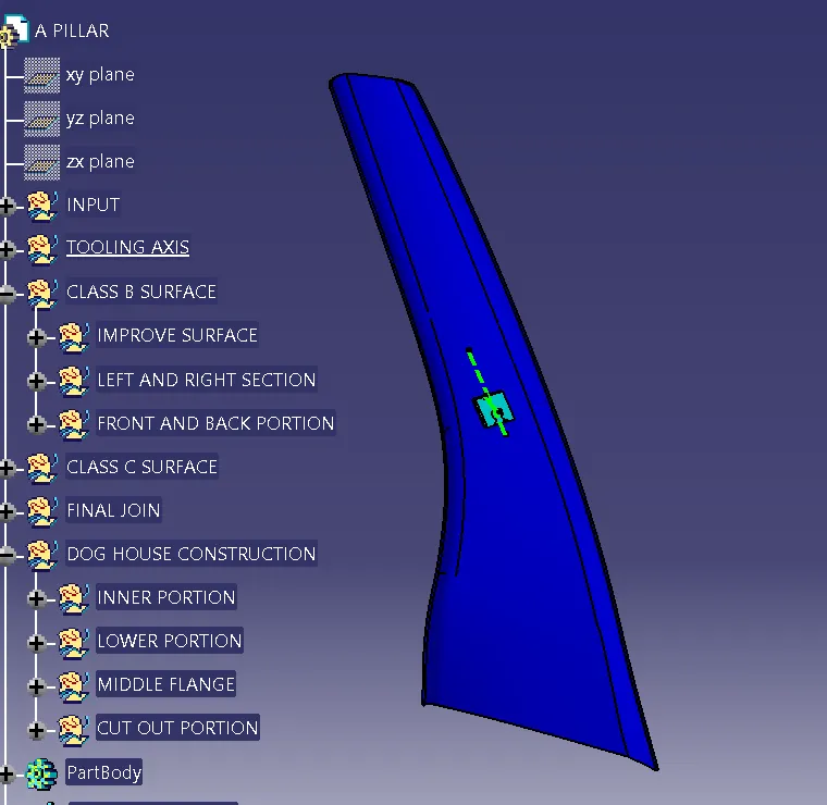
3. TREE STRUCTURE
- Tree structure created with proper name.
A) PROPER TREE STRUCTURE
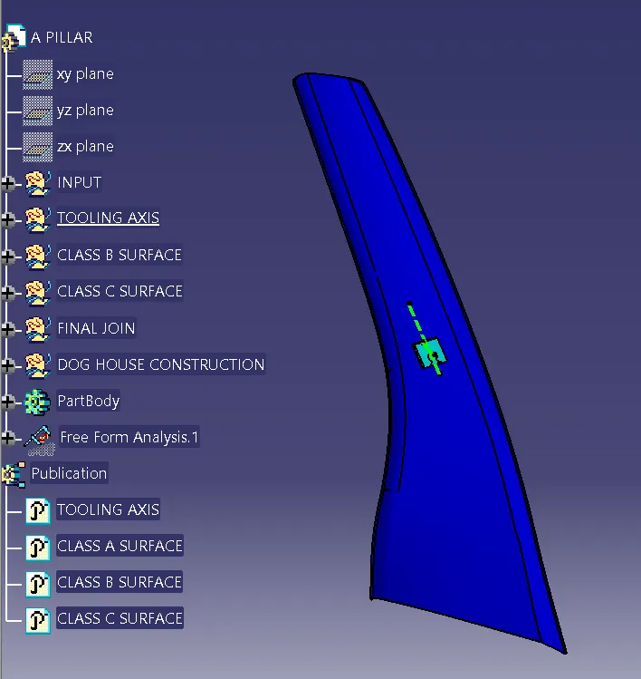
B) DETAIL TREE STRUCTURE
- Geometrical set are created with proper name inside it.
- All sketches were created in the geometrical set.
4. TOOLING AXIS
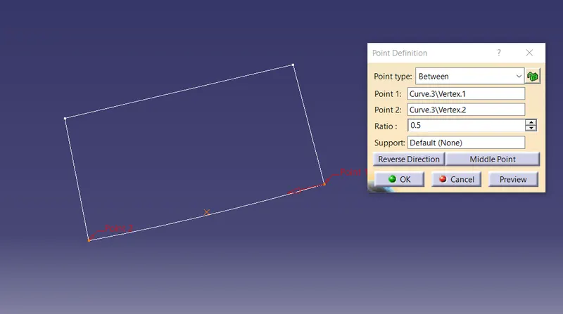
- Choose "Point" command in "Wireframe" toolbar.
- Choose "between" option in "Point type".
- Select Point 1 and Point 2 from given intersection sketch.
- Choose "Middle point" option.
- Click ok, Point is automatically created between two point.
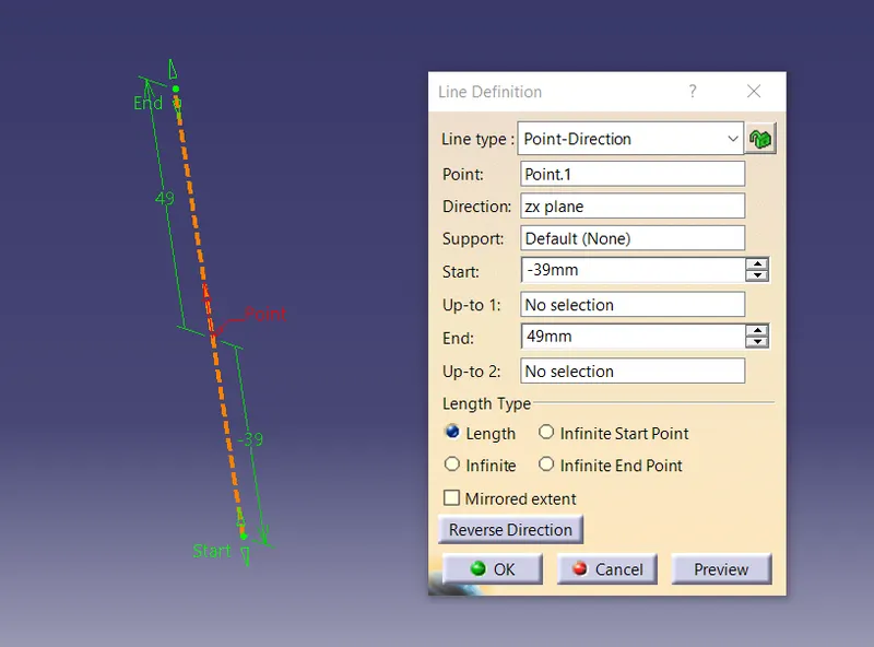
- Go to the "Line" command in "Wireframe" option.
- Choose "Point-Direction" option in "Line type".
- Select the point.
- Select the "ZX Plane" in "Direction" option.
- Put the value of Start and End limit.
- Click ok, Tooling axis is created automatically.
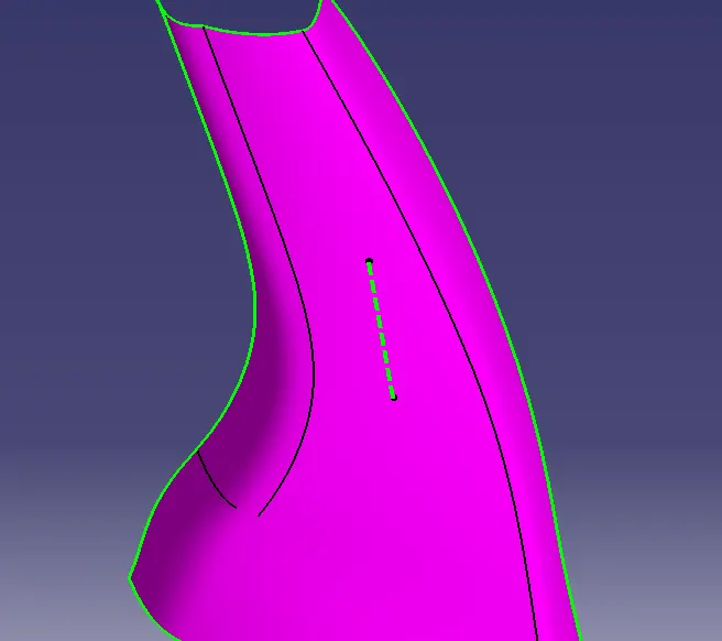
- Right click on "Line" and choose "Properties" option.
- Choose "Feature Properties" option and give name as Tooling axis.
- Change the colour of the line, increase the thickness and choose hidden line for proper view of Tooling Axis.
5. DRAFT ANALYSIS OF CLASS A SURFACE
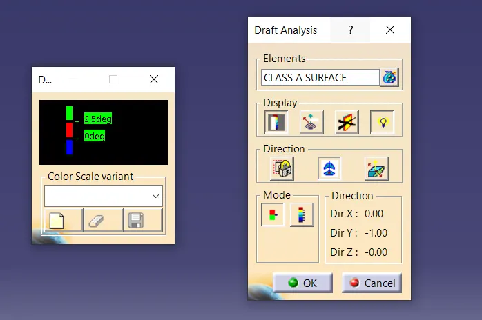
- Go to "Insert" toolbar, then choose "Analysis", then choose "Feature Draft Analysis".
- Select "CLASS A SURFACE" in "Elements" option.
- Choose "Shows or hide the color scale" in "Display" option.
- Deselct the "Analysis under the running point" if you don't want to check the running point angle.
- Select "Uses the compass to define the new current draft direction" option.
- Drag the compass and placed it in Tooling axis line vertically.
- Choose "Inverses the draft direction" option as per required.
- Choose "Switch on the quick analysis mode".
- Enter the draft angle value by double clicking on it.
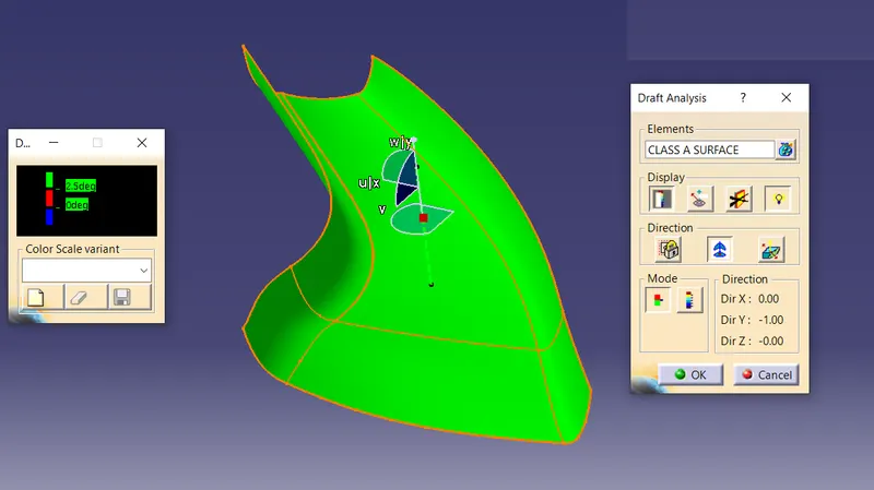
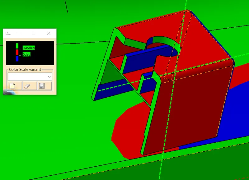
RESULT-:
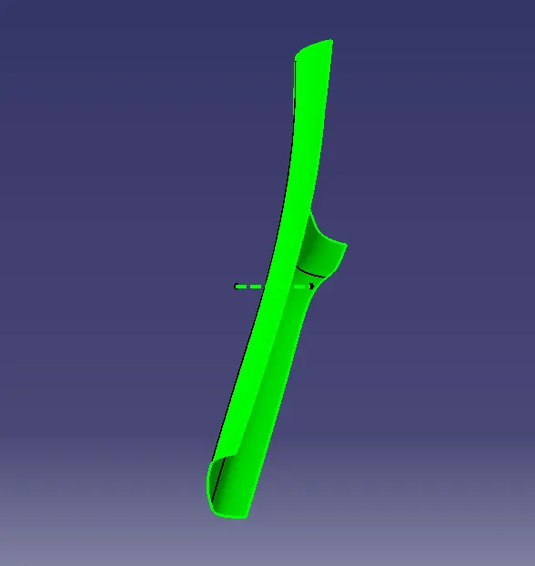
- If "CLASS A SURFACE" show green colour in top side, it means it created with proper draft angle in limit and no further correction required for this surface.
- If "CLASS A SURFACE" show Red or Blue colour in top side, it meand the draft angle is not given in limit and then correction or working is required on this surface and Design Enginner will not consider this surface design for manufacturing.
A) ISOMETRIC VIEW
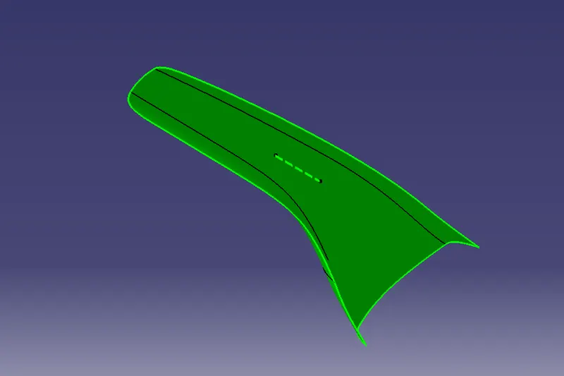
B) FRONT VIEW
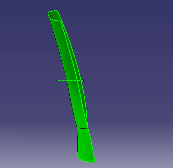
C) SIDE VIEW
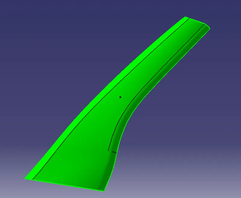
D) TOP VIEW
E) COLOUR SCALE
6. SOLID BODY
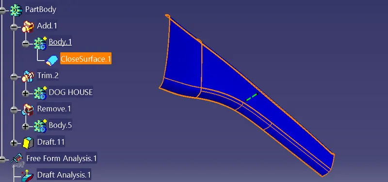
- Surface command is used to make the class b and class c surface.
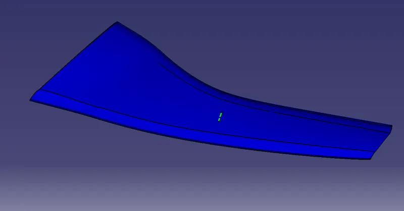
- Solid body command is used to create the A Pillar as per master section.
6. DRAFT ANALYSIS OF FINAL PRODUCT
- Go to "Insert" toolbar, then choose "Analysis", then choose "Feature Draft Analysis".
- Select "PART BODY" in "Elements" option.
- Choose "Shows or hide the color scale" in "Display" option.
- Deselct the "Analysis under the running point" if you don't want to check the running point angle.
- Select "Uses the compass to define the new current draft direction" option.
- Drag the compass and placed it in Tooling axis line vertically.
- Choose "Inverses the draft direction" option as per required.
- Choose "Switch on the quick analysis mode".
- Enter the draft angle value by double clicking on it.
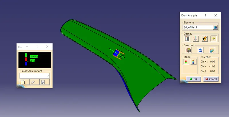
RESULT-:
- If "PART BODY" show green colour in top side, it means it created with proper draft angle in limit and no further correction required for this surface.
- If "PART BODY" show Red or Blue colour in top side, it meand the draft angle is not given in limit and then correction or working is required on this surface and Design Enginner will not consider this surface design for manufacturing.
A) ISOMETRIC VIEW
B) FRONT VIEW
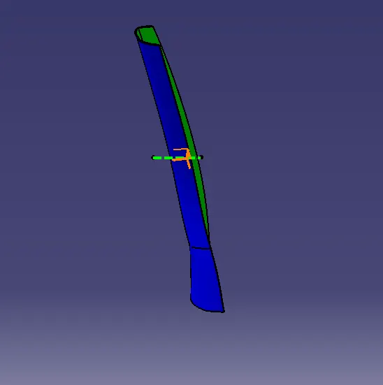
C) SIDE VIEW
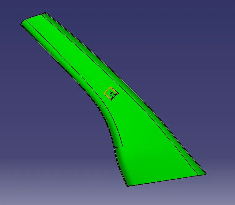
D) TOP VIEW
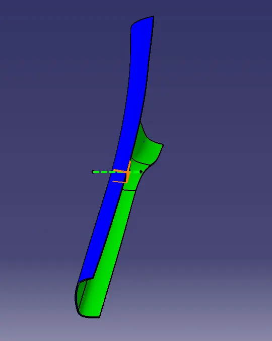
E) COLOUR SCALE
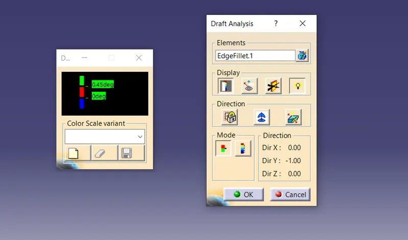
F) CRITICAL SECTION
a) DOG HOUSE BACK PORTION
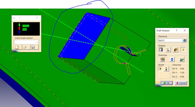
b) DOG HOUSE INNER LEFT PORTION
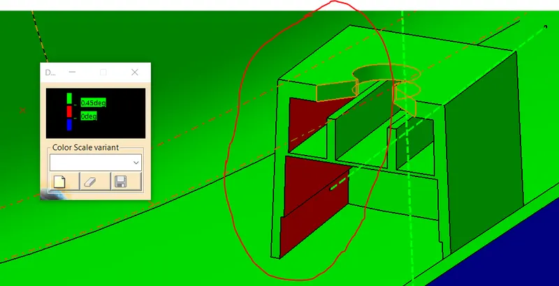
c) DOG HOUSE INNER RIGHT PORTION
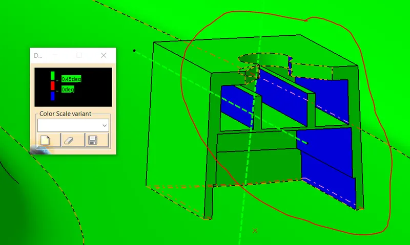
7. DRAFT ANALYSIS OF DOG HOUSE BY SECOND TOOLING AXIS
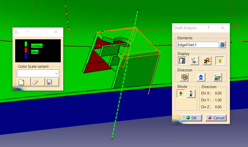
CRITICAL SURFACE
a) DOG HOUSE UPPER, LEFT AND RIGHT PORTION
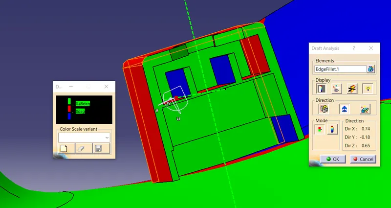
b) DOG HOUSE UPPER, LEFT AND RIGHT PORTION