Week 11 - Project - A pillar Design with Master Section
AIM: To design A - Pillar using the given Class A Surface.
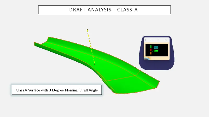
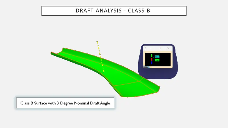
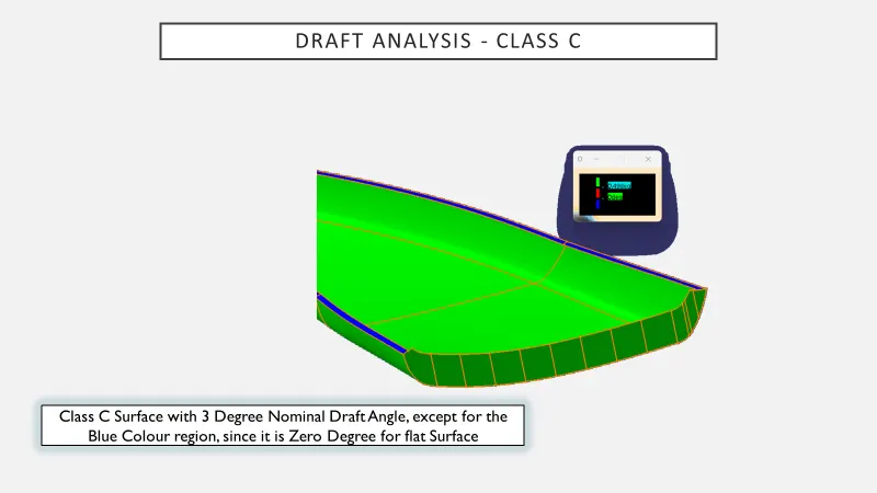
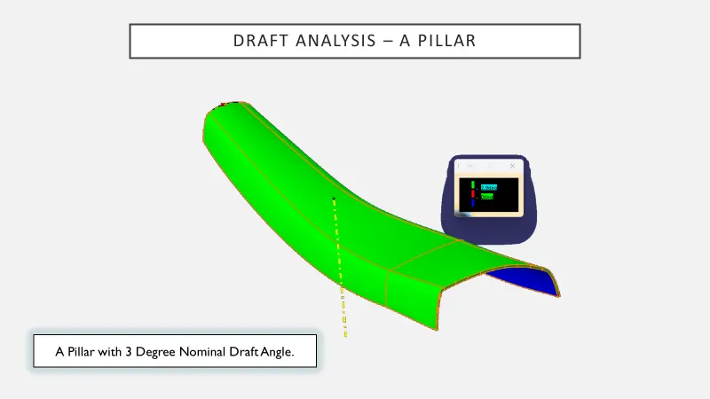
Draft analysis: Draft analysis refers to the evaluation and examination of designs or technical drawings to assess their suitability for manufacturing or construction purposes. It involves analyzing the dimensions, tolerances, geometry, and other specifications of a design to ensure its functionality, manufacturability, and adherence to industry standards.
To evaluate the component, we must follow the steps below.
Step 1:
- Verify the Connectivity of the Class A Surface to Make sure there are no gaps between the components by using the join command.
- Perform a visual inspection or click on the boundary command and obtain the boundary lines of the component.
In our case, the component consists of a single boundary. As a result, the initial check has been completed.
Step 2:
- Determine the Tooling Axis of the Component The tooling axis refers to the direction in which the mold or cavity opens.
- Evaluate visually to identify the most suitable tooling axis.
- Examine all three axes.
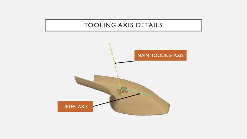
Since we have master section in our case, we will use the same to create the tooling axis, side core axis or lifter axis.
Step 3:
- Create the tooling and lifter axis with the help of master section.
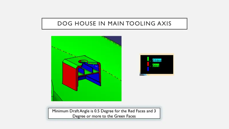
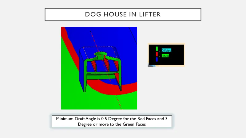
- Perform a Draft analysis using the Featured Draft Analysis tool in the software.
- Open the draft analysis toolbox.
- Locate the compass tool and place it aligned with the tooling axis.
- Align the compass precisely and click on the lock symbol to secure its position.
- Click on the surface you want to analyze or apply the draft to.
In this challenge bisecting method is used to create the tooling and the lifter axis.
EXPLANATION OF BISECTING METHOD:
- The bisecting method is used to find the proper tooling axis using the dummy tooling axis.
- In Bisecting method, the bisecting line is used which either bisects the two lines or it will show an error which means the two lines are parallel to each other.
- To determine the tolerability of a specific surface, we intersect it with the respective plane, resulting in a sketch consisting of two lines.
- Using the bisecting line option, we then bisect the line, creating a line at the midpoint between the two lines. This process helps us assess whether the surface is tolerable or not.
- Similarly, we create tooling clearing axes for both the x and y directions. These axis are then utilized to establish the main tooling axis by employing the bisecting line option within the line command.
Since we have the master section, we have used the projections of the master section without need of x, y and z axis to create the tooling and lifter axis.
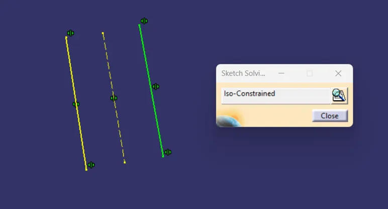
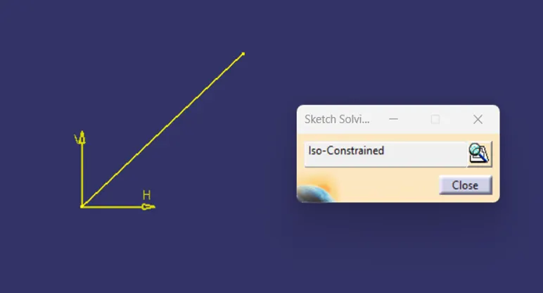
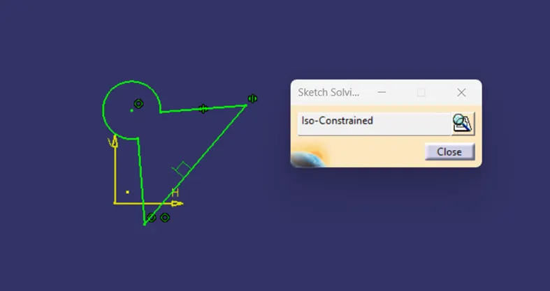
A. Picture of the sketches with Sketch solving status’s geometry tab
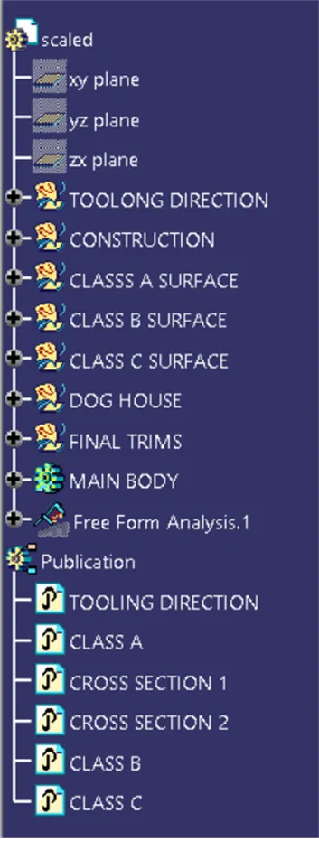
B. Picture of the Detailed tree structure.
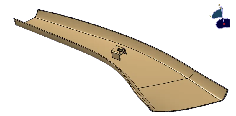
C. Picture of the 3D CAD and Closed Body
D. Create a tooling axis and follow design rules.
DRAFT ANALYSIS