Week 11 - Project - A pillar Design with Master Section
Week 11 - Project - A pillar Design with Master Section
Aim :
To create the A Pillar Design with the master section given as the intersection sketch with the Class A surface and create the tooling axis and perform the Draft analysis for the final solid part.
Objective :
- Create the required Tooling axis by using master section and bisecting methode.
- Design the Class-B and Class-C surfaces and close all three surfaces.
- Design the Dog house and its internal parts as given Drafts and mater section sketch.
- Draft analysis for the final solid part and side core Draft analysis.
Theory :
Tooling Axis :
Class-A surface is first analyzed to create the tooling axis or tooling direction that molds pull apart in injection molding. Tooling direction is important for plastic product design as it decides direction for mold seperation.
Step followed for creation of tooling axis :
- Reference point is first created on extracted surface.
- New axis system is deployed to plot clearance lines.
- The X-direction and Y-direction along the class-A were used to create tooling axis.
- Graphic properties of tooling axis were change before publishing.
Draft Analysis :
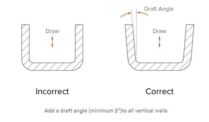
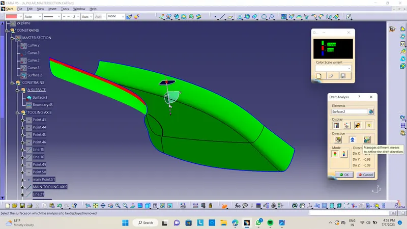
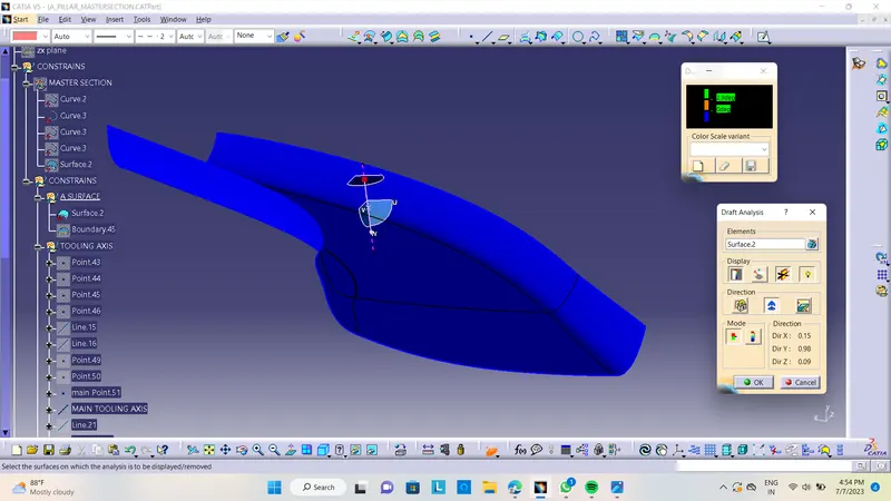
The Draft angle is the amount of taper for molded or cast parts perpendicular to the parting line. It can be measured in degrees. A functional part for injection molding has to have Drafts facing both cavity and core sides to reduce the risk of damage to the parts and ensure ejection. And also important is to overcome the vaccume forces by letting air in between the metal to the plastic for the part to relaese properly. Adding maintaining a decent cosmetic finish.
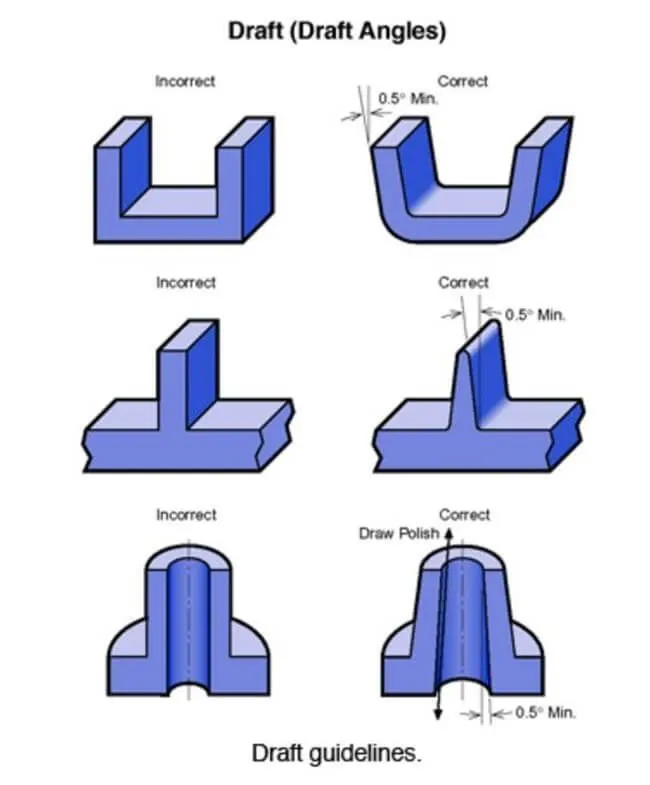
Draft should be a part of design for manufacturing and plastic product Designer should be aware of its need at the outset of the design process. This allows considerations for design requirement to be taken into account.
Nominal values for Draft angle :
- 3 Degrees is the nominal Draft angle.
- 7 Degrees for textured surface.
- At the minimum of 0.5 Degrees can be manufactured by special tools. But it will increase the manufacturing cost.
Tooling Axis Creation :
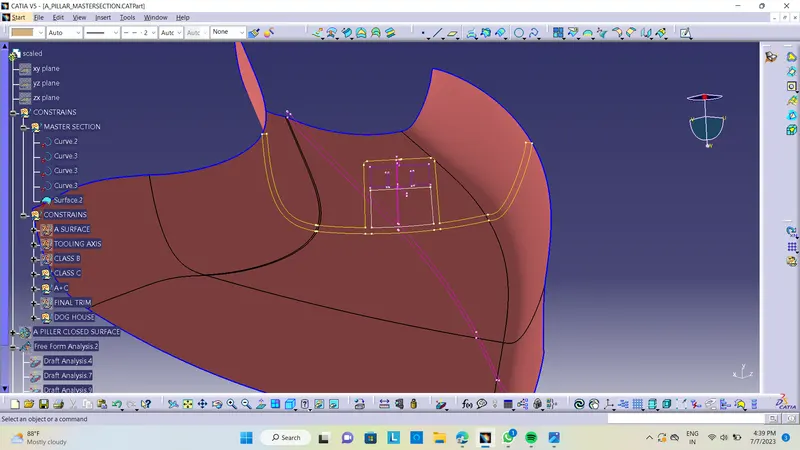
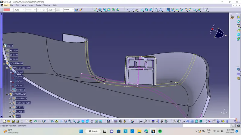
For this part tooling axis creation is done by using the mater section which is given along the Class A surface. Because in this master section the Dog house is there and the Draft for the wall of the Dog is given by the tooling axis. So can take tooling axis from the master section. This master section and Class A surface is given below.
ANSWER:
Master Section :-
- Master Sections are the guides for design requirements which shapes the component after technical styling of Class A Surfaces.
- Master sections are the guides for design requirements that decide the component packaging after technical (Styling, Concept, or Class-A) surfaces. Creating this master section should need 5 to 6 years of experience.
- This helps you to decide the feasibility, clearance, packaging, and fixation strategy before working it on a 3D. We have a master section.
- SNAP_1 :- Checked Class A with Boundary line.
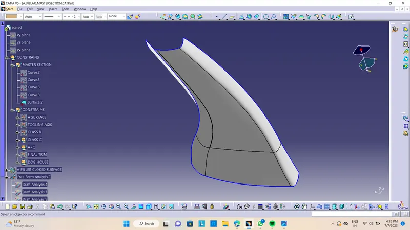
SNAP_2 :- Multiple master section
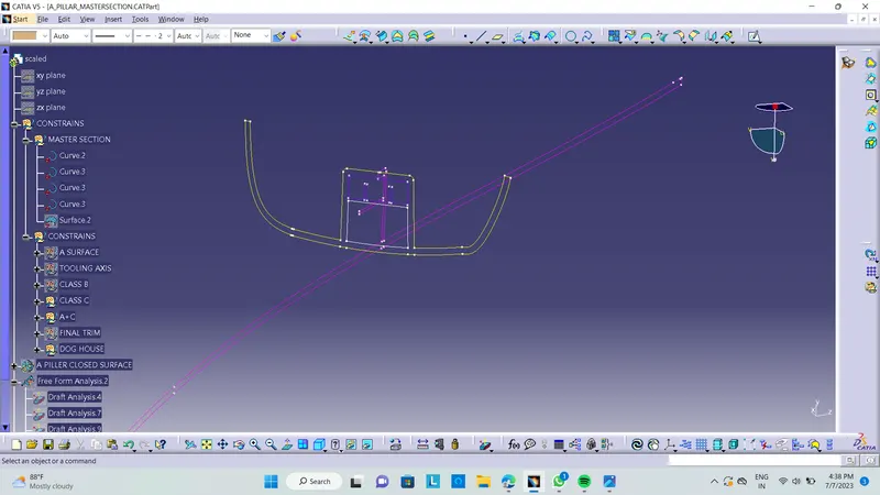
SNAP_3 :- Class A with Master sections
PROCEDURE_1 :- Creation of Tooling Axis
Tooling Axis :- In injection molding, the Class A surface is first analyzed to determine the axis or tooling direction that separates the molds. Tooling direction is critical for plastic product design because it determines mold direction. It is a main axis towards the direction the component ejject with also an core & cavity open or close.
The tooling axis created here with the reference of a master sections.
- First we need to create a point, point defination as a between.
- The point created between the 2 line point selected from the master section.
- After the point creation extract the 2 lines which are from the 1st master section. & hide the same master section as well for the better crearance view.
- Then this 2 lines has extraced used as a referance line for the creation the 1st Bisecting line.
- The same procedure are used for creation the another 2nd line from the 2nd master section repectively.
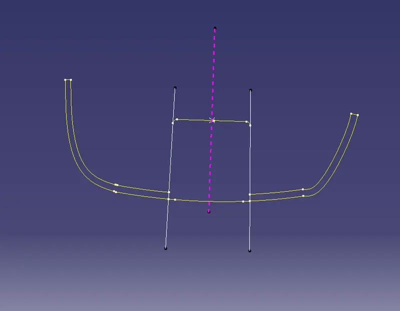
- Here we got a 2 Bisecting line in which we need to create a common line that is bisecting method again 7 finally we get a main Tooling axis.
SNAP_4 :- Tooling Axis Created PINK line as shown.
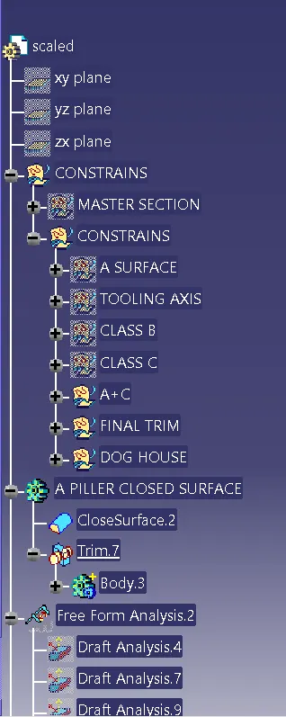
Tooling Axis Related tree structure 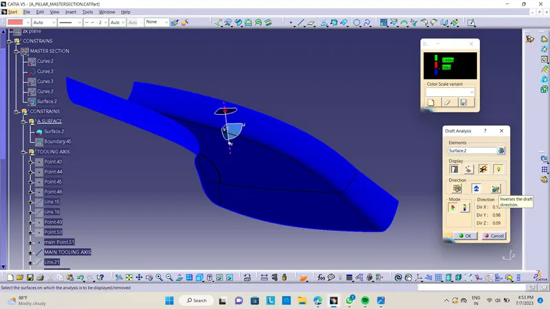
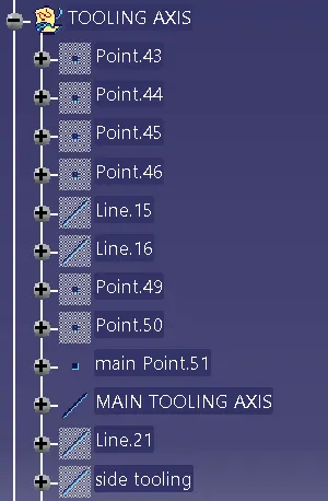
Draft analysis of a class A
PROCEDURE_2 :- Creation of the Class B surface.
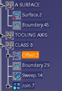
For creation the Class B surface we need to offset the Class A surface to the downward direction with the 2.5 mm .
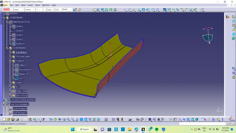
Offset of class A
After offseting we got a uncleared surface the large cut/ patched surfaces has got.
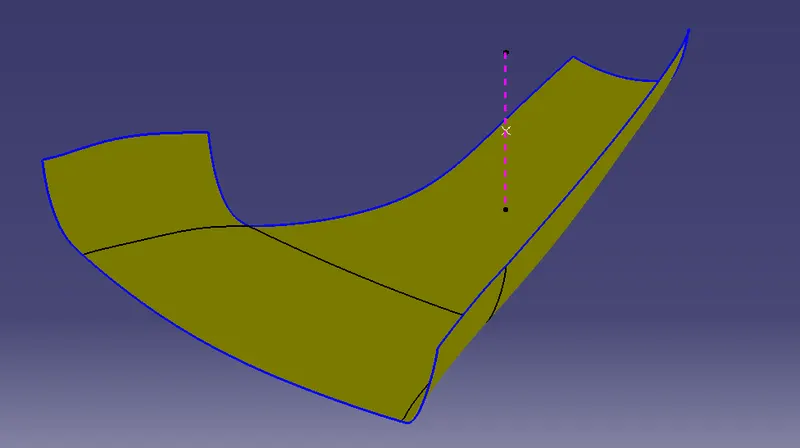
SNAP_8 :- Class B Patch area
so for the filling this patch / uncreared area we need to select a boundary with the adjecent corner of a offseted are & apply a sweep there.
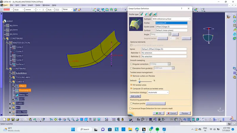
SNAP_9 :- Clear class B by applying sweep.
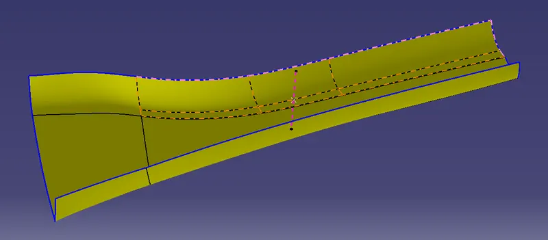
After that we need to select a join commond & select a offset & sweep together for getting a better class B surface.
SNAP_10 :- Modified Class B
PROCEDURE_3 :- Creation of Class C surface
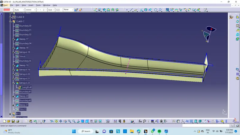
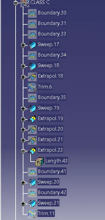
For the creation of Class C surface we need to take a multiple sweeps all over boundary line of the Class A
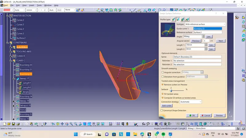
SNAP_11 :- Creation of Class C surface applying multiple sweep.
- In this procedure we need the Class A again to as a referance for creation the Class_C surface.
- Here 2 types of Sweeps are used for the making class_C surfaces.
- The 2 types as 1st is taking a referance surface with an angle of 90 Degree &
- 2nd is with the draft direction with the angle of 3 Degree. In the referance with surfaces we take a referance as a Class_A & in the with the draft direction as a Tooling axis as well.
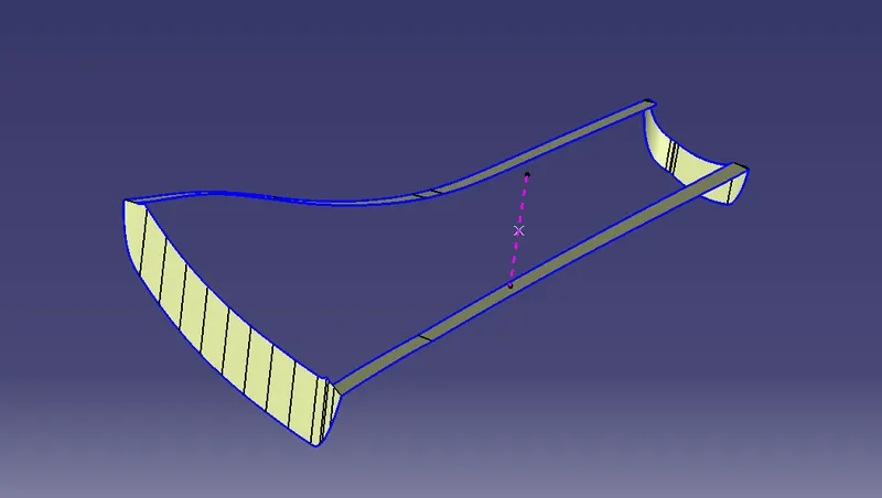
SNAP_12 :- Multiple sweeps of cass C surface
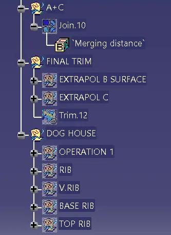
After the sweeps are applied there is need to trim the adjecent matting surfaces, so we need to extrapolate the proper extreme boundary line and apply the trim & finally join the trims together with an merging distance 0.003mm as well.
PROCEDURE_4 :- Final trim / Closed surface.
when we move on for getting the closed surface here we need to take a trim between the Class A + Class C or also we can join as well. After getting this trim we need to trim the Class B surface with the Class A+B . In this way we got a closed surface.
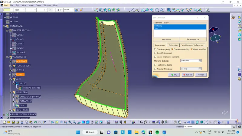
SNAP_14 :- Triming Class A with Class C
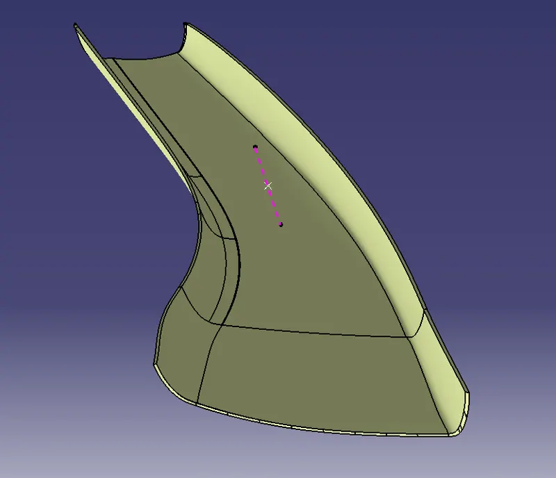
SNAP_16 :- Complete Closed surface
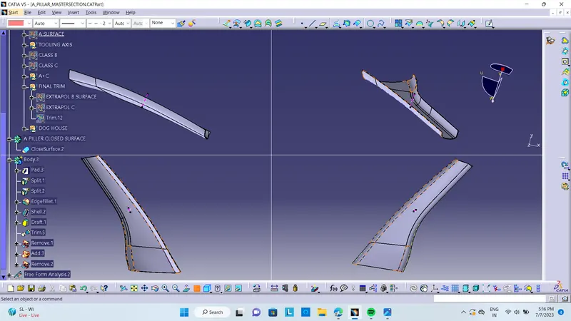
Draft Analysis of a closed body component.
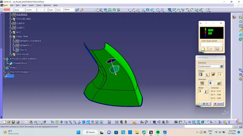
PROCEDURE_6 :- B_side feature creation.
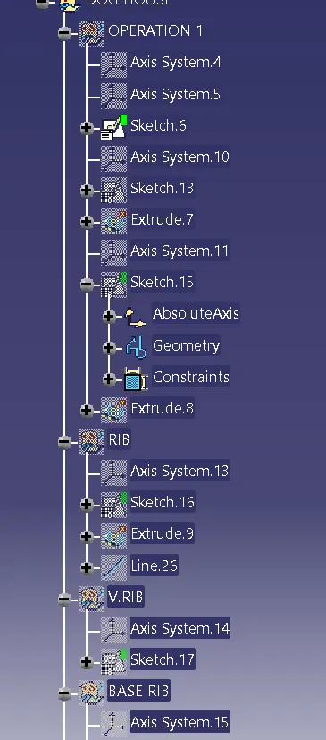
1] Dog house creation
We always create a B side feature or a attachement by using the help of master section & make a sketch properly guidence with the master section. First create a mid-point between the 2 point of a 2 lines of a master section followed by the dog house section. Finally created a iso-constrained sketch as well.
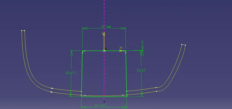
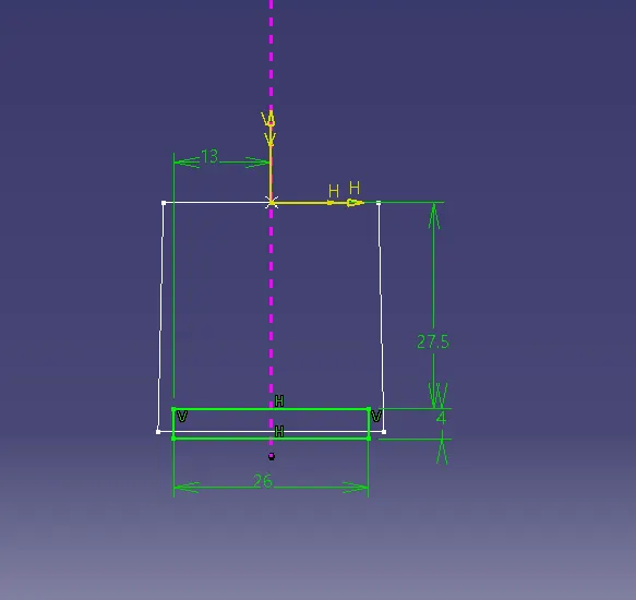
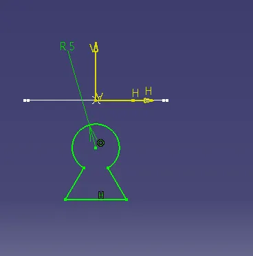
- After the sketches has make we need to pad or extrude it with proper thickeness has to be provided.
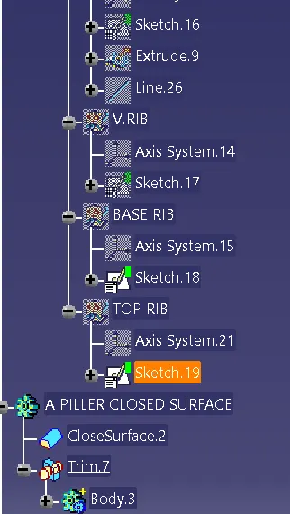
- In this way we have need to create the B-side feature dog-house inside sub elements of a Dog house as Plate,Ribs & pocket.
- The draft angle also has provided to inside the dog house is 0.5 with the referance of Tooling Axis & for the ribs & plate is 0.5 by the side core axis or lifter.
DOG HOUSE DRAFT ANALYSIS
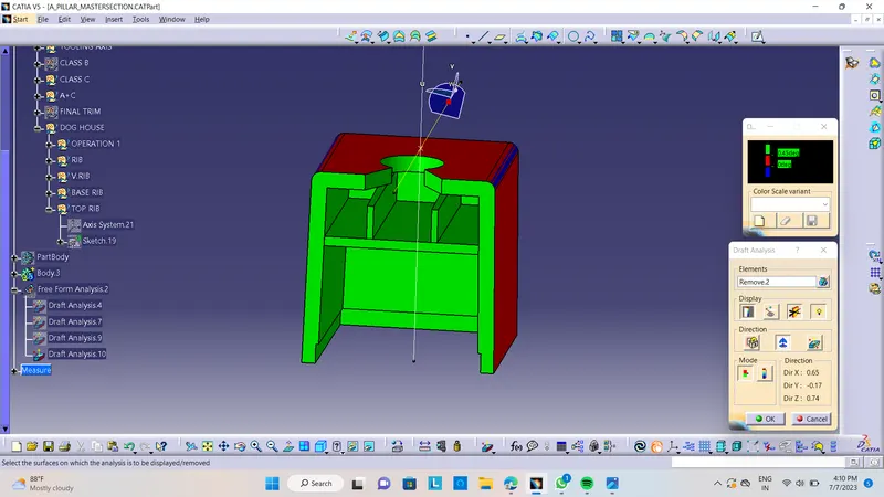
FINAL DRAFT ANALYSIS
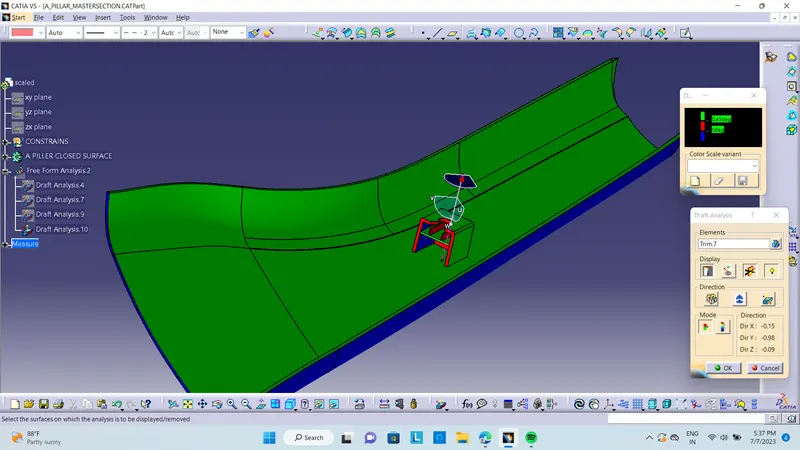
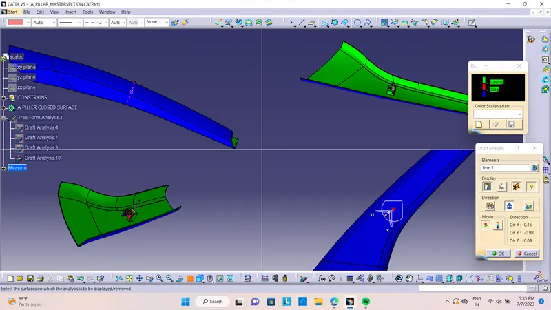
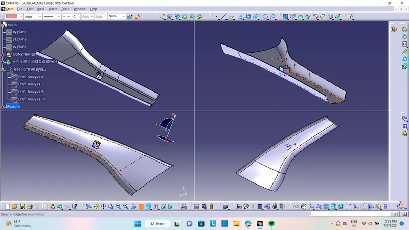
MASTER SECTION AND FINAL BODY
CONCLUSION :-
In this way we have cteated the closed body by the provided Class A surface. After this we have Created the B-side feature with the help of master sections as well. The required snaps are attached to the report & Explained each steps respectively. Finally Cat part file is also browse.
Thank You.