Week 11 - Project - A pillar Design with Master Section
AIM
To create A PILLAR with input master section and A surface given and to perform draft analysis.
INPUT GIVEN
- A Surface
- Master Section
- Part Thickness = 2.5mm
OBJECTIVES
- To create tooling axis.
- To create B and C surfaces.
- To perform draft analysis for A surface and the part body with the tooling axis.
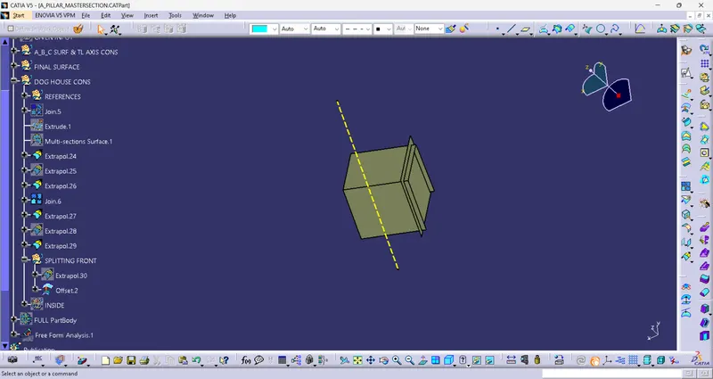
- To create dog house with reference of the master section.
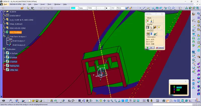
- To perform draft analysis of the part body with dog house with the main tooling axis and side core tooling axis.
A-PILLAR
In automotive design, the A-pillar refers to the vertical support structure on each side of the front windshield of a vehicle. These pillars are an integral part of the car's body structure and provide support to the roof, windshield, and sometimes the side windows.
The term "A-pillar" is derived from the alphabetical nomenclature used to categorize different pillars in a vehicle's body structure. The A-pillar is followed by the B-pillar, C-pillar, and so on. Each pillar plays a crucial role in maintaining the structural integrity of the vehicle.
The A-pillar not only provides support but also serves as a mounting point for various components, such as the side-view mirrors, weather stripping, and sometimes the front seat belt anchor points. Additionally, the A-pillar may house airbags or other safety systems to protect the occupants in the event of a collision.
Over the years, the design of A-pillars has evolved to accommodate various safety and regulatory requirements. Modern car designs often feature thicker A-pillars or utilize advanced materials to enhance occupant protection in the event of a rollover or side-impact collision. However, thicker pillars can sometimes obstruct visibility, so car manufacturers strive to strike a balance between structural strength and optimal visibility for the driver.
TOOLING AXIS
- Main Tooling Axis
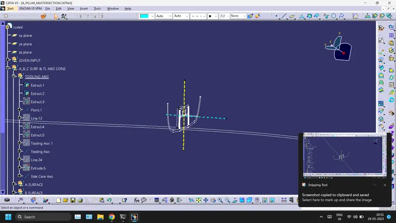
Tooling axis was created by bisecting line method taken from the reference of the master section.
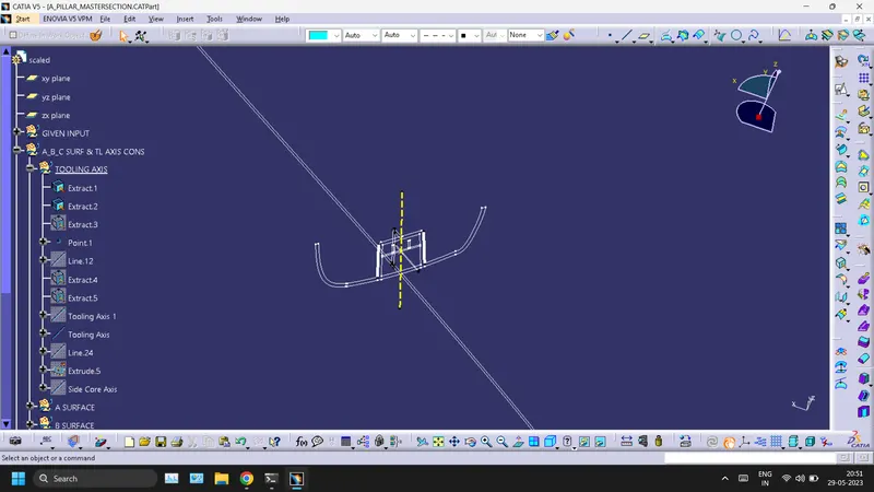
- Side Core Tooling Axis
It was created by the line perpendicular to the main tooling axis.
A SURFACE
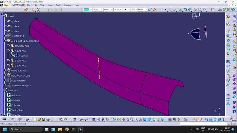
A surface provides aesthetic of the part.
B SURFACE
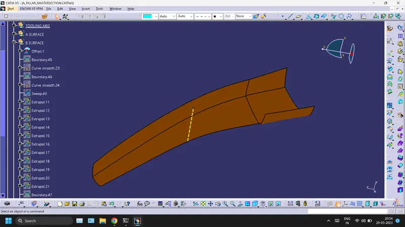
All engineering features like ribs, screw bosses, heat stakes, dog houses, locators, etc. are lie on the B side.
C SURFACE
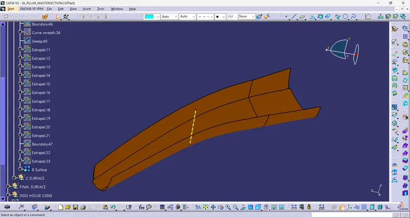
The surface that joins between the A and B surface is called C surface.
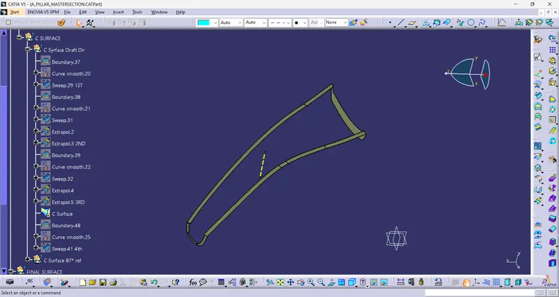
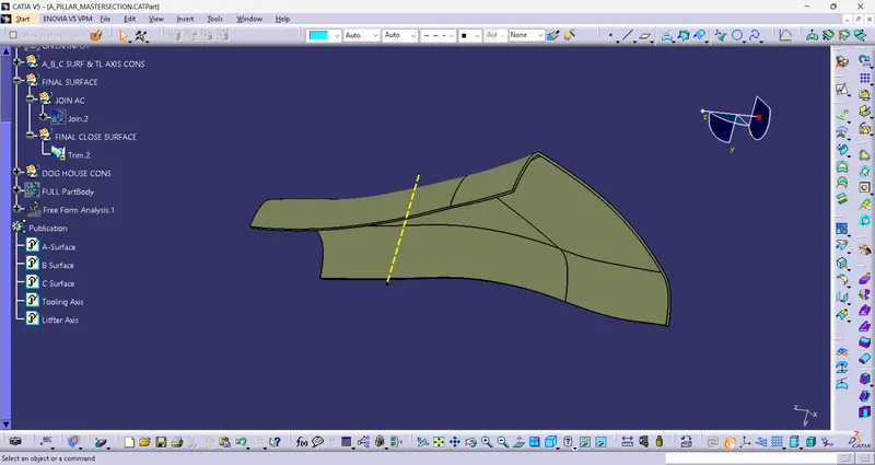
FINAL CLOSED SURFACE
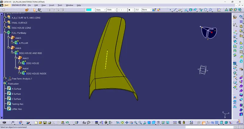
THICKENED PART BODY
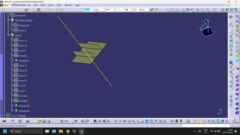
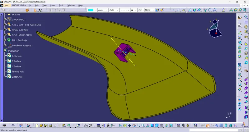
DOG HOUSE CREATION
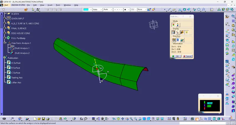
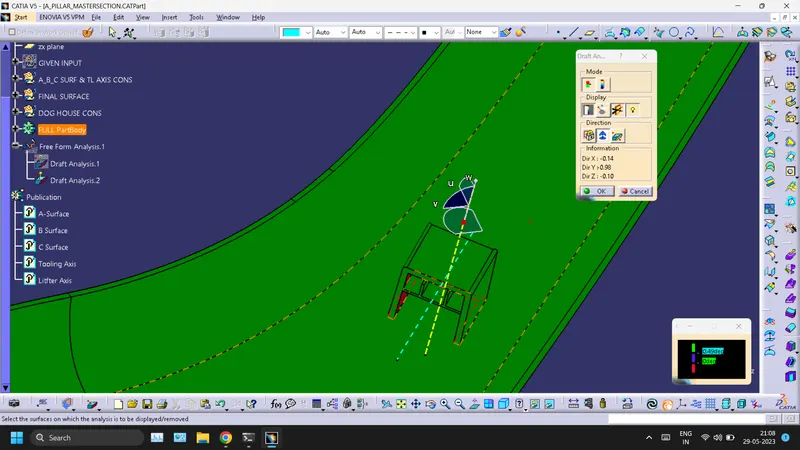
DRAFT ANALYSIS
- A SURFACE
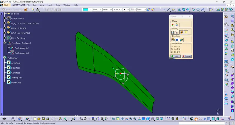
- FULL PART BODY