Week 11 - Project - A pillar Design with Master Section
DESIGN METHODOLOGY
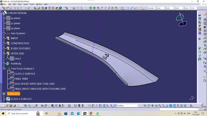
Class-A surface means visible surface. It gives the aesthetic of the component which is created by the styling team and gives to the part design engineer to create the part with all engineering aspects.
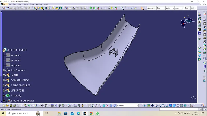
Given CLASS-A surface
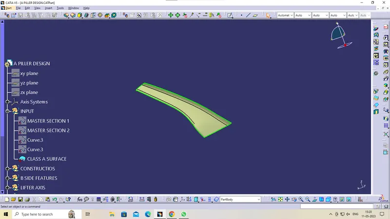
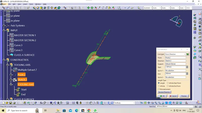
Procedure for TOOLING AXIS creation
- Check the best possible tooling direction by manually adjusting the compass.
- By analysing it is found that y axis as tooling direction would clear most of the faces without any difficulties.
- Now extract any surface and create a mid-point on it.
- Then create a dummy axis creating a line on the point and direction along the y axis.
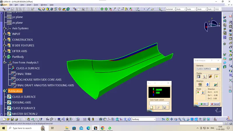
- Perform draft analysis to find whether the given axis clearing the draft analysis. If not create a new tooling axis.
CLASS B SURFACE
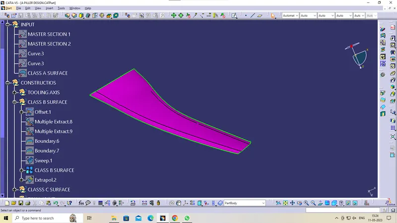
Class-B surface means thickness of a part it is not visible and is inside part. In other words, Class-B surface is a surface below a certain thickness from the class-A surface. This is the surface that contains engineering aspects of a model.
- Create offset surface of CLASS-A about 2.5mm inward direction.
- Check for the discontinuity and rework on the offset surface using extract, multi-extract, multi sections surface.
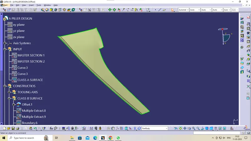
- Join the surfaces and ensure the final CLASS-B surface created has no gaps
CLASS-C SURFACE CREATION
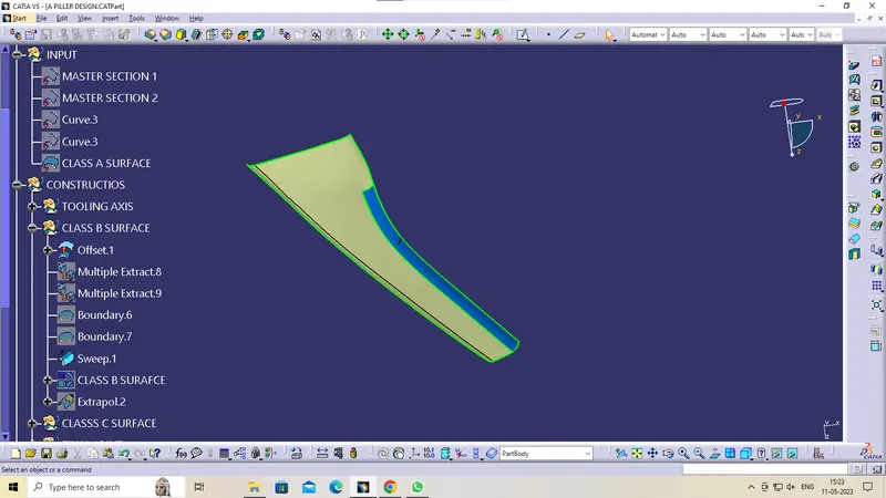
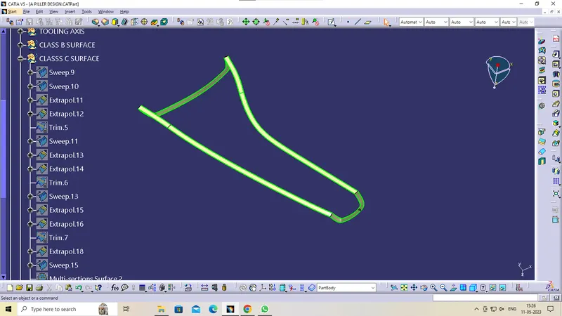
Surface that joins class-A and class-B surfaces is class-C surface. Class C is often specified for interior surfaces not readily visible, surfaces that will be covered by another part when assembled
- Create the sweep surfaces with reference to surface and tooling axis by multi extracting the CLASS-A boundary
- Join the sweep surfaces by using commands like extrapolate, trim, multi section surface.
- Finally join all the sweep surfaces and ensure the continuity of the CLASS-C surface.
CREATING THE FINAL JOINT
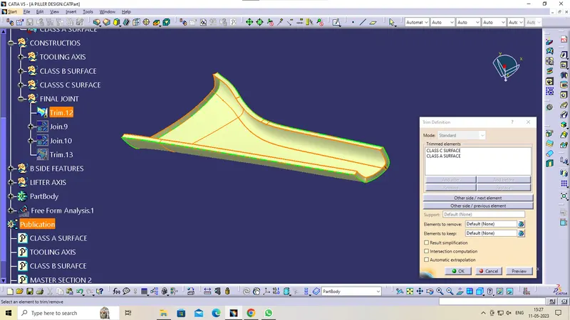
- For creating the Finals door trim surface, join the CLASS-A and CLASS-C surface together.
- Then Extrapolate the B surface little bit outward direction to make sure that there would not be any gap when trimming with joined surface.
- Then trim the extrapolated CLASS-B surface with Join surface (CLASS-A and CLASS-C)
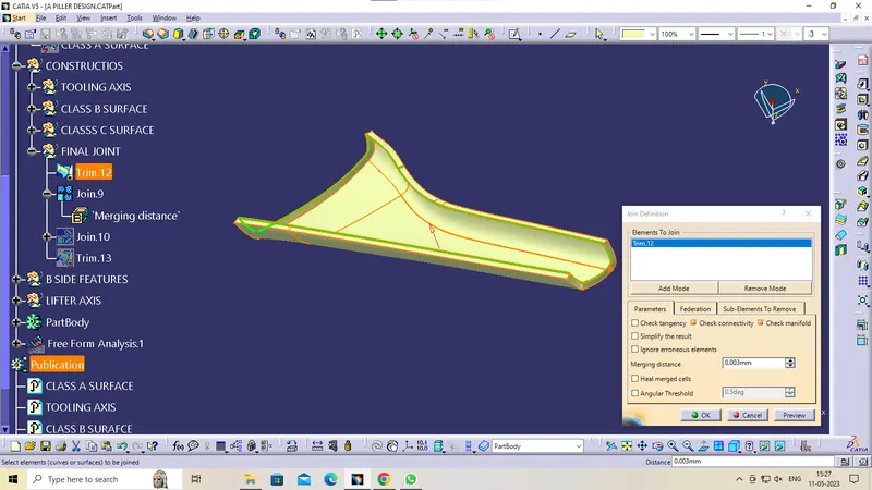
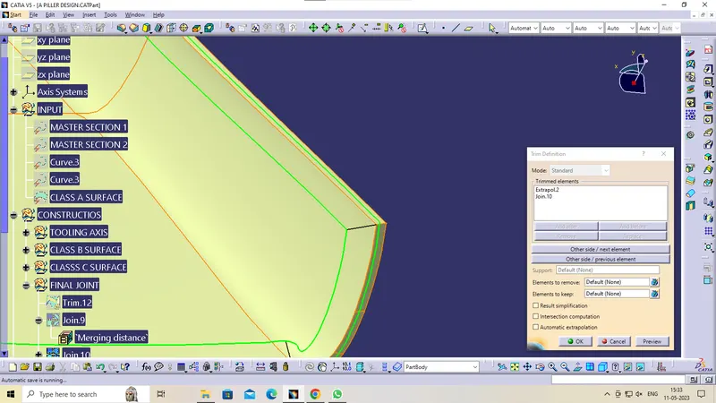
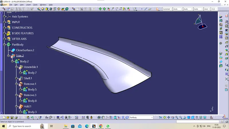
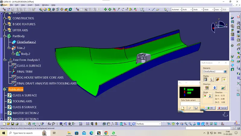
Make a solid part body using the close surface command in the part design workbench
DESIGNING OF THE DOG HOUSE
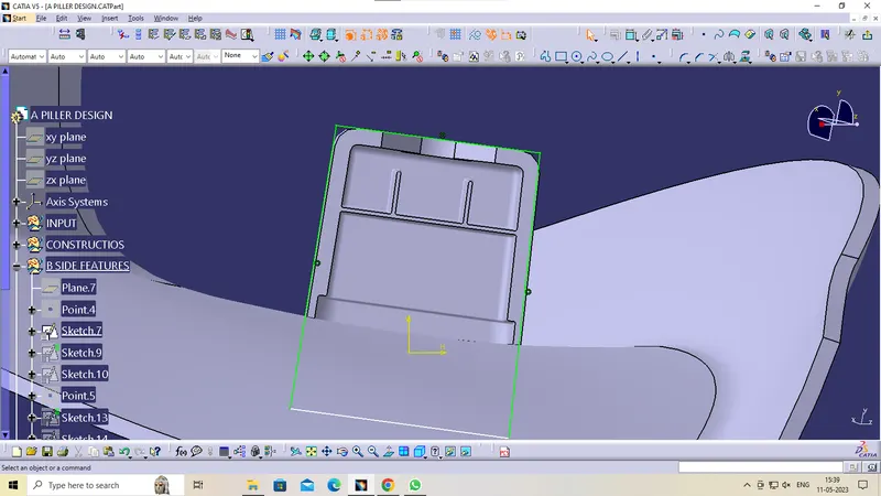
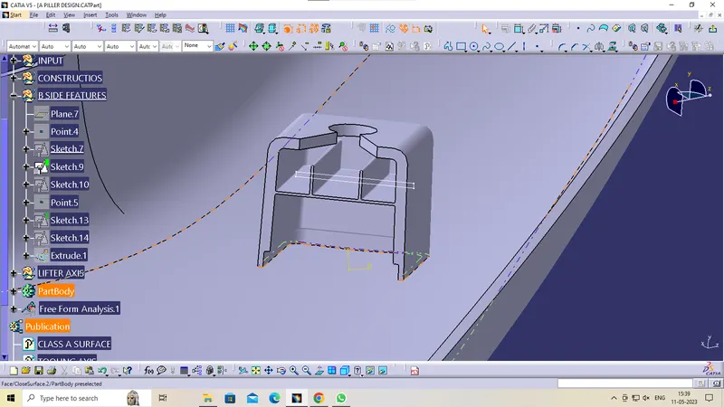
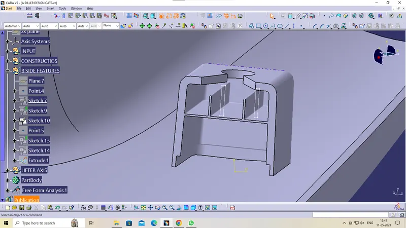
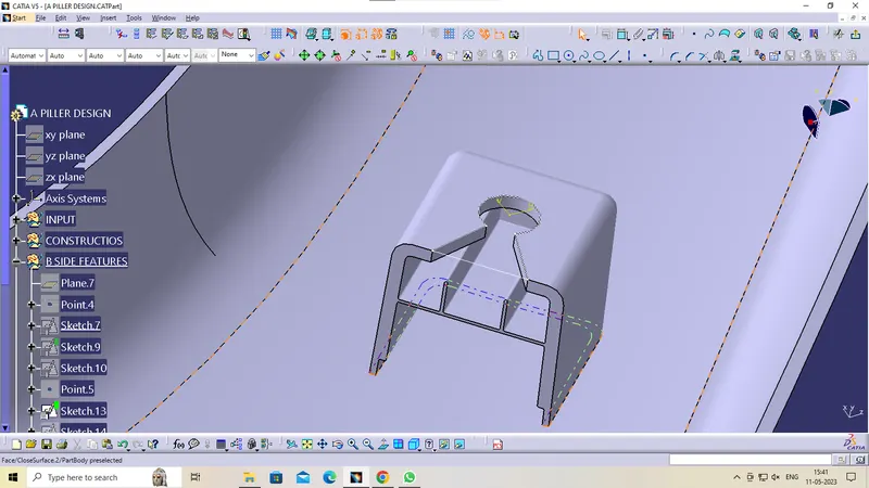
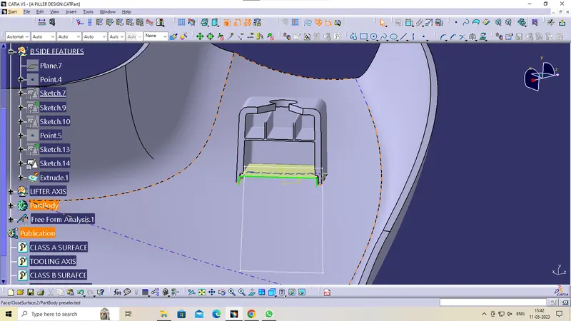
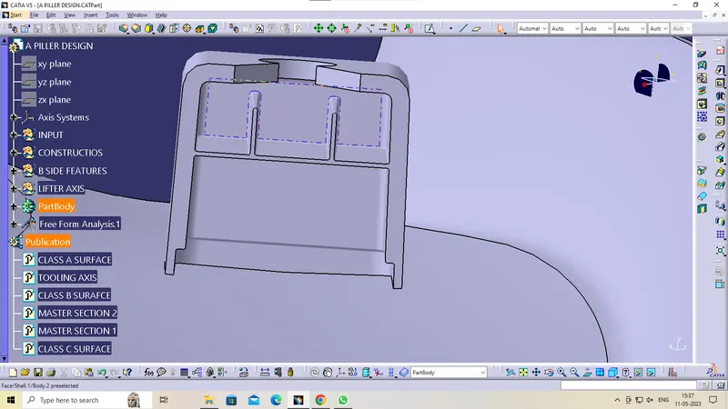
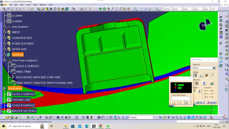
- The dog house is an engineering feature used in the plastic trim design. Dog houses are used as supporting features. Sometimes other engineering features like snaps; locators, etc. are mounded on them to increase their strength. The dog house is mostly used in automotive plastic and its main purpose is to help to avoid sink marks and saver of wall thickness
DRAFT ANALYSIS
Draft Analysis for the CLASS A SURFACE:
Draft Analysis for the Final Plastic body:
Draft Analysis for Final Component with Engineering Features:
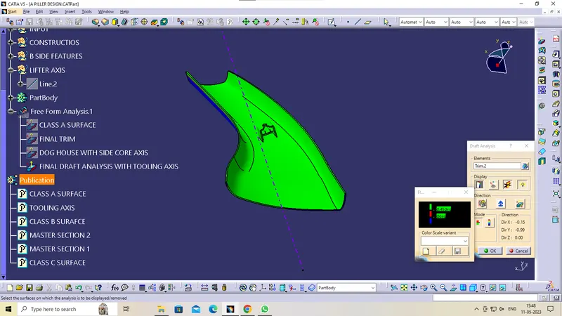
VARIOUS ORIENTATIONS OF THE FINAL COMPONENT
FRONT VIEW
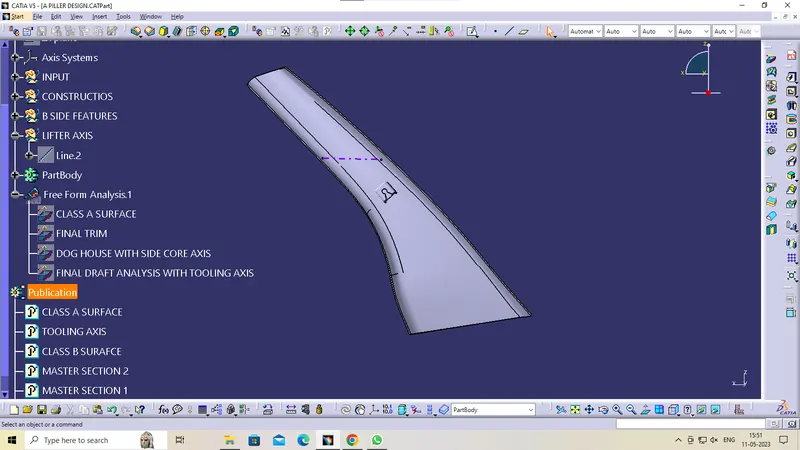
SIDE VIEW
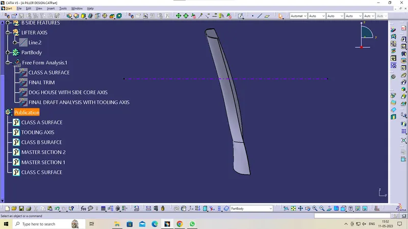
TOP VIEW
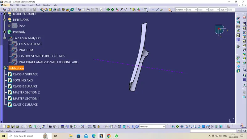
ISOMETRIC VIEW
CONCLUSION: Finally created A pillar Design with Master Section.