Week 11 - Project - A pillar Design with Master Section
Aim :
To create the A Pillar Design with the master section given as the intersection sketch with the Class A surface and create the tooling axis and perform the Draft analysis for the final solid part.
Objective :
- Create the required Tooling axis by using master section and bisecting methode.
- Design the Class-B and Class-C surfaces and close all three surfaces.
- Design the Dog house and its internal parts as given Drafts and mater section sketch.
- Draft analysis for the final solid part and side core Draft analysis.
Theory :
Tooling Axis :
Class-A surface is first analyzed to create the tooling axis or tooling direction that molds pull apart in injection molding. Tooling direction is important for plastic product design as it decides direction for mold seperation.
ROLE OF THE A-PILLAR:
A-Pillar is located on either side of your car’s front window (or windshield).
They also hold the hinges of your front doors. A-pillars are normally made of steel alloys.
Besides being a supporting member, A-pillars are very crucial as far as safety is concerned. A-pillars usually carry a significant amount of load during a frontal collision or a rollover crash. So the larger the width or cross-section, the greater would be the strength but A-pillars always block the driver’s vision (create blind spots) to some extent that can be realized while driving. So, having that said, using thicker A-pillars can make the situation even worst. It might further lower the driver’s vision and raise a question about the vehicle’s and passenger’s safety.
Hence, the design of A-pillars must be optimized giving equal importance to both strength and the driver’s vision.
Firstly, we have to create the required Tooling-Axis for the given Class A Surface while meeting the requirements of the necessary Draft Angle & then perform the Draft-Analysis Operation on the Class A Surface itself.
After that, we have to create the required Class B & Class C Surfaces using which we have to make the Final Plastic Component and perform Draft Analysis on it.
MAIN REPORT:
Types of Surfaces and their importance for an Automotive Plastic Designer:
- Class A Surface: Class A is an aesthetic surface with the highest quality finish. Most Class A Surfaces for an Automotive Component are made using 'Autodesk-Alias' based on the final Concept-Sketch. All Class A surfaces should have 'Curvature-Continuity', meaning the continuity between the surfaces should share the same boundary. It is taken as a reference by the Automotive Plastic Designer to create 'Class B' and 'Class C' Surfaces.
- Class B Surface: The Class B Surface resides below the Class A Surface at a certain thickness. It is created using Engineering Principles that consist of all the necessary features such as Ribs, Bosses, Snaps, etc. This surface isn't visible to the observer from the outside.
- Class C Surface: The Class C Surface is the surface created between the Class A and Class B surfaces to join them with each other.
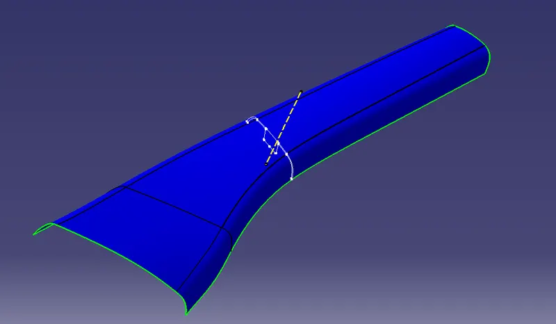
Now, we will begin by checking the State of Connectivity for the Class A Surface and ensure that there are no gaps between the surfaces as all the surfaces should be joined well together with each other and shouldn't consist of any discontinuities between them.
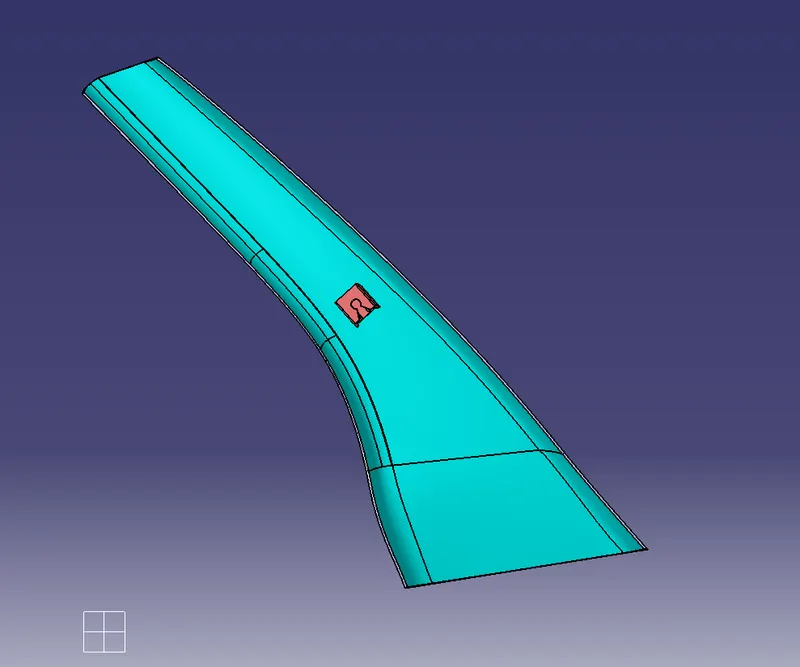
Our Class A Surface:
PROCEDURE TO CREATE THE MAIN TOOLING AXIS:
Since we have a Master Section provided to us using which we have to create the desired A-Pillar Plastic Component, We'll use that Master Section by extracting the lines as shown below and create a Bisecting Line with respect to those extracted lines to create our Main
TOOLING AXIS CREATION
- Tooling axis is the axis through which the mold opens, it is the first step before the design starts.
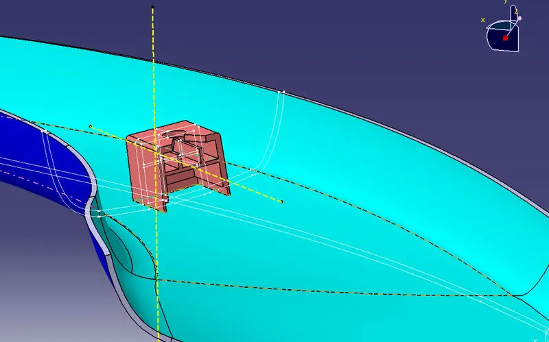
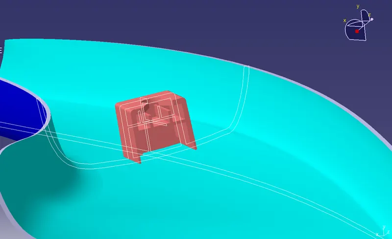
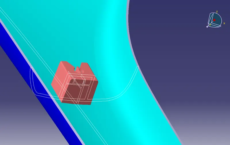
- In this project two tooling axis created one for the main part and other for the attachment feature dog house. The blue coloured tooling axis is the main tooling axis and pink coloured is the side core tooling axis.
- The main tooling axis is created by bisecting method , for the creation of tooling axis first two lines drawn through the master section by taking the vertex as reference through pont to point tool.
- After that a tooling axis is created by bisecting the two lines as shown in the fig below.
- The side core tooling axis created by taking a extract from the dog house and created a point in the middle of the extract and created a perpendicular line through that point.
DRAFT ANALYSIS ON THE CLASS A SURFACE:
Next, We will perform a Draft Analysis on the Class A Surface itself:
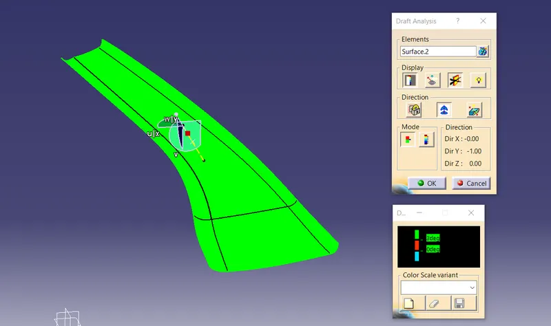
Before starting with a Draft Analysis Operation, we will go to the 'Customize View Parameters' option under the 'View Toolbar'. Then we will enter the 'Customize View Mode' where we will go under the 'Mesh' option and select 'Material' and press 'OK'.
To start the Draft Analysis in the 'Generative Surface Design Workbench', we will go to 'Insert' and then look for the option called 'Analysis'. Once found, we will go under that and click on 'Feature Draft Analysis. This will open the 'Draft Analysis' Dialogue box. There, we will ensure that under 'Mode' we have selected 'Quick Analysis', under 'Display' we will select 'Show or Hide the Color Scale' and then select '3 Degrees' as the permissible draft angle. Then, under 'Direction' we will choose the icon with the symbol of the compass on it which stands for 'Use the Compass to define the new current draft direction'.
Class B surface creation:
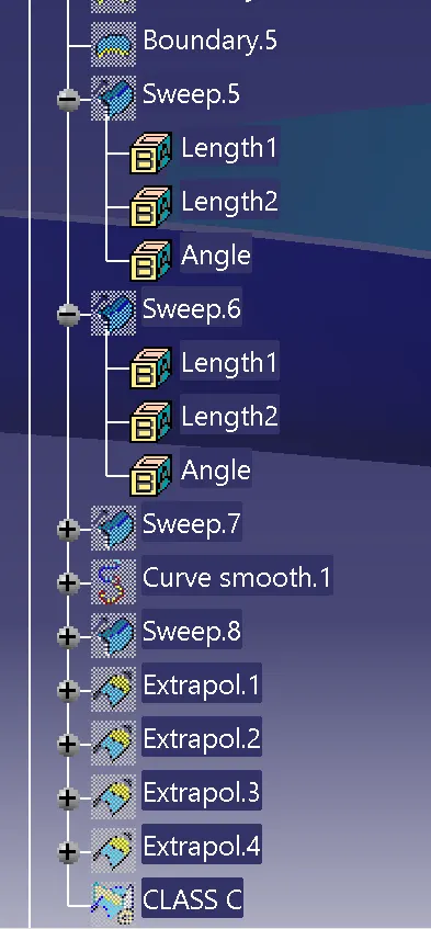
To create the class B surface initially, I measured the thickness of the master section (2.5mm). I offset the class A surface 2.5mm to the inside direction. The styling fillets on the class A surface are not offset properly, it created the patch on the offset surface. I used the sweep command to close the patch on the offset surface.
Class C surface creation:
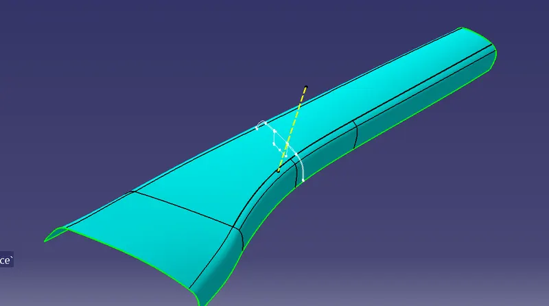
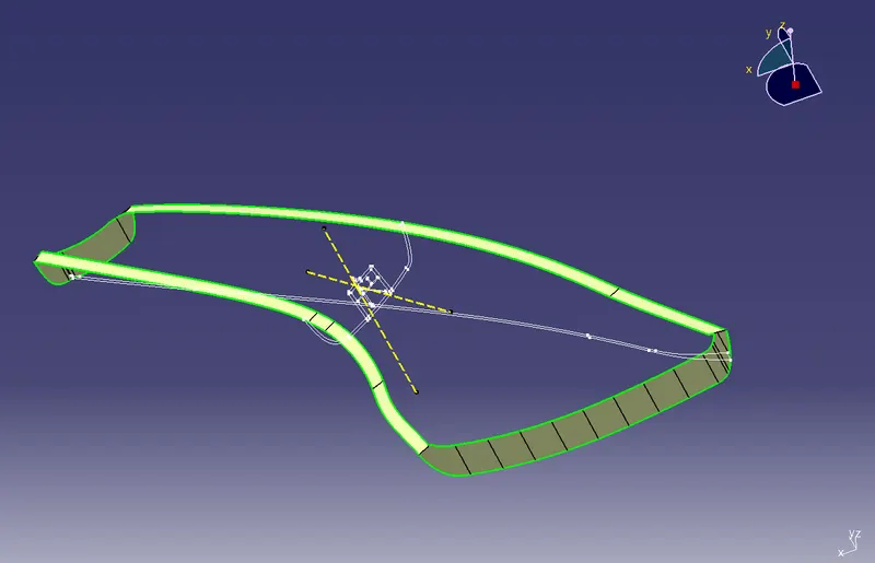
To order to create the class C surface, I used the sweep command. I sweep the class A surface edges along with referencing the surface for 4mm inside with 90deg. After the creation of the class C surface, the surface edges are needed to be extrapolated to intersect properly from all 4 sides. I trim the surfaces which extrapolated, to get the closed class C surface. I joined the class A surface and Class C surface to get a single surface of class A+C surfaces. I trim the Class B surface with class A+C surface join, to get the closed surface to create the solid body.
class C surface:
Solid part body creation:
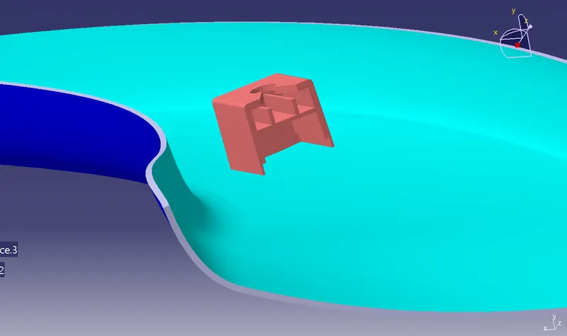
To create the solid part body, I used closed surface command in the part-workbench. I gave the closed surface as an input in the closed surface command.
solid body:
Dog House creation:
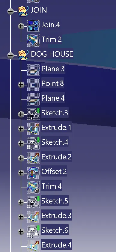
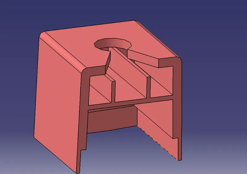
- To create the dog house on the B-side, I extracted the lines on the master section and I create a plane to extract the lines concerning the master section.
- I extracted the faces which are required to create the shell for the dog house, and I trim the surfaces with each other as per the master section dimensions.
Dog house outer shell:
- I created the side core access, by creating a line at the centre of the back surface by creating the point.
- I thicken the shell for mm to inside. After thickening the surface, I gave deg draft to inner surfaces of the dog house.
- Now we need to give the bottom cutout for the dog house. To give the bottom cutout, I extracted the surface and offset it to 1mm outside (the bottom cutout should be 40% of the thickness of the dog house). I extract the upper surface of the dog house and offset it to 17mm bottom direction, to trim with the offset of the inner surface.
- After trimming the bottom cutout surface, I split the surface from the solid shell of the dog house. I gave a 0.5deg draft angle to the bottom area concerning to the side core axis.
- I created the rib base and ribs concerning the master section dimensions, and I gave a 0.5deg draft angle to the rib base and ribs. After drafting the rib base, I added the rib base and ribs to the dog house shell to make a single body.
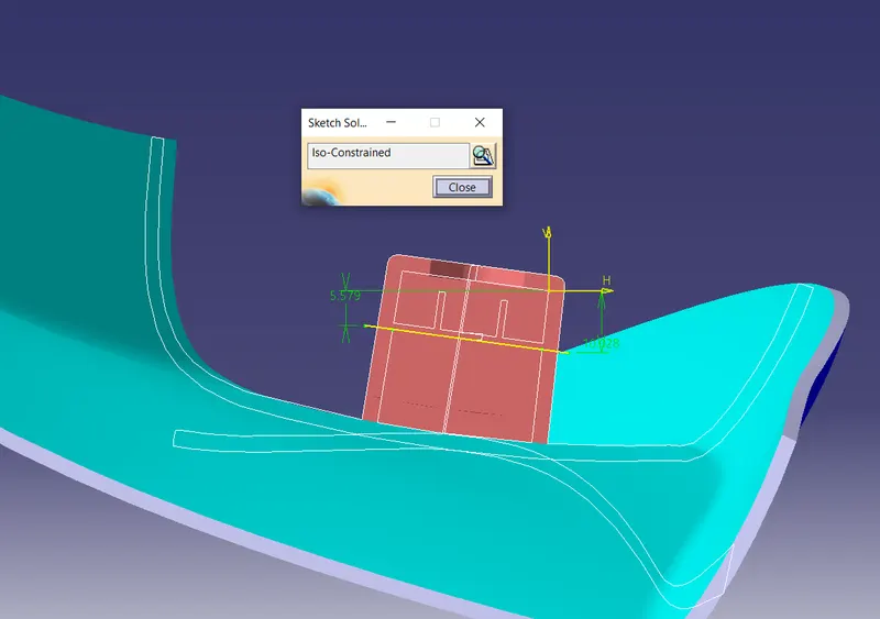
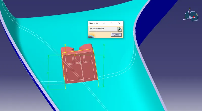
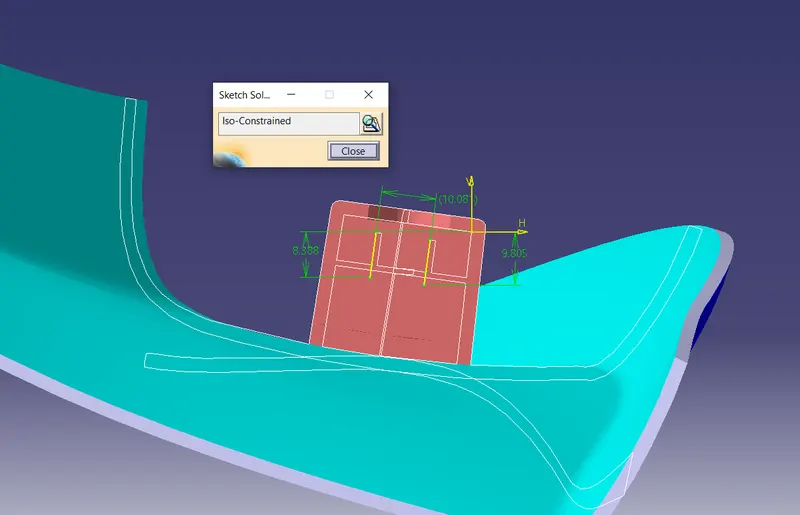
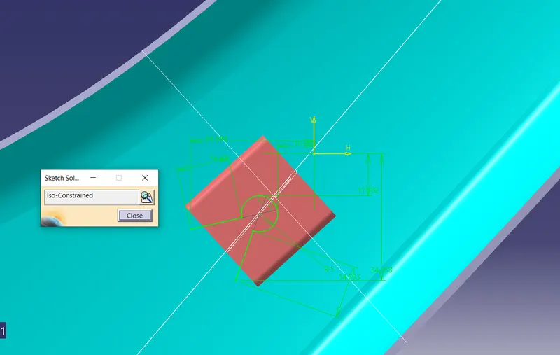
- I created a sketch for the top cutout on the dog house, and I pad the sketch to the downside and removed it from the dog house part body.
Dog house top cutout sketch:
Draft analysis for the solid part body:
The draft analysis is used to check the surface draft angel and to know whether all the surfaces are drafted properly or not.
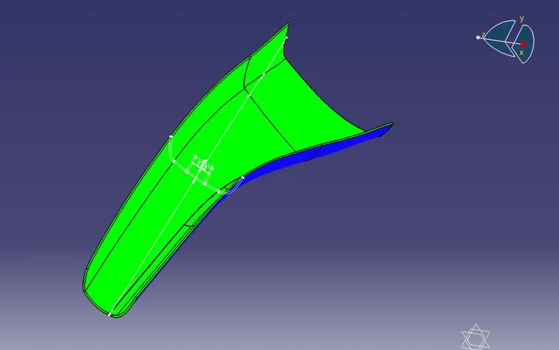
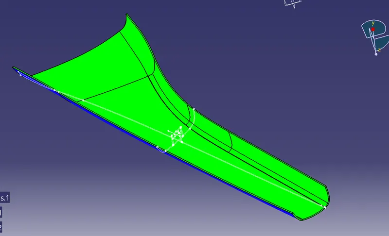
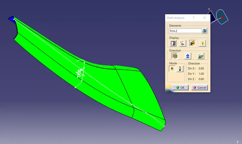
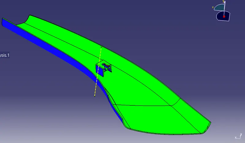
- The draft angle for the solid body of A pillar is 3deg, some surfaces are not cleared properly with a 3deg draft angle. Previously I mentioned in the class A draft analysis report with a 1.9deg draft angle all the surfaces are cleared properly.
- The draft angle for the outer surface of the dog house is 1.5deg.
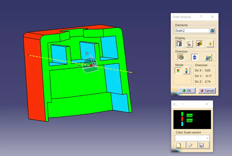
- The draft angle for the inner surface of the dog house is 0.5deg.
Draft analysis for A-pillar:
3deg draft angle:
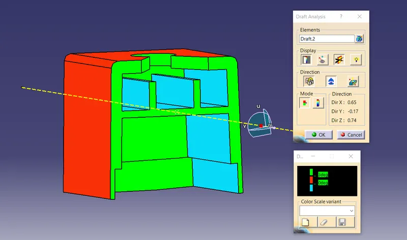
Draft analysis for the inner surface of the Dog house:
Green Colour stands for regions where the Draft Angle is more than 0.5 degrees,
Blue Colour stands for regions where the Draft Angle is between 0-0.5 degrees, &
Red Colour stands for regions where the Draft Angle is lower than 0 degrees
It is evident from the above images that the Draft Analysis is successful and the A-Pillar with the Doghouse is feasible to manufacture.
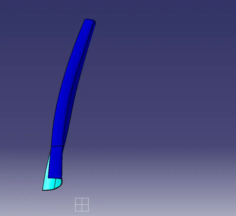
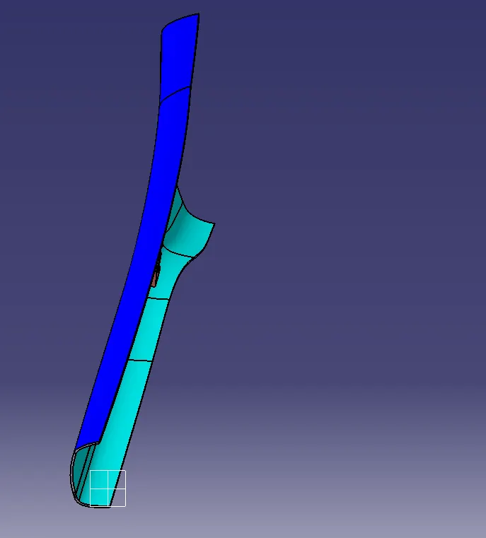
Different views:
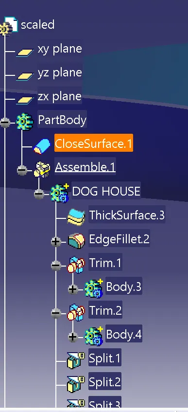
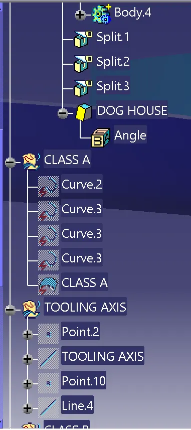
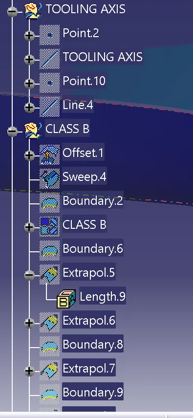
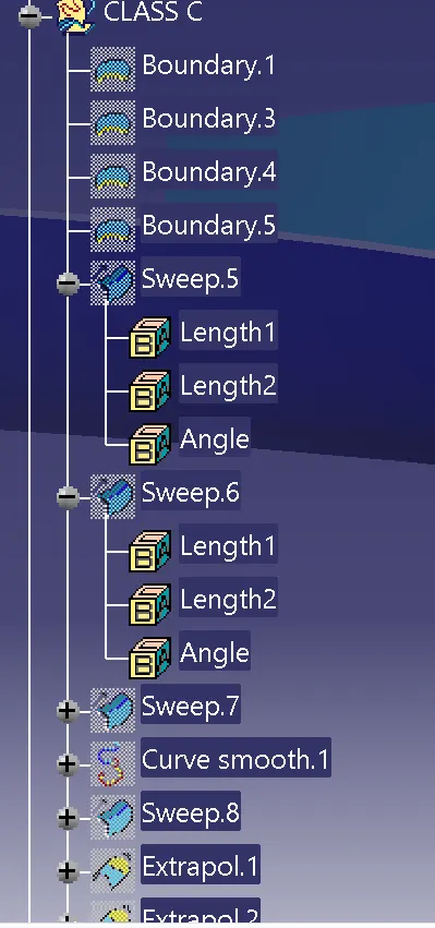
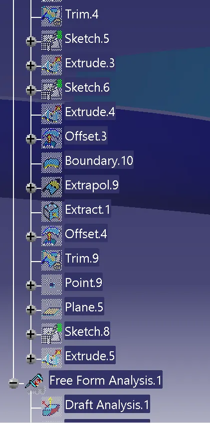
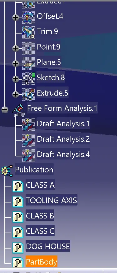
Tree Structure