Week 11: Project 2 - Emission characterization on a CAT3410 engine
1. Title – Emission characterization on a CAT3410 engine.
2. Objective –
- To import the CAD model of engine in converge Software and check for errors.
- To make sector for both omega piston and w piston, with make engine sector surface.
- To solve the case using suitable solver and convert the result for Paraview software.
- To import output files in Paraview and generate required contours and plots.
3. Introduction –
A heat engine is a device which transforms chemical energy of a fuel into thermal energy and uses it to produce work. Mainly, Heat engine is classified into two categories External combustion engine and internal combustion engine. when the products of combustion of air and fuel transfer heat to a second fluid which is the working fluid of the cycle, then engine is called external combustion engine and when the combustion of air and fuels take place inside the cylinder and are used as the direct motive force then engine is called as internal combustion engine.
Internal combustion engine can be classified further, according to the type of fuel like petrol engine, diesel engine and gas engine. Diesel engine works on diesel cycle which was proposed by Rudolf diesel in 1892. In Diesel engine, First, air is allowed into the cylinder and the piston compresses it—but much more than in a gasoline engine. In a gasoline engine, the fuel-air mixture is compressed to about a tenth of its original volume. But in a diesel engine, the air is compressed by anything from 14 to 25 times. Air will become hotter and injection of fuel results into explosion, which pushes piston, Simply, it generated mechanical energy. Diesel engines are up to twice as efficient as gasoline engines—around 40–45 percent efficient at best.
4. Theory
Simulating internal combustion (IC) engines is challenging due to the complexity of the geometry, spatially and temporally varying conditions, and complex combustion chemistry in the engine. Converge software provides special feature to simulate IC engine. in this study we are going to simulate emission characteristics of CAT 3410 engine.
One of the biggest advancements in piston technology is the use of different piston tops or crowns, the part that enters the combustion chamber and is subjected to combustion. While older piston tops were mostly flat, many now feature bowls on top that have different effects on the combustion process. The piston bowl is primarily used in diesel engine. Diesels don't have an ignition phase, so the piston crown itself may form the combustion chamber. The shape of the piston bowl controls the movement of air and fuel as the piston comes up for the compression stroke and it contributes to expel exhaust gases during exhaust stroke as well. So, piston shape can increase the combustion efficiency. In this study we are going with two different piston configuration one is omega and second is w. we will look how piston shape effects the heat rate, pressure, temperature by plot and we will look some animation as well.
5. Procedure –
IC engine is always going be tricky due its complex nature. To generate desire result it is very important to choose right physical model with a perfect solver. In these of simulation it is advisable to grab right initial conditions, boundary conditions, physical model etc. because it will take a lot of time to solve. In this study we simulated emission characteristic of CAT3410 engine, for it the procedure was as followed –
1. First, we imported the model and ran diagnosis tool to find errors. We found no errors.
2. We went with the creation of sector and considered close loop analysis. Piston body divided into sectors to save simulation time.
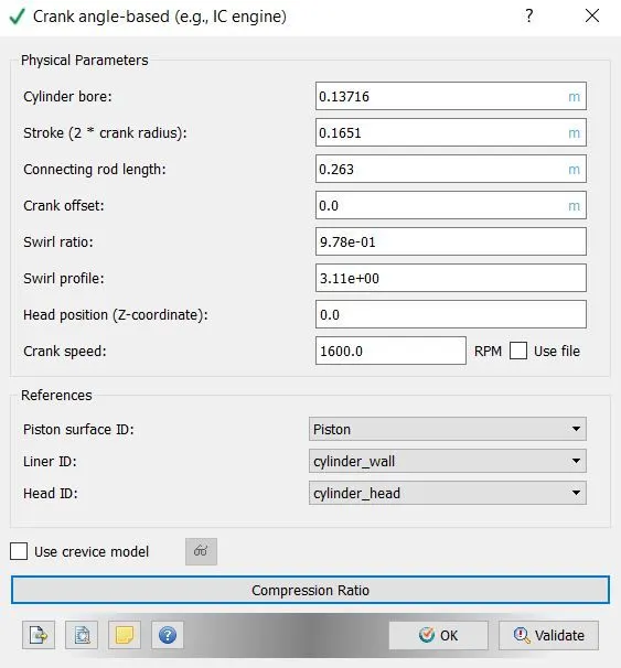
3. In the case setup we started with crank angles-based IC engine as application type. In crank angle-based menu some parameters were defined as shown in the following image.
4. In gas simulation parameter therm.dat file was imported which contains gas thermodynamic data specifically related to IC engine.
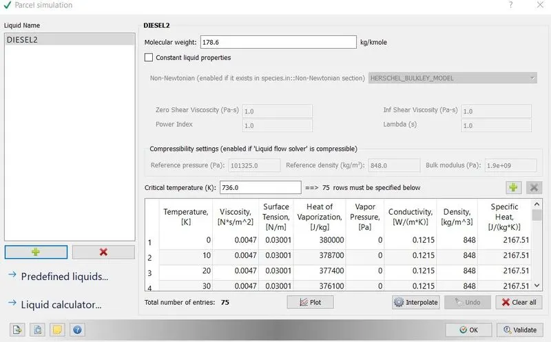
5. From the materials option parcel was enabled. In parcel simulation fuel Diesel2 was selected, which imported all the properties of fuel. Converge employs discrete Lagrangian parcels to simulate a special type of liquid in conjunction with spray modelling. In converge the Parcel simulation dialog box is for configuring properties of Lagrangian liquid parcels (such as for spray simulations).
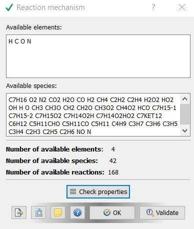
6. In reaction mechanism windows properties were checked to see the available species, which were imported by therm.dat file.
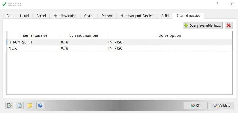
7. Diesel2 was defined in parcel option of species. SOOT and NOX were defined in internal passives.

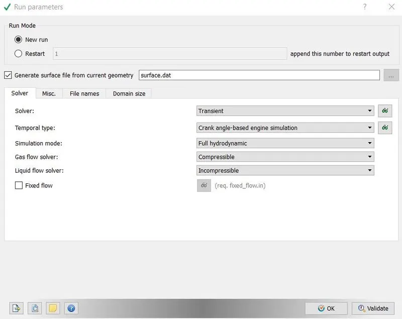
8. In run parameter transient was chosen as solver type with hydrodynamic simulation mode to simulate with the effect of liquid and gases. In temporal type crank angle-based engine simulation was chosen, because we wanted to run simulation on crank angles.
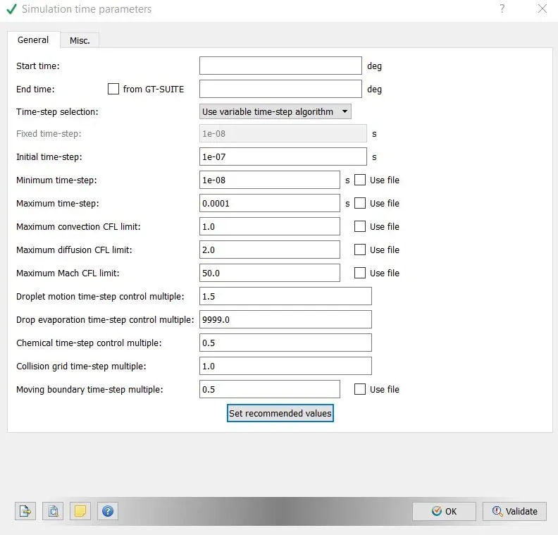
9. In simulation time parameter start and end time were specified in degrees, these were crank angles. Other parameters were defined as in the following image. Solver parameters were left as defaults.
10. There were 5 boundaries created in flagging process. Boundary conditions were given as the following images –
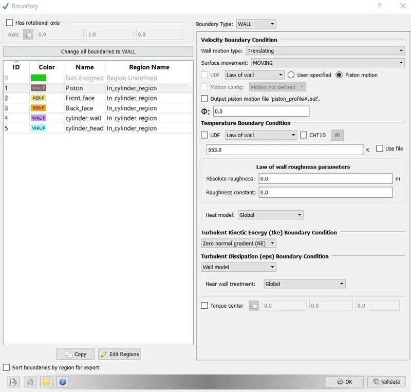
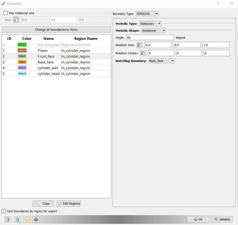
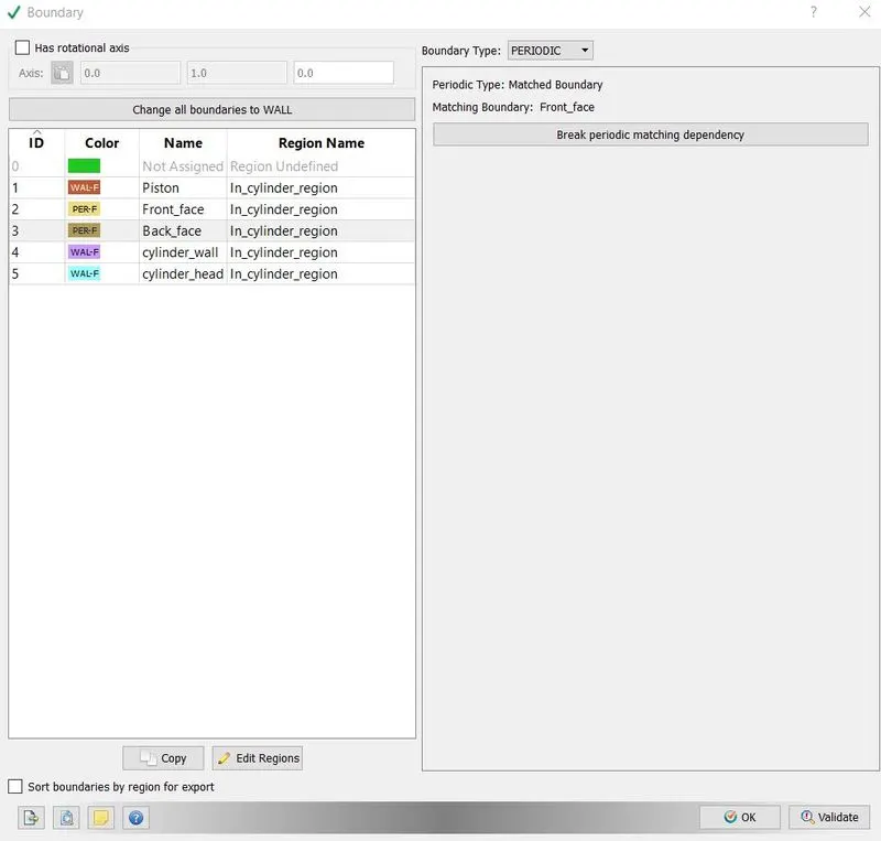
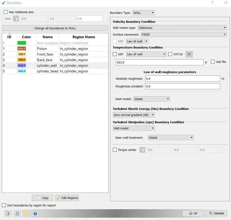
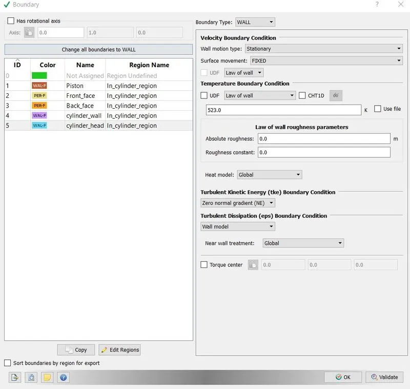
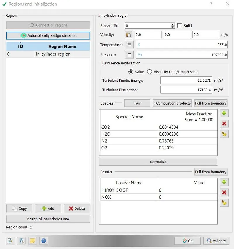
11. One region was defined, which was in cylinder. Since we were analysing emission characteristics of engine, so one region was enough. Species and their mass fraction were defined as follows.
12. From physical model’s menu spray and combustion with emission was enabled.
13. The Spray modelling dialog box is used to configure nozzles, injectors, boundary injections, injection rate-shapes, set various spray-related constants, and choose from several injection and drop models. We started with choosing drop evaporation option with frossling model, it determines how the radius of drop changes with time.
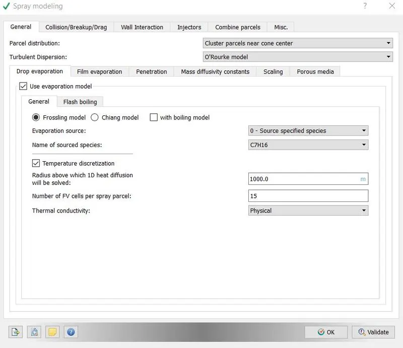
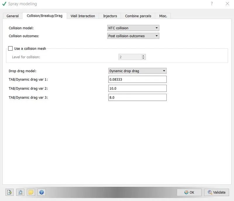
Converge contains the widely used O’Rourke and NTC collision models. These models are designed to estimate the number of droplet collisions and their outcomes in a relatively computationally efficient manner. We went with NTC model, since it is faster and more accurate than O’Rourke model.
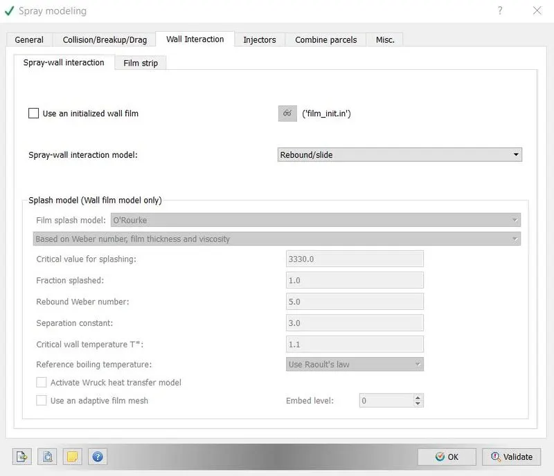
In wall interaction dialog box when define how liquid interacts with the walls and its parameter. wall film model is used for the modelling the interaction of liquid drops with solid surface and it comes with wall splashing option also. To determine the splash O’Rourke model is used and spray wall interaction wall film model was used.
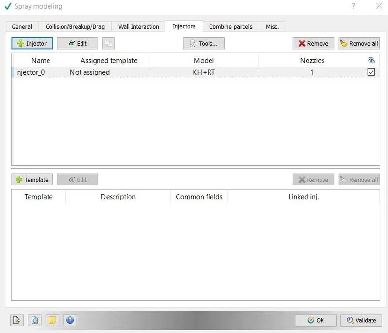
Converge offers two categories of liquid injection mechanisms: injectors and nozzles. An injector is a group of nozzles that have some of the same characteristics. Each injector can have any number of nozzles, each with its own hole size, cone angle, position, and orientation. We went with one nozzle with Kelvin-Helmholtz and Rayleigh-Taylor model. These models were responsible for prediction of liquid atomization and drop breakup. Time of injection, temperature, species and nozzle parameters were given as shown in following image.
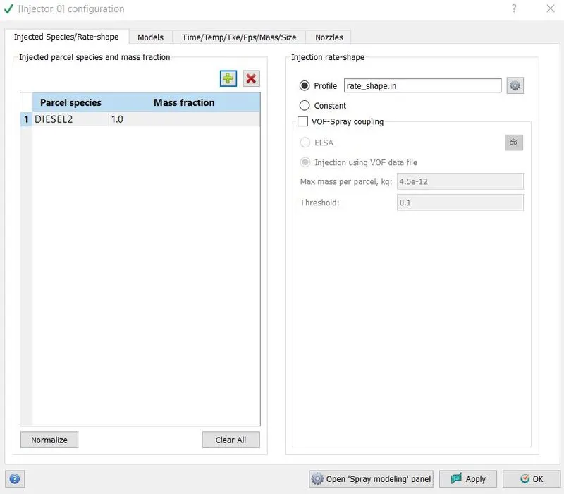
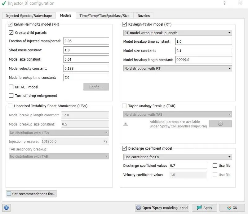
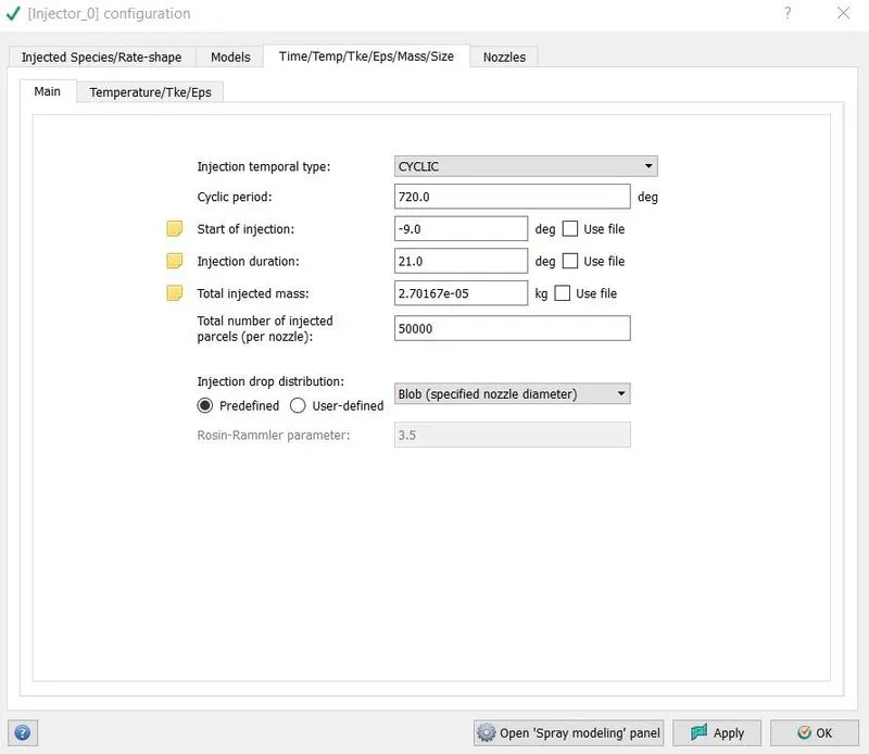
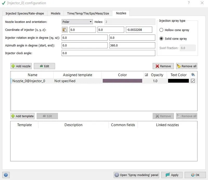
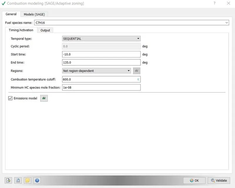
14. Combustion model in responsible for the chemical reactions and kinetics during combustion. We chose SAGE model, which solves for chemical reaction mechanism and its related parameters. In general setting, the time of combustion were defined in form of crank angles means combustion will take place between crank angle -10 to 135degrees.
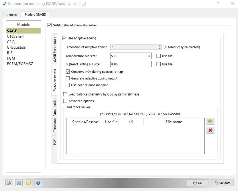
15. Converge provides many models to simulate NOx and SOOT production. Species of interest such as CO, CO2, and unburned hydrocarbons are always calculated or interpolated in CONVERGE, provided they are included in the reaction mechanism file and are a part of the combustion model used by the simulation.
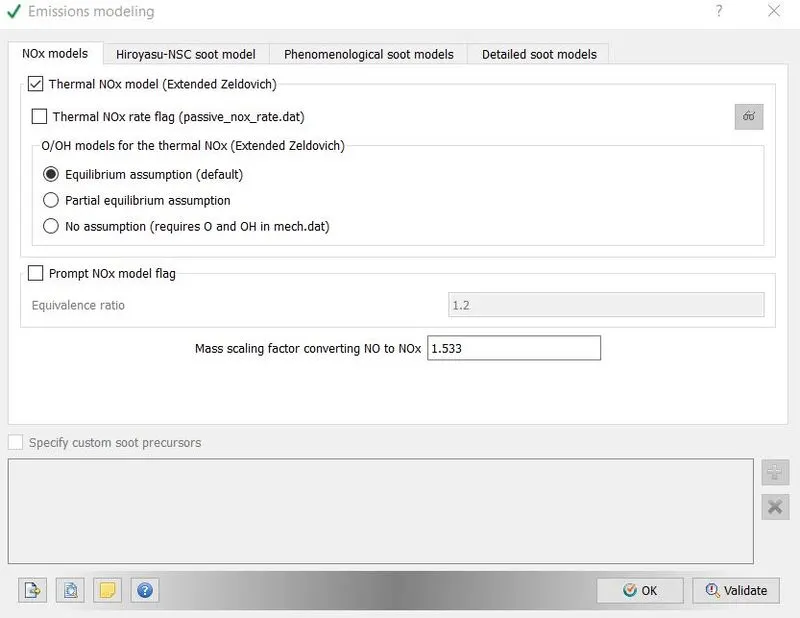
There are two NOx models one is thermal NOx and other one is prompt NOx. Prompt NOx model predicts formation of NO at low temperature fuel rich conditions and it is suitable for gas turbines. So, we chose thermal NOx model.
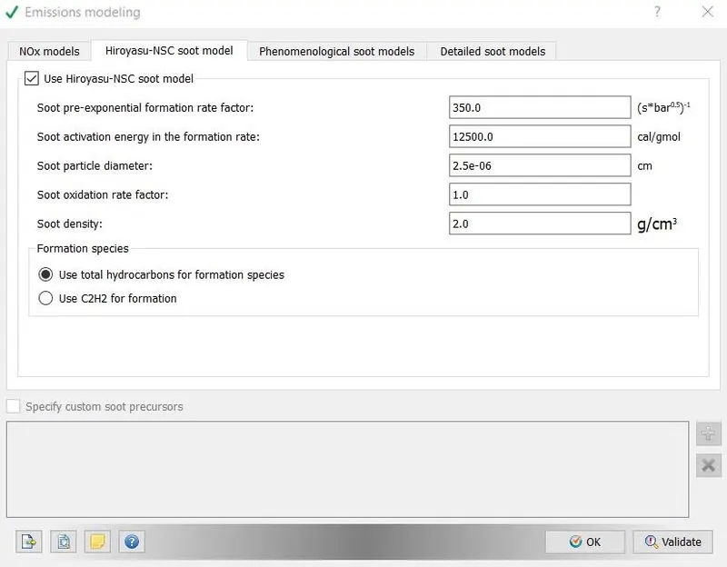
The soot models in converge describe the complex soot formation and oxidation process using several global steps, including soot inception, surface growth, coagulation, and oxidation. Phenomenological and detailed soot model are computationally expensive. So we went with empirical model.
16. We chose k-epsilon turbulent model and base grid was chosen as 0.004m, since we would enable fixed embedding and AMR the global grid size won’t be a big problem.

17. Adaptive mesh refinement option was enabled to get finer mesh. This option is very important because you cannot deploy same sized mesh on whole model. Velocity and temperature were two criteria which chosen for AMR. In velocity criteria sub grid criteria was 2m/s means above it, cell will be become finer by a factor of 2^n, here n is embedded level, in our case it is 2 and mesh will get finer by 4 times. Similarly, when sub grid temperature goes beyond 5K mesh will get finer by a factor of 4.
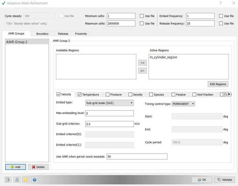
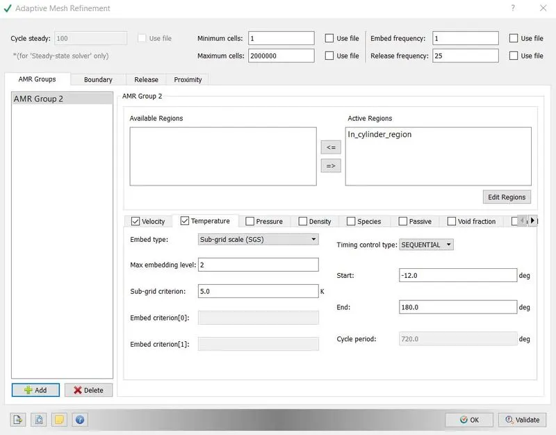
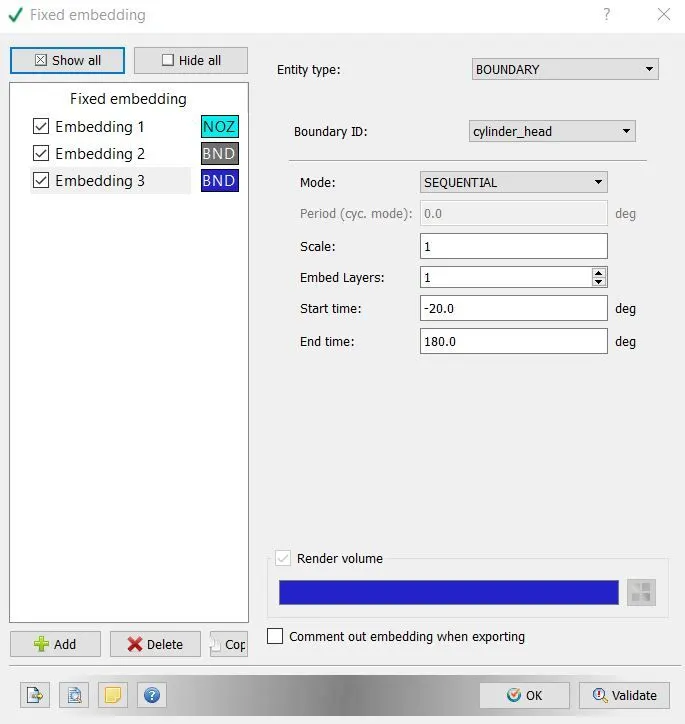
18. Fixed embedding option was enabled from grid control menu. Fixed embedding makes finer mesh of the basis of time or on the basis of crack angles. It is different from AMR because AMR option was dependent on the particular cell property. Fixed embedded was applied around nozzle, piston and around the boundary of cylinder. The parameter can be seen by following images.
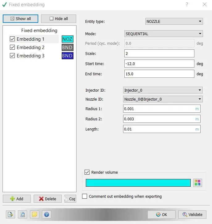
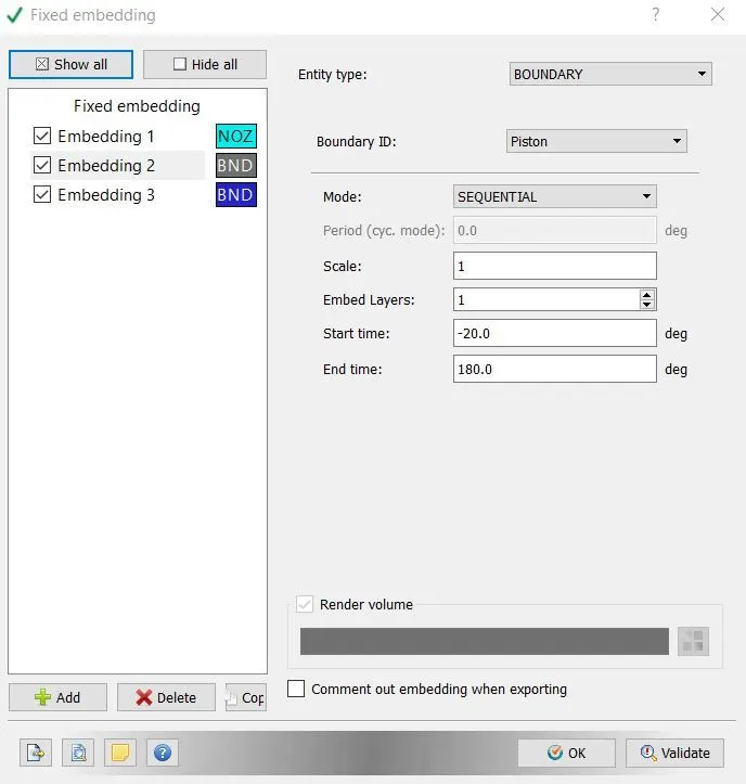
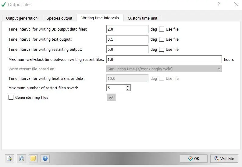
19. Time interval for writing 3D output data files was set to 2second for writing text output it was 0.1 second, other parameters of output files was left as default.
6. Results –
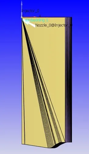
Geometry -
Omega piston -
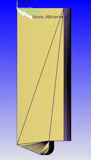
w piston -
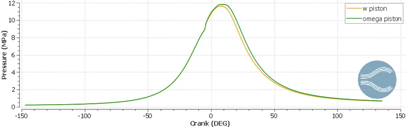
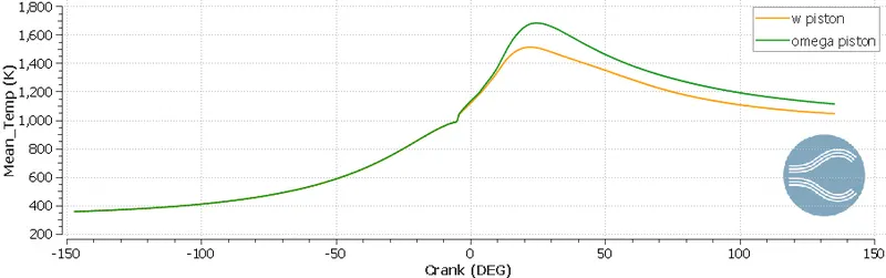
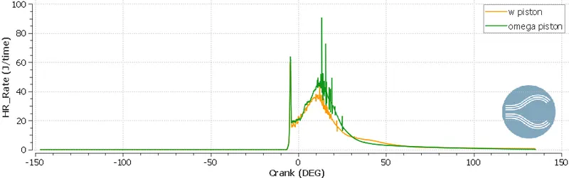
Useful plots and animations were generated to compare the piston profiles. Its very difficult to choose one of the them, because they have their own advantages. Animations were created to see spray wall interaction and piston movement.
1. We if look at the pressure plot, we can see we are getting higher pressure by omega piston, but we cannot declare it best only on this criteria.
2. Now, look at the mean temperature plot. For w piston mean temperature is low, we can assume there might be some fuel which is unburn, but we have to see further criteria to validate it. Low temperature gives us lower amount of NOx as well.
3. Now come to heat rate and integrated heat rate plots. Omega piston has higher heat release rate, that why it has higher temperature compared to omega piston. Integrated heat release rate is accumulation of heat released during whole cycle. IHR is higher for omega piston.
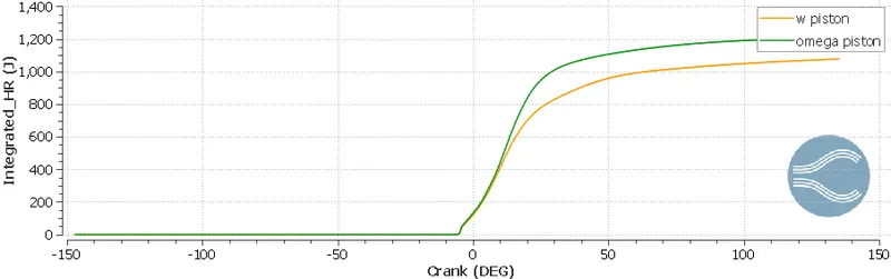
4. If we look the following plot, we can say omega piston has higher gases fuel, which is being burned lately, it can be verified from IHR plot also.
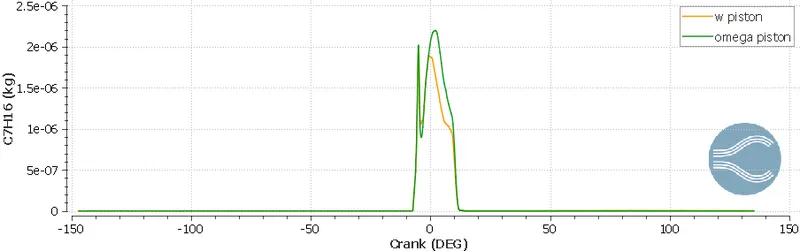
5. With omega piston there is lower NOx and it can be selected, if it someone targets lower NOx.
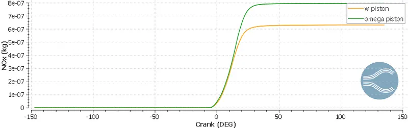
6. Open w piston has larger amount of carbon mono oxide, so we can say there is a lot of unburn fuel.
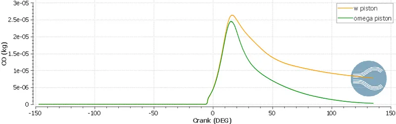
7. Omega piston produces lower soot, again, someone can choose it, if he is targeting lower Soot.
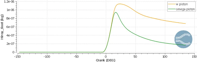
Bowl profile animation
Omega profile animation