Emission characterization on a CAT3410 engine
OBJECTIVE: To run the simulation of two type of piston bowl and characterize the emission and performance.
THEORY:
Diesel engine is widely used for non-road purposes, as well as transportation purposes because of its thermal efficiency, reliability and fuel economy. Diesel engine technology with higher efficiency and lower emission is still being developed. These developments up to now have led to an increase in the interest in the diesel engines for agriculture and maritime sectors where fuel economy is an important parameter. The numerical realization of a mathematical model for a physical system, in the form of a computer program, is shaped by a combination of practical and philosophical decisions which determine its ultimate form. A mathematical modeling of the internal combustion engine has been constructed and implemented as a computer program suitable for use on large digital computer system. The model strikes a balance between three competing factors: (1) the desire for physical realism, (2) the extent of experimental information on the physical processes occurring in the engine , and (3) the capabilities of today’s generation of computers. Modeling is a very useful approach for the development of internal combustion engine and optimization of its design parameters. Modeling of an internal combustion engine will develop as our understanding and knowledge of the physics and chemistry mechanism of the phenomena and as computers continue to increase their ability to solve complex equations. The models describe the thermodynamics, fluid flow, heat transfer, combustion and emission formation events of the engines.
Combustion has been a key technology for transportation since the last century. Despite its central role in improving living standards, it has had significant adverse environmental impacts. Notably, the CO2 emissions it produces have contributed greatly to global warming. In addition, combustion creates noise and produces pollutants that reduce air quality in urban areas. Consequently, legislature around the world are introducing increasingly strict regulations requiring the automotive sector to reduce its emissions. For instance, the European Union has implemented legislation limiting the fleet average CO2 emissions of vehicles to 130 g/km(depending on vehicle weight). Emissions of 130g CO2/km correspond to a fuel consumption of around 5.6 liters per 100 km (5.6l/100 km) of petrol or 4.9 l/100 km of diesel. This limit is expected to be reduced to 95 g/km in 2021 and then to between 68 and 78 g/km in 2025. Similar regulations have been or will be implemented in other countries. To meet these requirements, vehicle manufacturers are exploring a range of strategies to reduce emissions, including geometrical improvements, advanced combustion modes, turbo-charging, and variable valve timing. However, these techniques increase the complexity of vehicle engines and typically offer only marginal benefits.
The fuel used by IC engines also has major impact on our global environment. Burning of 1 kg of fuel consumes about 15 kg of air, and significant energy is required to pump it into and out of the engine. In addition, about 3kg of is generated, which contributes to the world’s annual production of 37 billion tons of , a major greenhouse gas (GHG). Some fear that GHGs can cause climate change with unpredictable consequences. To address this problem, the international Energy Agency’s roadmap is to reduce fuel use by 30-50% in new road vehicles worldwide by 2030, and in all vehicle by 2050. Although 2050 appears distant, the time required to bring new engines to production, together with the years needed for new technology to permeate the vehicle fleet, means that major effort will be required.
An alternative approach would be to replace emission-generating internal combustion engines with battery electric power-trains, which emit no harmful pollutants directly. This could be a viable solution if the electricity used to power the vehicles was generated from renewable sources. However, the capacity and working lifespan of currently available batteries are very limited, and the environmental friendly disposal of used batteries is challenging. Therefore, the complete replacement of internal combustion engines with battery electric power-trains is not currently a promising general solution to the environmental problems associated with transportation.
The grand challenge faced by engine and researchers over the next decades will be to devise technological advances that maximize the engine efficiency, minimize pollutant emissions, and optimize tolerance to a wide variety of fuels in power generation and transportation systems. Much recent engine research has focused on improving the understanding the ignition, which is highly dependent on the fuel’s chemical composition, and also on increasing the quality of the air-fuel mixture for improved combustion efficiency. Future legislation requirements for fuel consumption and emissions have prompted efforts to develop new engine technologies. This has resulted in extensive research on internal combustion engine systems because of their potential to
reduce fuel consumption and exhaust emissions. Two major factors controlling fuel/air mixing in ICE are the fuel injection system and the nozzle geometry. The present injection system needs to provide an improved spray characteristics such as spray penetration length, fuel atomization, droplet sizes and droplet size distribution to enhance a combustion system efficiency. Spray characteristics have a huge influence on the combustion system efficiency because the spray directly controls the dynamics of the combustion process. Spray dynamic are complex multi-scale physical phenomena that are highly sensitive to the injector nozzle geometry(cavitation), nozzle exit conditions(turbulence), and fuel injection pressure. These conditions can change the atomization behavior and course of physical processes of the spray after the nozzle exit. The measurement techniques have some limitations to incorporate all the physical processes. Also, it is very challenging to isolate all the physical processes. On the other hand, Computational fluid dynamics (CFD) simulations offer an alternative way of studying these processes, and are becoming an increasingly reliable and effective tools for studying phenomena such as spray injection and its subsequent development. On the other hand, the simulation techniques are becoming an increasingly reliable and effective tool for the detailed study of insight phenomena including spray injection and its subsequent processes. However, due to different scales are involved to address the atomization and nozzle flow, it is challenging the entire phenomenon (atomization and nozzle flow) in the single CFD frame work.
At present, direct numerical simulations (DNS) is the only computational method capable of resolving all length scales involved in the atomization processes [5]. Unfortunately, its high computational cost largely restricts its use to academic test cases. An alternative method with lesser computational costs, the large-eddy simulation (LES) technique, has been widely used to simulate unsteady multiphase phenomena. LES can accurately capture intrinsically time- and space-dependent phenomena because it directly resolves large-scale turbulent structures and uses a model to describe sub-grid scale structures.
Spray modeling
Spray models are very important in engine CFD simulations because they influence the subsequent mixing, ignition, combustion and emission predictions. Spray models include those describing the flows inside injector nozzles, atomization of the continuous liquid after the fuel leaves the injector nozzle (primary breakup model), breakup of the formed liquid drops (secondary breakup model), momentum exchange between the liquid and gas phases (i.e., the drag force that liquid droplets experience and the deformation of the droplets), collision between liquid drops and its possible outcomes (collision model), interaction between sprays and walls (e.g., wall-film model), and evaporation of the liquid fuel (evaporation model).
Spray sub-models
Various sub-models were implemented to account for the effects of turbulence , coalescence , evaporation , and droplet breakup in the fuel spray simulation.
Discrete phase modeling
Fluent provides a model that is especially for spray simulations, or more general suspended particle trajectory simulations. This is the Discrete Phase Model (DPM) and it is based on the so-called Euler-Lagrange method. In the computational domain there are two separate phases present, namely, the continuous and the discrete phase (particles). The transport equations are solved for the continuous phase only and the motion of particles is dealt with particle trajectory calculations. Through an iterative solution procedure, the mass, momentum and energy interaction between both phases can be realized.
Combustion Modeling
Various combustion models have been developed to simulate a wide variety of combustion phenomena in both spark-ignited (SI) and compression (CI) engines, including spark and auto ignition, laminar and turbulent combustion, premixed, non-premixed and stratified-charge combustion, kinetics and mixing-controlled combustion, and flame propagation combustion. For CI engines, combustion modeling also must resolve two steps: low-temperature chemistry which leads to auto ignition, and the following high-temperature reactions which contribute most of the heat release.
Since combustion in DI engines is turbulent and many turbulent combustion models with different levels of complexity have been proposed for engines applications, including models based on RANS and LES turbulence models. However, since RANS models, specifically the k- model and its variants, are the most commonly used turbulence models at present. In general, there are two ways to describe the combustion process in engine cylinders. One is to use a combustion sub-model to describe the overall combustion characteristics (i.e., flame propagation, reaction rates, and so on) of a combustion process. Combustion models such as mixing-controlled combustion models, flamelet models, and probability density function (PDF) models belong to this category. The other way is to use a detailed reaction mechanism which describes the complex reaction pathways and reaction rates of the important chemical reactions involved in the combustion process and solve for the rate of change of each species in the mechanism.
Before describing the models, two variables which are used in these models are introduced. The first is the mixture fraction (Z) and the second is the reaction progress variable (c). The mixture fraction quantifies the local mass fraction of materials that originate from the reactant fuel. It is mostly used in the analysis and modeling of non-premixed reacting systems. For premixed combustion systems, a reaction progress variable is used. The progress variable increases from zero in the unburned reactants to unity in the burned products. The calculation of the progress variable can be associated with either the mass fraction of a specific species (combustion products) or temperature.
CONVERGE offers two different methods for modeling the ignition and combustion processes. The first method uses separate models for ignition and combustion. These models
are based on the Shell ignition model and the Characteristic Time Combustion model, and this method is relatively computationally inexpensive. The second approach, described in the SAGE detailed chemical kinetics solver section, considers much of the chemistry taking place in combustion applications. Although the runtime using detailed chemistry can be significantly longer than with the first approach, the accuracy of the simulation may be greatly enhanced with the inclusion of detailed chemistry. Nonetheless, there is still often a need for the rapid turnaround time that can be achieved when the simpler models are used.
CONVERGE contains the SAGE detailed chemical kinetics solver which models detailed chemical kinetics via a set of CHEMKIN-formatted input files. To solve the systems of ordinary differential equations (ODEs), SAGE uses the CVODE solver, which is part of the SUNDIALS (SUite of Nonlinear and DIfferential/ALgebraic equation Solvers) package.
A chemical reaction mechanism is a set of elementary reactions that describe an overall chemical reaction. The combustion of different fuels can be modeled by changing the mechanism (e.g., there are mechanisms for isooctane, gasoline, n-heptane, natural gas, etc.). SAGE calculates the reaction rates for each elementary reaction while the CFD solver solves the transport equations. Given an accurate mechanism, SAGE (in addition to AMR) can be used for modeling many combustion regimes (ignition, premixed, mixing-controlled). You can use SAGE to model either constant-volume or constant-pressure combustion. Note that SAGE consistently uses CGS units for all calculations.
PROCEDURE:
To make the sector surface we need the geometry file. By using the "Make engine sector surface" tool we can create a surface file.To extract the sector files, upload the surface file in the below-shown dialog box and click on extract.A set of files are generated in the directory, Next, open the same toolbox to extract the geometry. Enter the dimensions of the Bore, Stroke, and Connecting Rod. These values are provided in the forum.Check the use bowl profile, the compression ratio value is known it is 17.5. The sector angle is set to 60 degrees with one nozzle in it.After checking the "use bowl profile" option the bowl profile dialog box activates, import the bowl profile file using the import option situated within the bowl profile box, and click on extract to create sector surface.
By using the above mentioned process, we have developed both open-w and omega pistons.
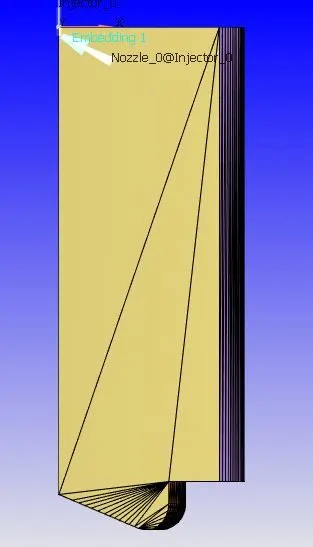
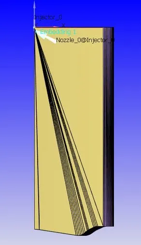
After this we setup crank angle based ICE setup as following
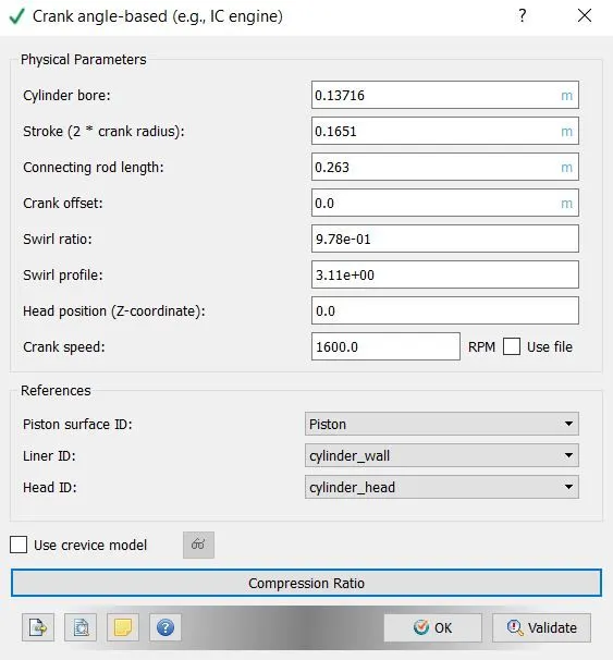
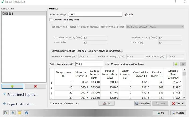
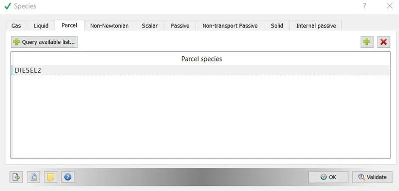
In gas simulation parameter therm.dat file was imported which contains gas thermodynamic data specifically related to IC engine. From the materials option parcel was enabled. In parcel simulation fuel Diesel2 was selected, which imported all the properties of fuel. Converge employs discrete Lagrangian parcels to simulate a special type of liquid in conjunction with spray modelling. In converge the Parcel simulation dialog box is for configuring properties of Lagrangian liquid parcels (such as for spray simulations).
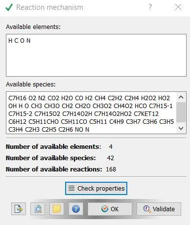
In reaction mechanism windows properties were checked to see the available species, which were imported by therm.dat file.
Diesel2 was defined in parcel option of species. SOOT and NOX were defined in internal passives.
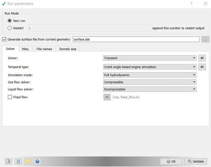
In run parameter transient was chosen as solver type with hydrodynamic simulation mode to simulate with the effect of liquid and gases. In temporal type crank angle-based engine simulation was chosen, because we wanted to run simulation on crank angles.
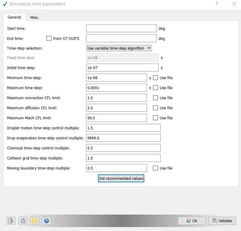
In simulation time parameter start and end time were specified in degrees, these were crank angles. Other parameters were defined as in the following image. Solver parameters were left as defaults.
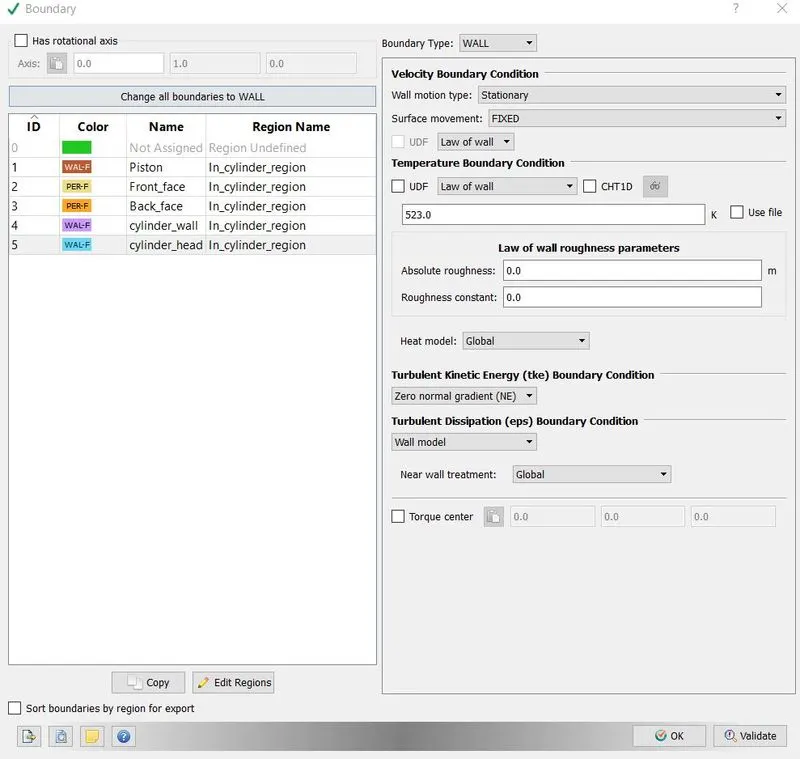
Boundaries were flagged as following
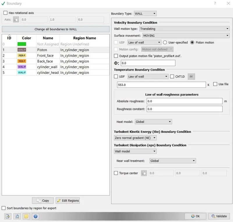
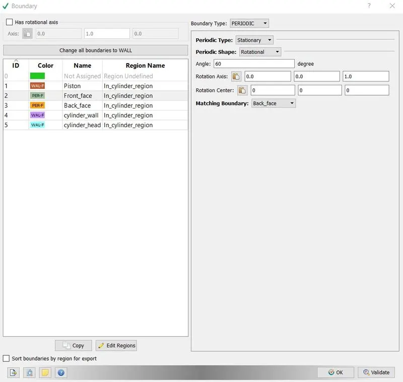
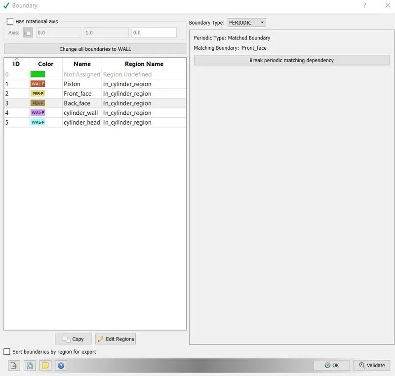
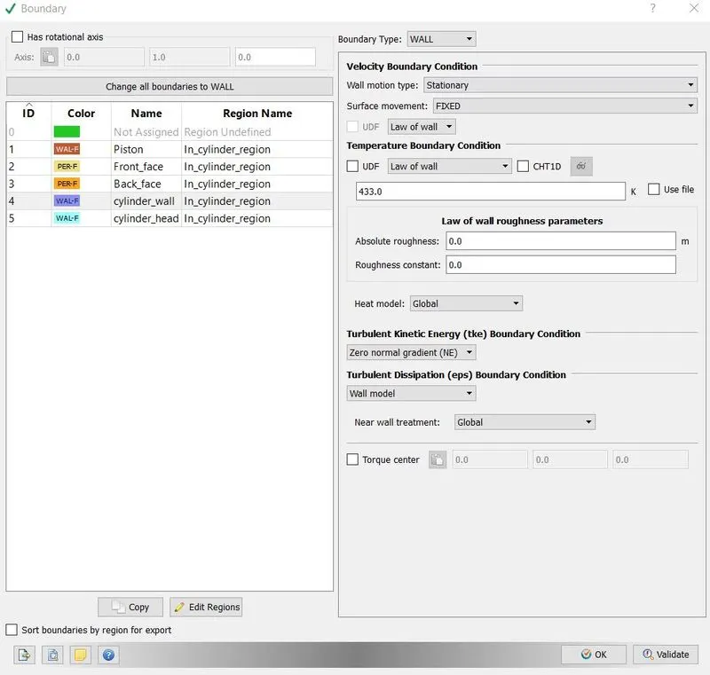
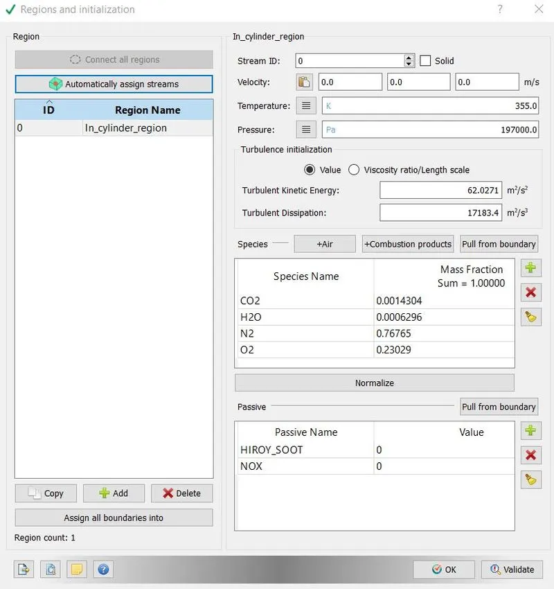
After this one region was defined, which was in cylinder. Since we were analysing emission characteristics of engine, so one region was enough. Species and their mass fraction were defined as follows.
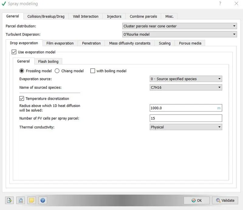
The Spray modelling dialog box is used to configure nozzles, injectors, boundary injections, injection rate-shapes, set various spray-related constants, and choose from several injection and drop models. We started with choosing drop evaporation option with frossling model, it determines how the radius of drop changes with time.
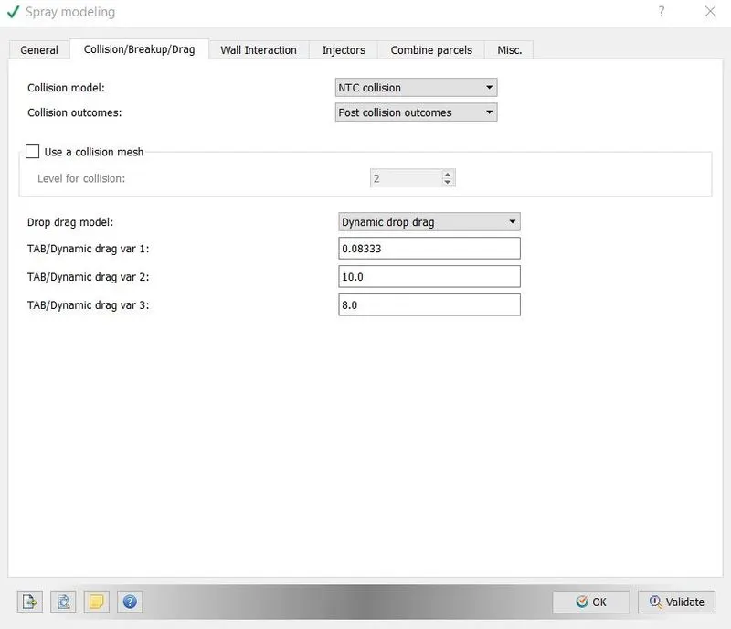
Converge contains the widely used O’Rourke and NTC collision models. These models are designed to estimate the number of droplet collisions and their outcomes in a relatively computationally efficient manner. We went with NTC model, since it is faster and more accurate than O’Rourke model.
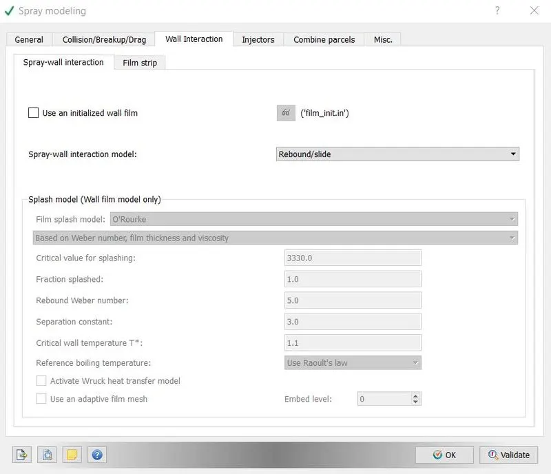
In wall interaction dialog box when define how liquid interacts with the walls and its parameter. wall film model is used for the modelling the interaction of liquid drops with solid surface and it comes with wall splashing option also. To determine the splash O’Rourke model is used and spray wall interaction wall film model was used.
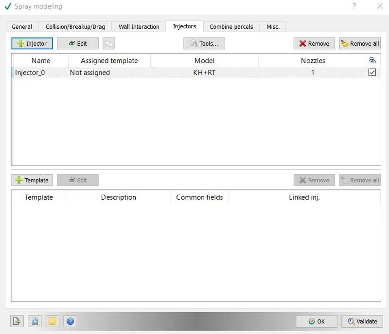
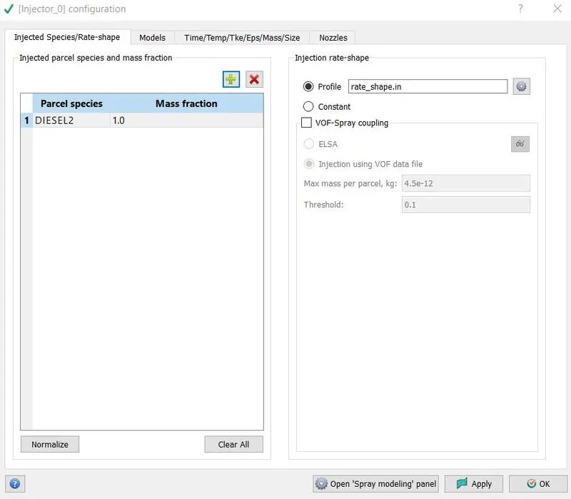
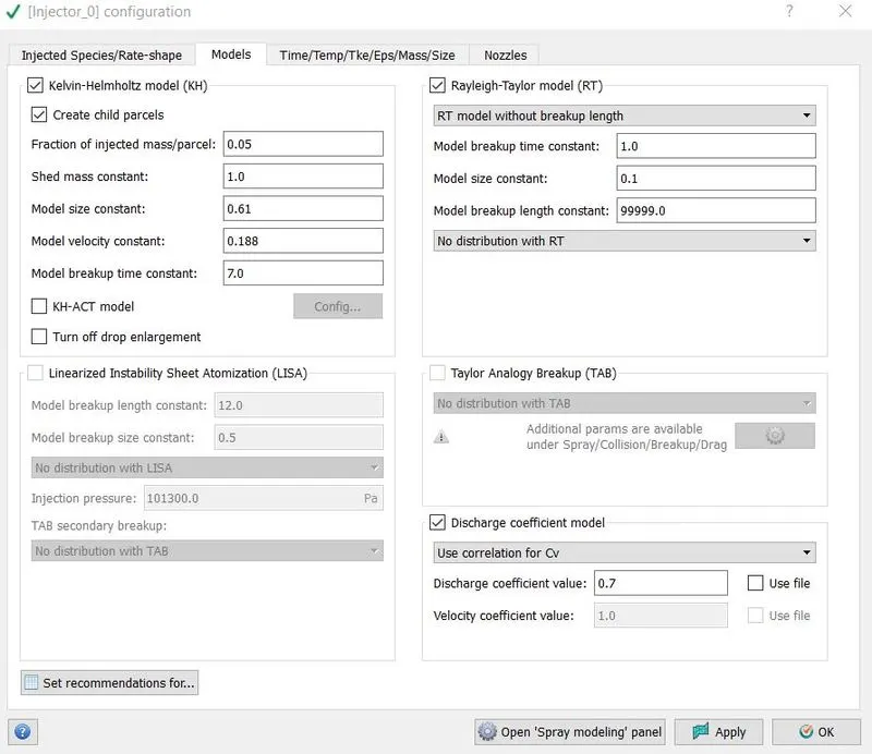
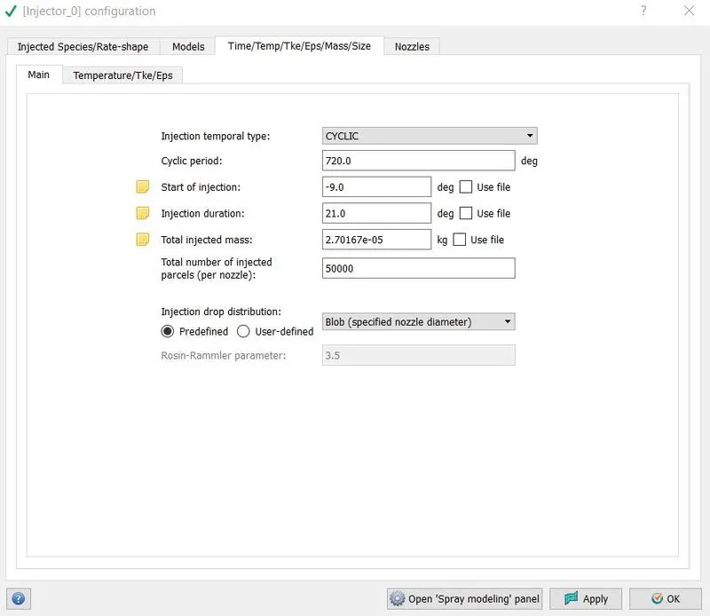
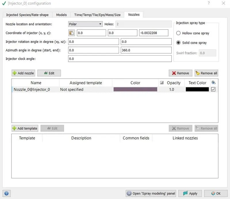
Converge offers two categories of liquid injection mechanisms: injectors and nozzles. An injector is a group of nozzles that have some of the same characteristics. Each injector can have any number of nozzles, each with its own hole size, cone angle, position, and orientation. We went with one nozzle with Kelvin-Helmholtz and Rayleigh-Taylor model. These models were responsible for prediction of liquid atomization and drop breakup. Time of injection, temperature, species and nozzle parameters were given
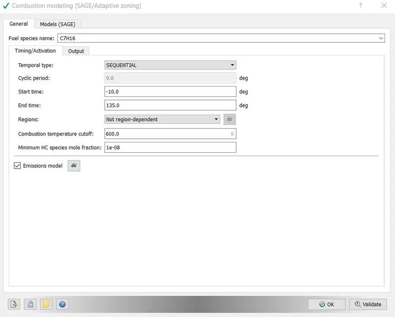
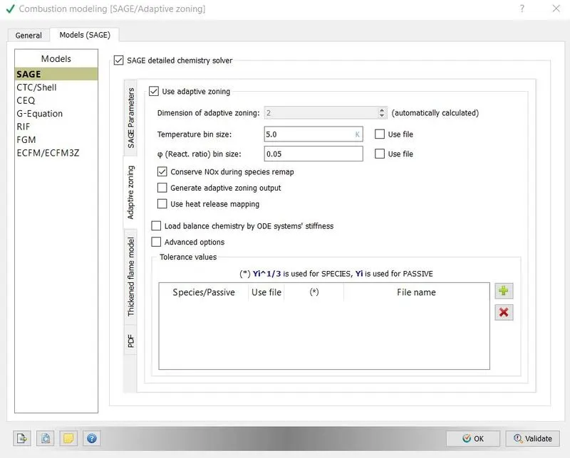
Combustion model in responsible for the chemical reactions and kinetics during combustion. We chose SAGE model, which solves for chemical reaction mechanism and its related parameters. In general setting, the time of combustion were defined in form of crank angles means combustion will take place between crank angle -10 to 135degrees.
Converge provides many models to simulate NOx and SOOT production. Species of interest such as CO, CO2, and unburned hydrocarbons are always calculated or interpolated in CONVERGE, provided they are included in the reaction mechanism file and are a part of the combustion model used by the simulation.
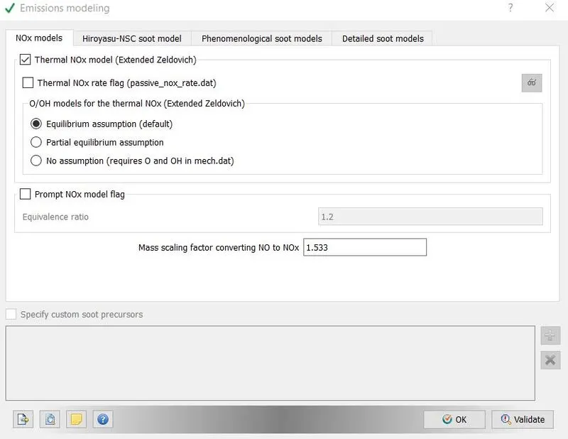
There are two NOx models one is thermal NOx and other one is prompt NOx. Prompt NOx model predicts formation of NO at low temperature fuel rich conditions and it is suitable for gas turbines. So, we chose thermal NOx model.
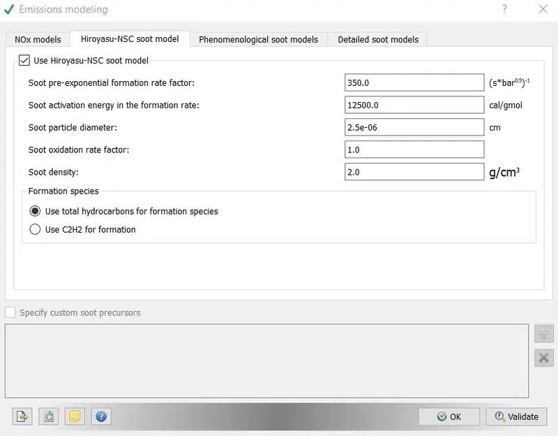
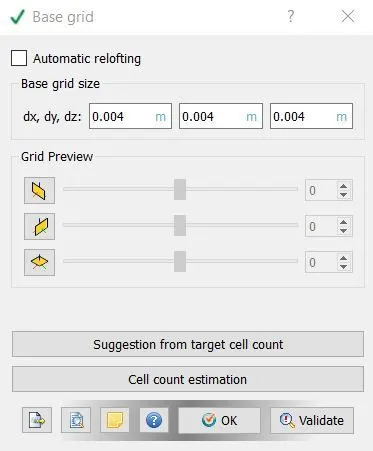
The soot models in converge describe the complex soot formation and oxidation process using several global steps, including soot inception, surface growth, coagulation, and oxidation. Phenomenological and detailed soot model are computationally expensive. So we went with empirical model. We chose k-epsilon turbulent model and base grid was chosen as 0.004m, since we would enable fixed embedding and AMR the global grid size won’t be a big problem
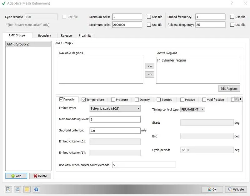
Adaptive mesh refinement option was enabled to get finer mesh. This option is very important because you cannot deploy same sized mesh on whole model. Velocity and temperature were two criteria which chosen for AMR. In velocity criteria sub grid criteria was 2m/s means above it, cell will be become finer by a factor of 2^n, here n is embedded level, in our case it is 2 and mesh will get finer by 4 times. Similarly, when sub grid temperature goes beyond 5K mesh will get finer by a factor of 4.
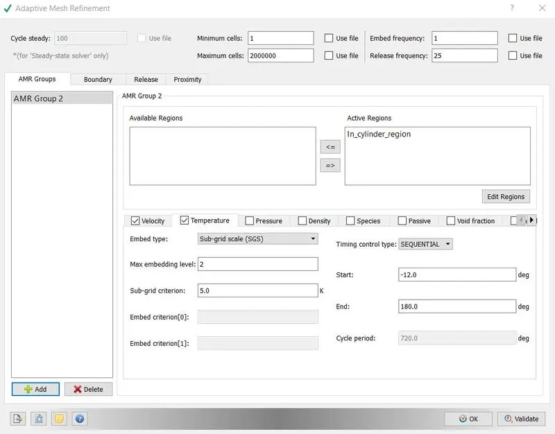
Fixed embedding option was enabled from grid control menu. Fixed embedding makes finer mesh of the basis of time or on the basis of crack angles. It is different from AMR because AMR option was dependent on the particular cell property. Fixed embedded was applied around nozzle, piston and around the boundary of cylinder. The parameter can be seen by following images.
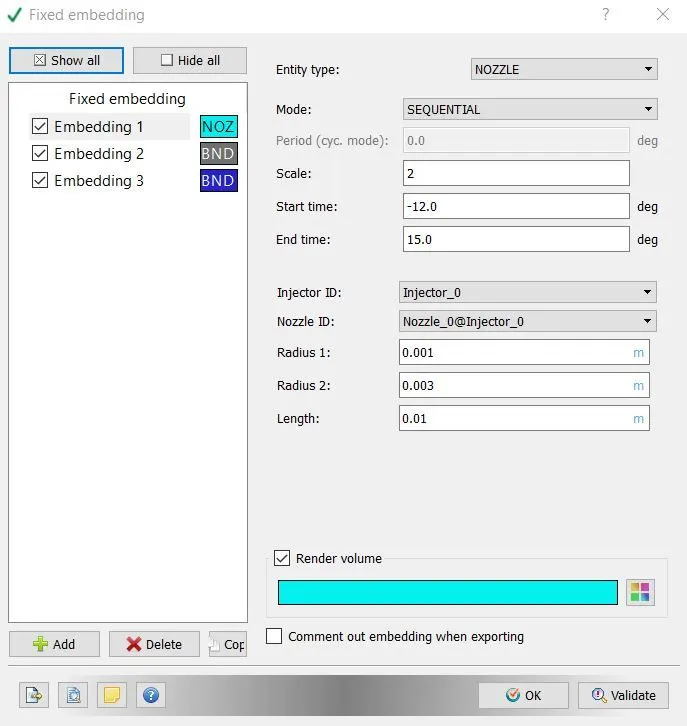
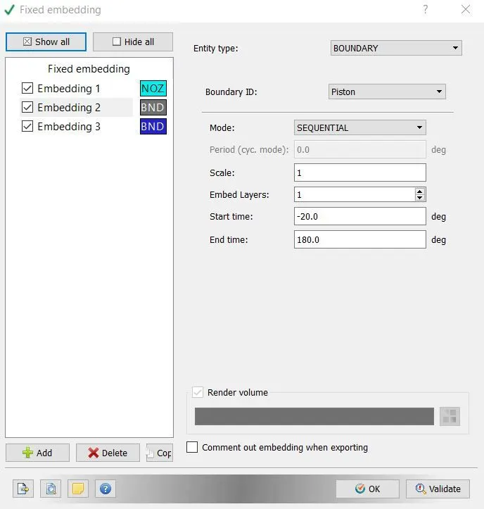
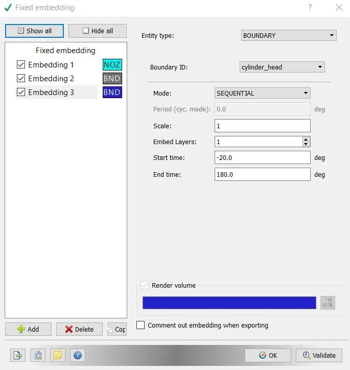
RESULTS:
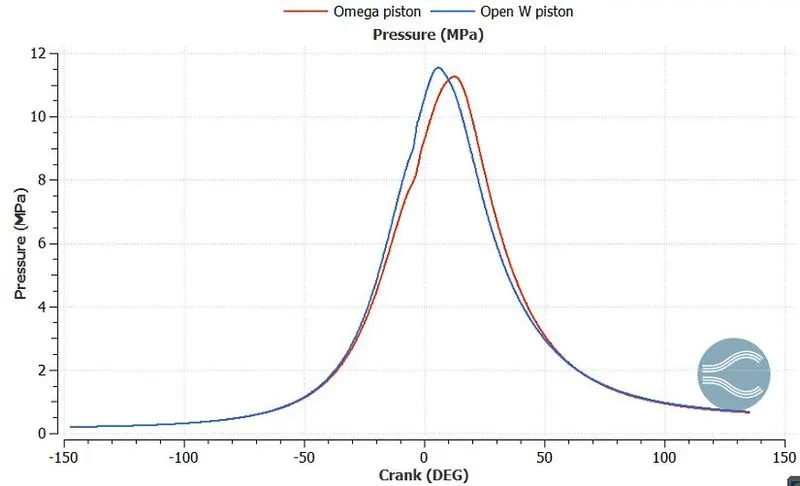
we can easily see that the open-W piston has the highest pressure than the omega piston.
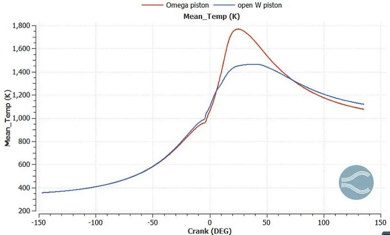
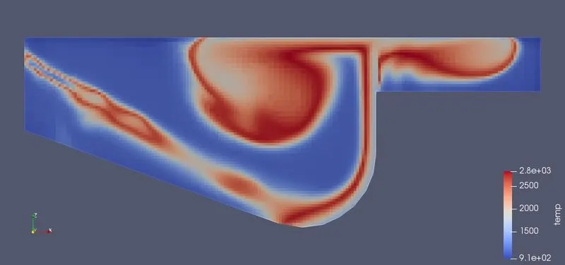
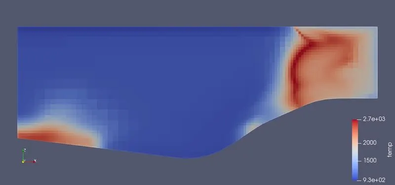
we can easily observe that the mean temperature is higher in omega piston as compared to the open-W case. This higher mean temperature produces the faster burning of fuel. This higher temperature is going to rise the NOx and soot formation.
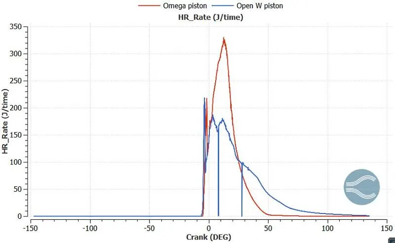
We can easily observe that Omega piston has a higher heat release rate than the open-W piston. The faster burning in the case of omega piston is the reason of higher heat release rate.
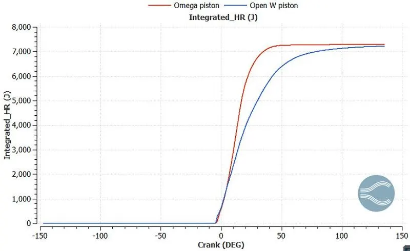
we can easily see that omega piston has the higher integrated_HR, this is happening due to high temperature in omega piston.
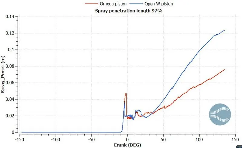
Spray penetration length was defined as the distance from the nozzle tip to the farthest spray region from the nozzle tip. In the above plot we can easily see that the open-W piston have long penetration than the Omega piston. The reason behnid the increase of penetration length in Open-W piston is that due to low temperature droplets are not disintegrated faster abd that's why do not evaporate faster. While in Omega piston case, due to instant increase in temperature droplets are evaporated faster.
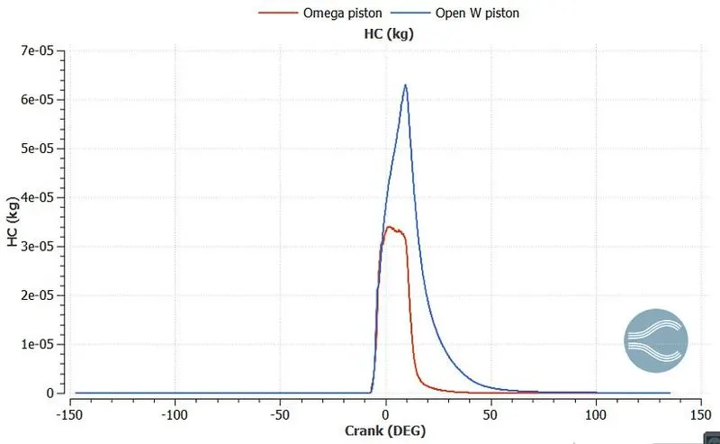
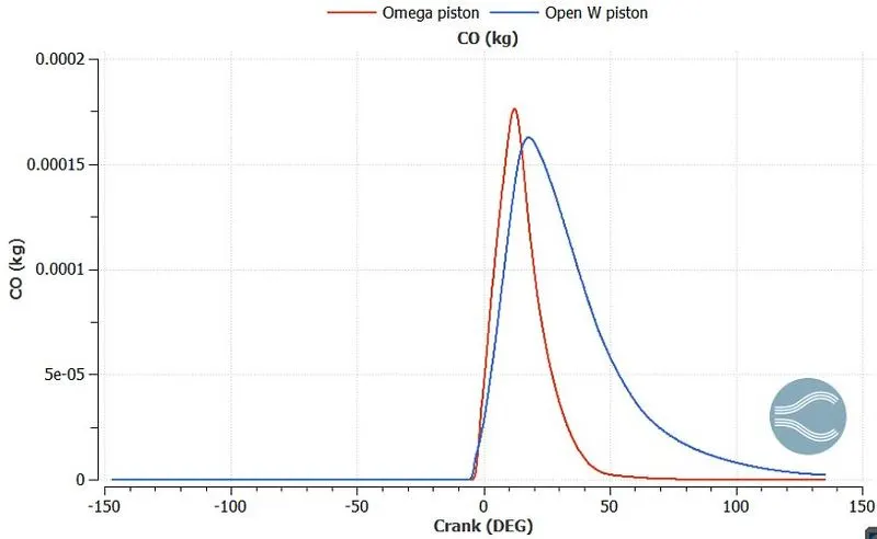
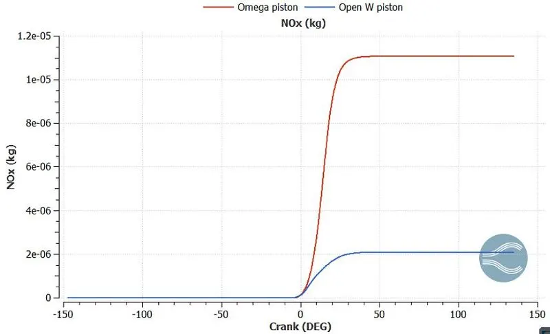
Power calculation for Omega piston using engine calculator
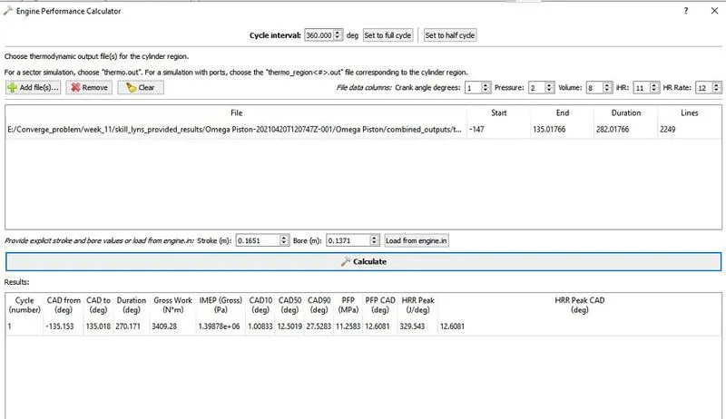
Work = 3409
Duration = 270.171
Power =work/sec
RPM = 1600
RPS = 26.667
1 rotation = 360 degree
DPS = 26.667*360 = 9600
Time(sec) = 270.171/9600 = 0.0281428
Power = 3409/0.0281428 = 121132.2256 KJ or 121.1322256 KW
Power calculation for Open-W piston using engine calculator
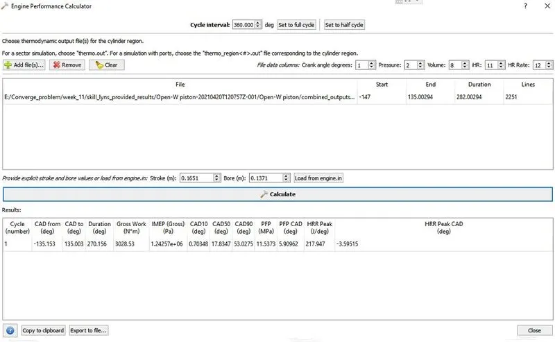
Work = 3028
Duration = 270.171
Power =work/sec
RPM = 1600
RPS = 26.667
1 rotation = 360 degree
DPS = 26.667*360 = 9600
Time(sec) = 270.171/9600 = 0.0281428
Power = 3028/0.0281428 = 107,594.12709 KJ or 107.594KW
CONCLUSION:
From the above plots, it is observed that the pressure and temperature inside the "omega" type piston are greater than the "open-w" type piston.The soot production i.e., incomplete burned particles that contained a large amount of amorphous carbon is very high in the open-w piston. On the other hand, the NOx i.e., Nitrogen Oxide produced by the open-w piston is far lesser than the omega piston.The carbon emissions from the omega pistons are also greater than the open-w piston(CO and HC), despite it emits fewer carbon di-oxides.Due to environmental restrictions and concerns, omega piston may not be suitable for current scenarios.