week-11 Joint creation and Demonstration
Aim: To demonstrate spherical, revolute, cylindrical, and translational joints between two rigid bodies and two deformable bodies.
Different Type of joints are:
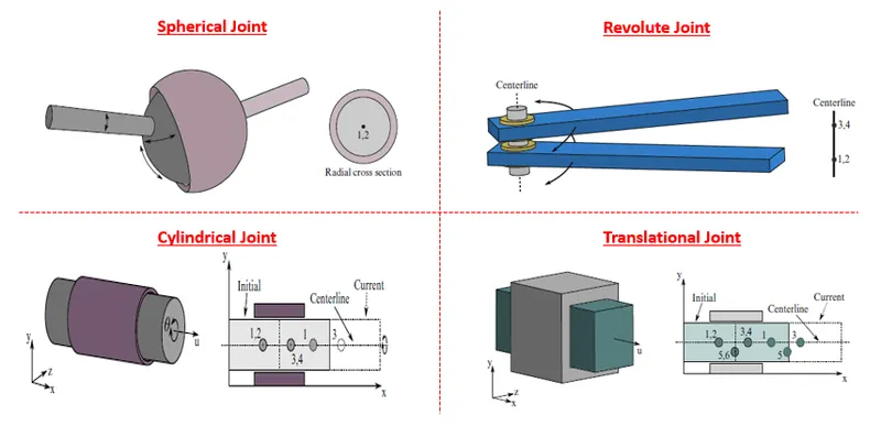
1. Revolute Joint b/w two rigid bodies:
1. First two cubes or geometries are created using shell elements (Element & Mesh -> 4N Shell -> Give Dimensions).
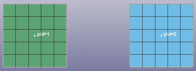
2. Now assign the material Id's and section Id two both parts.
3. Now we need to create 4 extra nodes which will be associated with these 2 parts. (Element tool -> Node editing)
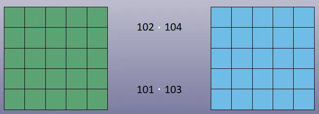
4. Now sepearte node set is created for moving nodes ( 102 & 104) and fixed node (101 & 103).
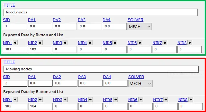
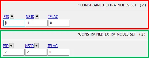
5. These extra nodes are free nodes, so first we need to associate these nodes to parts. 101 and 102 are associate to part1 and 103 & 104 to part 2 using *Constraint Extra Node Set.
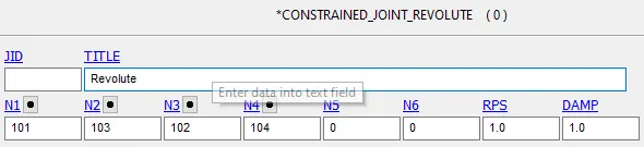
6. Now using constraint_joint Revolute joint is defined. N1 and N3 are 101 and 102 node belong to part1 and N2 and N4 are 103 and 104 node belong to part2.
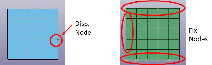
7. Now important boundary conditions are applied. Motion is provided in +z dir.
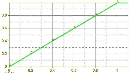
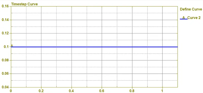
Displacement Curve is
8. Control_Timestep is used for system stability.
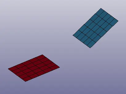
9. Final result after displacement of part is shown below
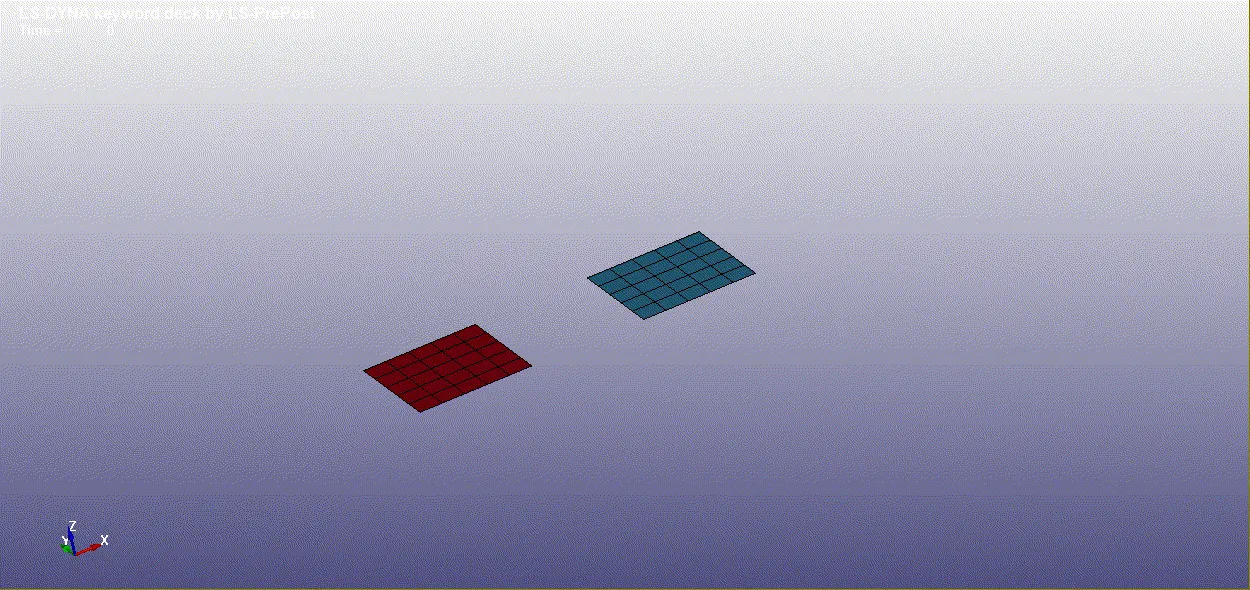
Animation:
2. Spherical Joint b/w two rigid bodies:
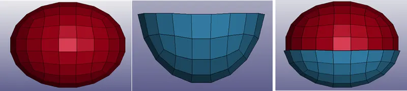
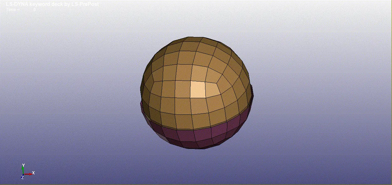
1. First two sphere are created with small offset using (Element & Mesh -> sphere shell -> Give Dimensions). Them half of elements of upper sphere are deleted converted to hemi-sphere.
2. Now material (MAT_20) is defined and section is also assigned to both parts.
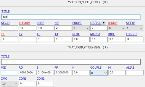
3. Now two nodes are created using Element tool, Node editing with node id 1000 and 2000. 1000 assigned to part 1 and 2000 to part 2.
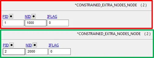
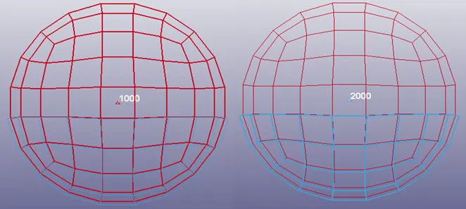
4. Now spherical joint is created using Constraint_joint_rigid.
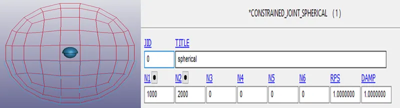
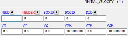
5. Now rotational velocity is given to outer sphere. And all other important boundary conditions are applied.
3. Cylindrical Joint b/w two rigid bodies:
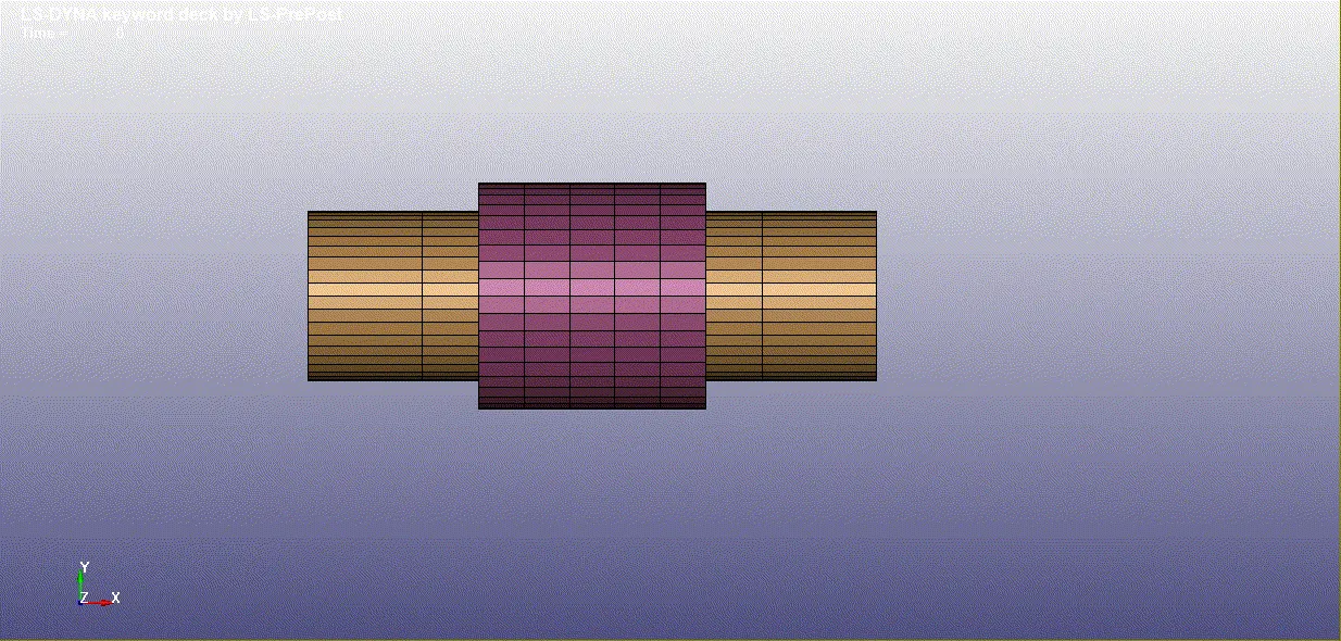
1. First two cylindres are created with small offset using (Element & Mesh -> cylinder shell -> Give Dimensions).
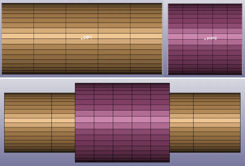
2. Material and section is assigned to both the parts.
3. Nodes are created using element and mesh. Node 1000 and 1001 assigned to part 1 and 2000 and 2001 is assigned to part2.
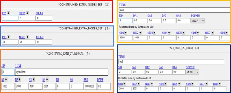
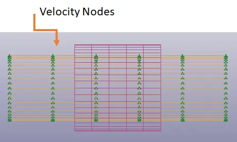
4. velocity is given to inner cylinder nodes. velocity in x-dir is given.
4. Translational Joint b/w two rigid bodies:
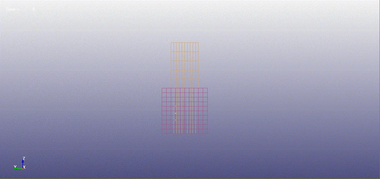
1. Frist two shell boxes are created using 4n shell.
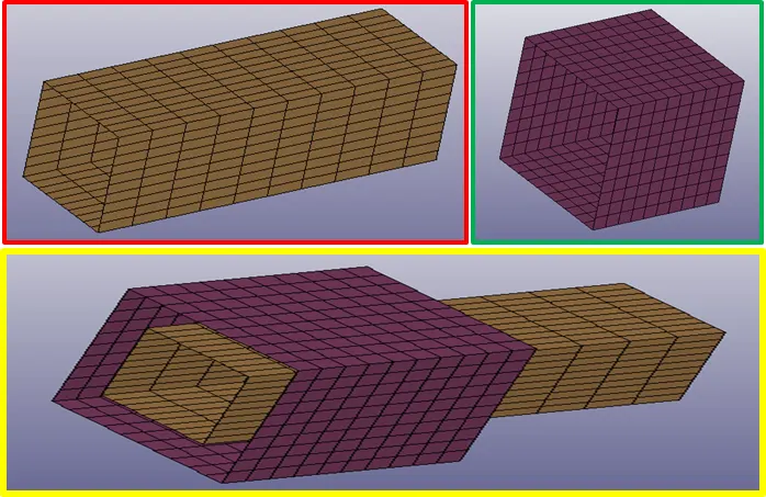
2. Material and section to both parts is assigned.
3. To define translation joint 3 pair of nodes are created. Two pair are coincident and third one is created at an offset to first two. node 1001, 1003, 1005 belong to part1 and 1002, 1004 & 1006 to part2.
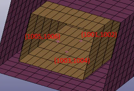
4. Velocity rigid body is given.

Animation:
------------------------------------------------------------------------------------------------------------------
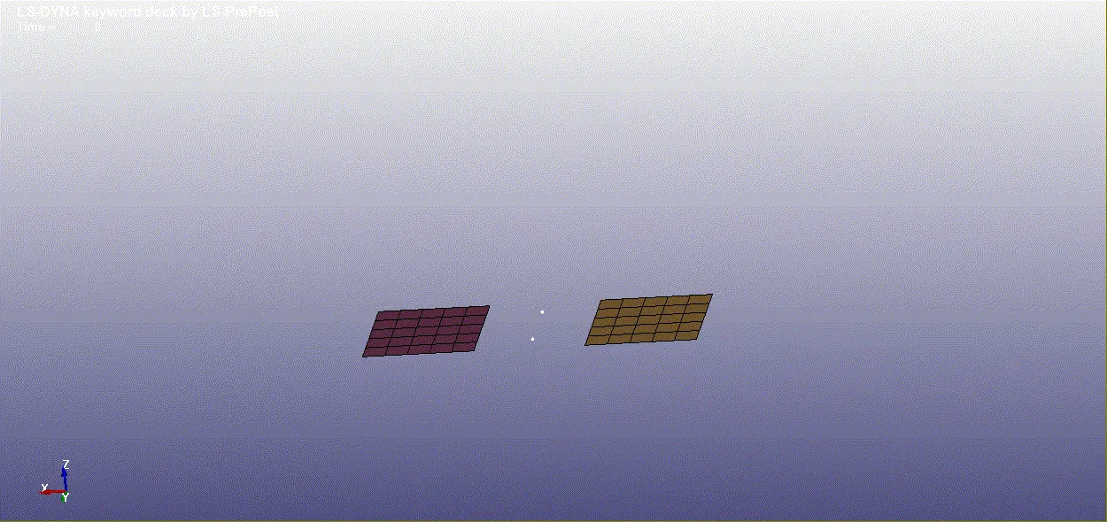
1. Revolute Joint b/w two deformable bodies:
1. Intialial steps are same upto material and section define.
2. Here constraint_nodal_rigid_body is used to define revolute joint. first four seperate nodes are created to define CNRB.
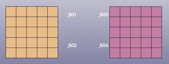
3. Now CNRB is created using create entity --> Constraint --> CNRB --> create
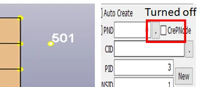
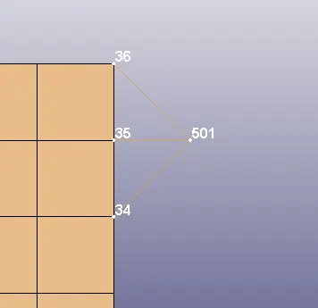
Similarly, all four CNRb are created.
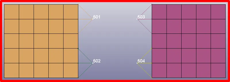
4. Now Node 501 and 503 should be coincide and Node 502 and 504 should coincide. that can be done through element tool --> transform --> translate --> Move.
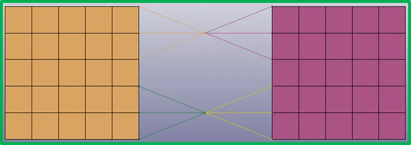
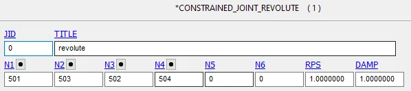
5. now revolute joint is defined using constraint joint revolute.
6. Boundary conditions are applied.
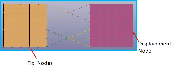
7. Animation
2. Spherical Joint b/w two deformable bodies:
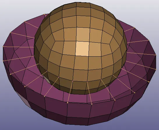
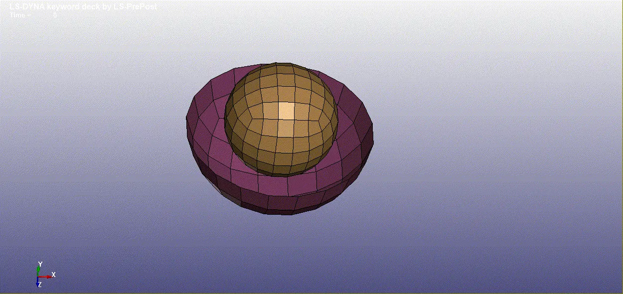
1. Here first material card is changed to elastic as no rigid part is present.
2. Also initial velocity rigid change to initial velocity.
3. CNRB is used instead of Constraint extra node.
4. CNRB are created.

Animation:
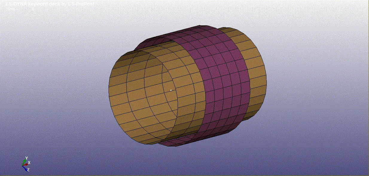
3. Cylindrical Joint b/w two deformable bodies:
1. First two cylindres are created with small offset using (Element & Mesh -> cylinder shell -> Give Dimensions).
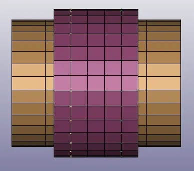
2. Material and section is assigned to both the parts.
3. Nodes are created using element and mesh. Node 1000 and 2000 assigned to part 1 and 1001 and 2001 is assigned to part2.
4. CNRB are created using created extra nodes.
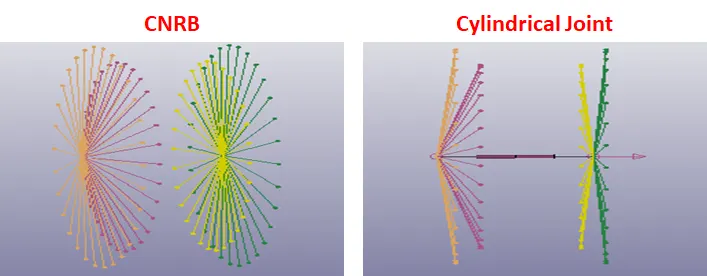
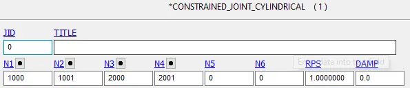
Animation:
4. Translational Joint b/w two deformable bodies
1. Frist two shell boxes are created using 4n shell.
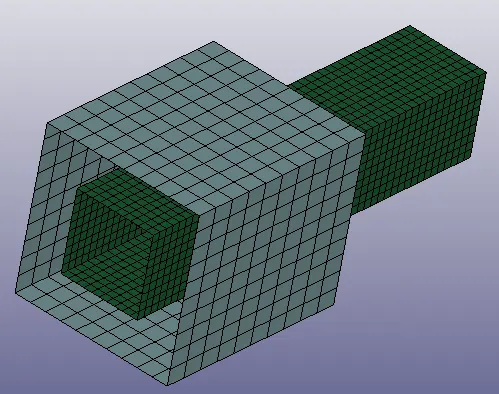
2. Material and section to both parts is assigned.
3. To define translation joint 3 pair of nodes are created. Two pair are coincident and third one is created at an offset to first two. node 10000,20000,30000 belong to part1 and 10001,20001 & 30001 to part2.
4. CNRB are created using these nodes.
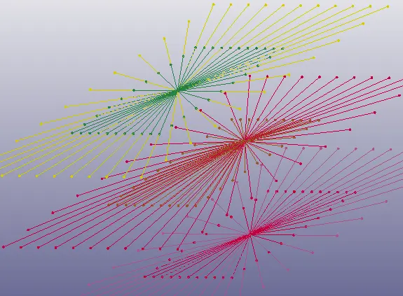

Animation:
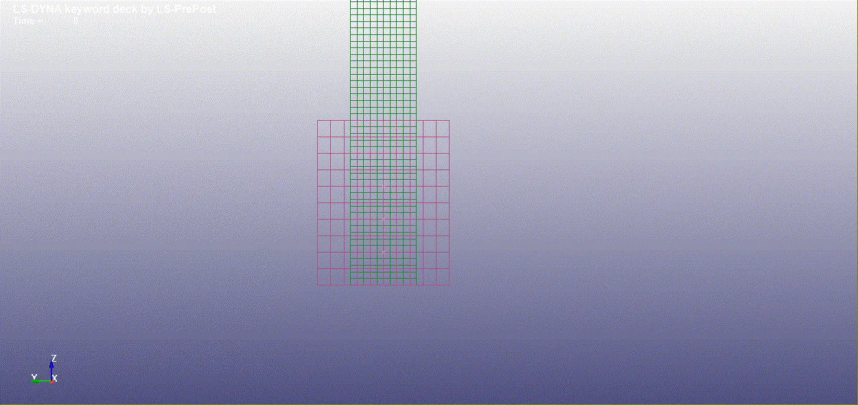
Learning Outcomes:
1. Learned to create different type of joints ( spherical, translational , cylindrical & revolute) for both deformable and rigid bodies.