week-11 Joint creation and Demonstration
report week 11
Aim: Use the manual (*CONSTRAINED_JOINT keyword) demonstrate spherical, revolute, cylindrical, and translational joints between two rigid bodies and two deformable bodies.
Procedure:
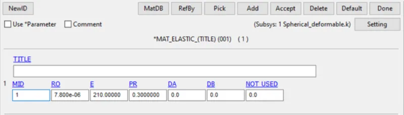
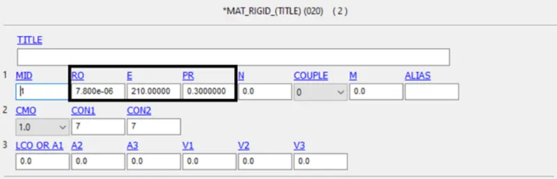
Material: There are two material will be used in this case: MAT_ELASTIC 001 and MAT_RIGID 020
They are showing as follow
Section:
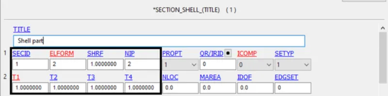
Sections are the same in each case for both parts with thickness 1 mm.
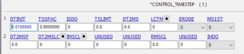
Control setting: in TERMINATION card, ENDTIM is 5ms, in TIMESTEP card, DTINIT is 0.01.

Spherical Joint:
Rigid:
First, use shape mesher to create two sphere shell, delete a half element on the bigger one.
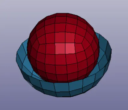
Create two nodes in the same location (center of red sphere)
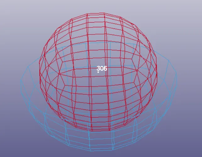
One node is assigned to part one, another is assigned to part two using


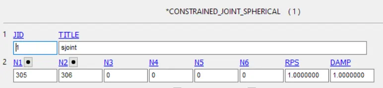
Create spherical joint to connect thoes two points.
Create initial velocity

Result animation is attched in the uploaded document d3plot file
Deformable:
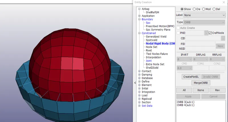
Create geometry as above, create two points in same location, use CNRB to connect thoes two points to two parts.
Use INITIAL_VELOCITY instead of INITIAL_VELOCITY_RIGID_BODY
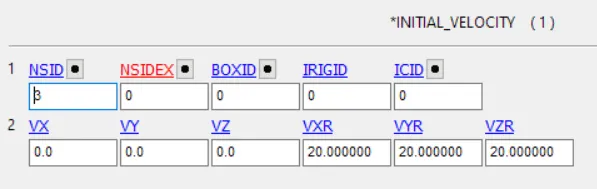
Result animation is attched in the uploaded document d3plot file
Revolute Joint:
Rigid:
Use Shape Mesher to create two 4N Shell.
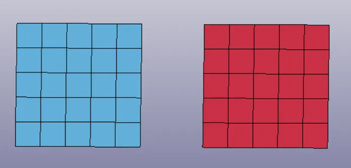
Create 4 points between them, 73,74, 75,76. 73 and 75 in same location, 74 and 76 in same location.
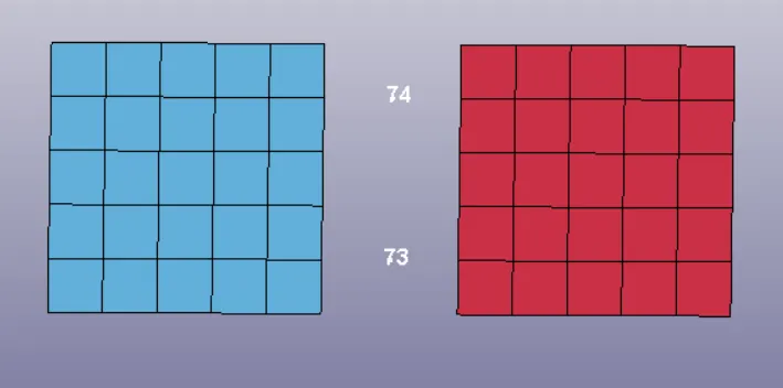
Create node set, assign 73 74 to one part and 75 76 to another part.


Create revolte joint to connect nodes
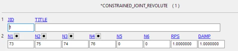
Boundary condition
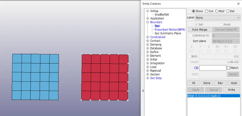
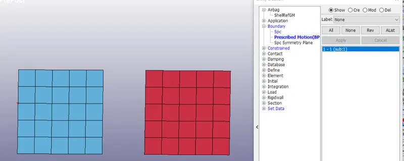
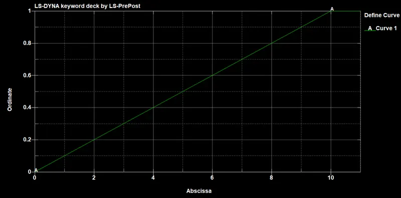
Displacement curve
Result animation is attched in the uploaded document d3plot file
Deformable:
Create geometry and 4 nodes. Use CNRB to connect nodes to parts
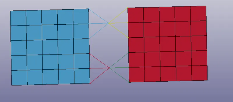
Load curve and boundary condition are the same as rigid case.
Result animation is attched in the uploaded document d3plot file
Cylindrical Joint
Rigid:
Create geometry using Shape Mesher
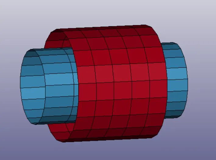
Create 4 nodes in the center of cylinders, 241-244, 241 and 243 in same location, 242 and 244 in same location.
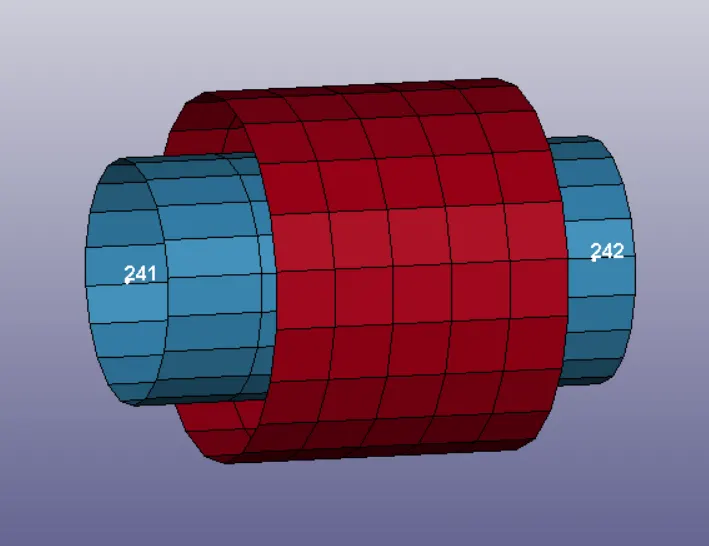
Assign 241 and 242 to part 1 and 243 244 to another part

Use Cylinderiacal Joint to connect nodes and parts
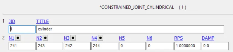
Create initial velocity

Result animation is attched in the uploaded document named d3plot file
Deformable:
Create geometry and create thoes nodes, use CNRB to create connections, 241 and 242 to part 1 and 243 244 to part 2.
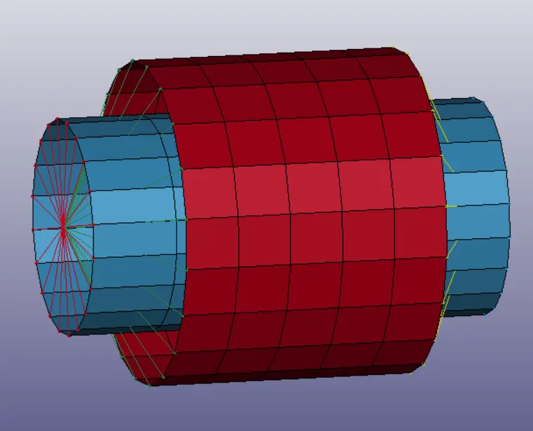
Use INITIAL_VELOCITY instead of INITIAL_VELOCITY_RIGID_BODY
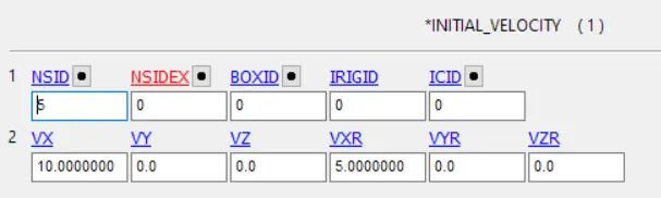
Result animation is attched in the uploaded document named d3plot file
Transitional Joint:
Rigid:
Use Shape Mesher to create geometry
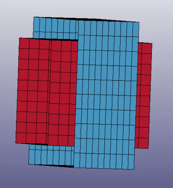
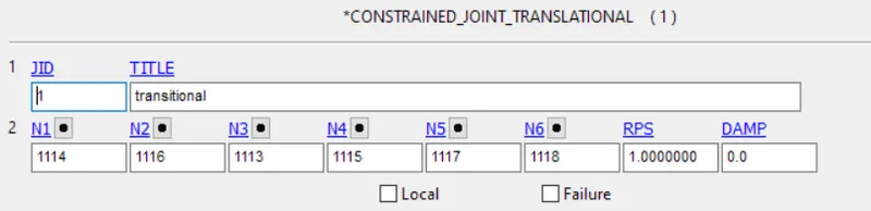
Create nodes 1113-1118, 1113,1114 and 1117 belong to one part and 1115,1116 and 1118 belong to another
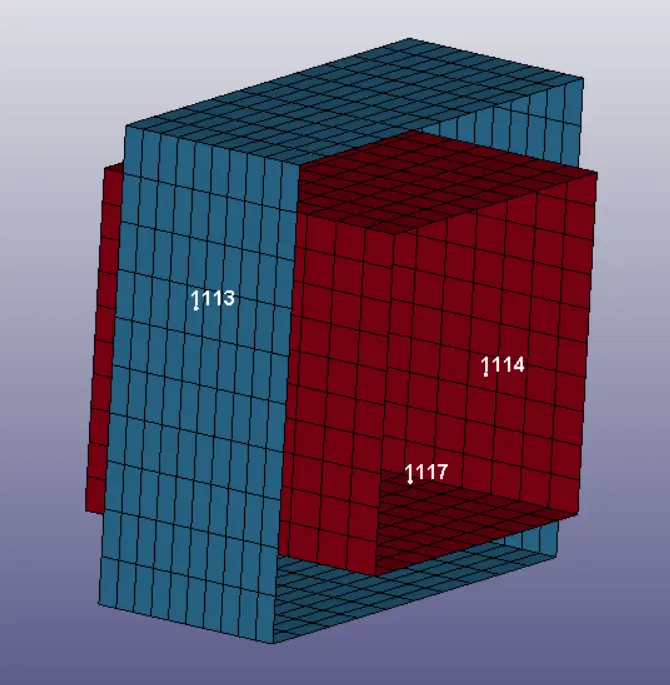
Assign nodes to each parts
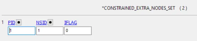
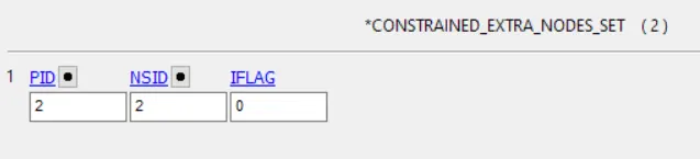
Use translational joint to connect nodes
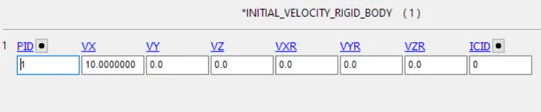
Create initial velocity
Result animation is attched in the uploaded document d3plot file
Deformable:
Create grometry and nodes. Use CNRB to create connection
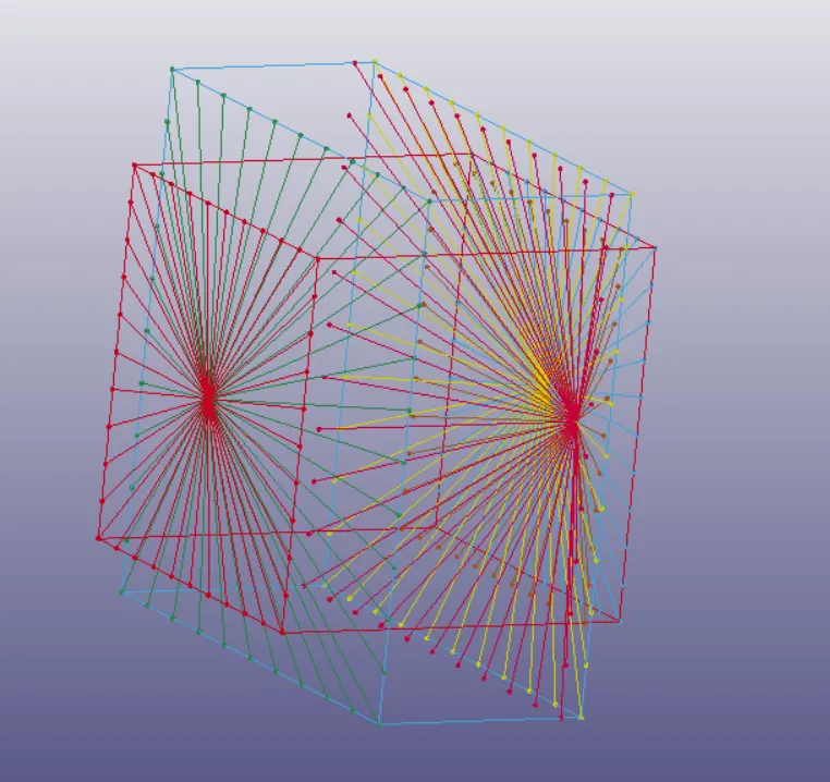
Use INITIAL_VELOCITY instead of INITIAL_VELOCITY_RIGID_BODY
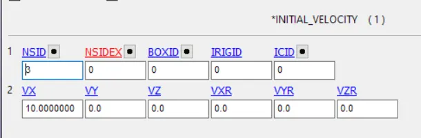
Result animation is attched in the uploaded document d3plot file
Conclusion: Spherical, revolute, cylindrical, and translational joints between two rigid bodies and two deformable bodies are created. There are some difference between rigid and deformable bodies.
1. Use elastic material for deformable body, use rigid material for rigid body.
2. Use CNRB for deformable body, use CONSTRAINED_EXTRA_NODES for rigid body.
3. Use INITIAL_VELOCITY for deformable body, use INITIAL_VELOCITY_RIGID_BODY for rigid body.