week-11 Joint creation and Demonstration
AIM:
Using the manual(*CONSTRAINED_JOINT) keyword demonstrate Revolute, Spherical, Cylindrical and Translational joints between two Rigid bodies and two deformable bodies.
THEORY:
PROCEDURE:
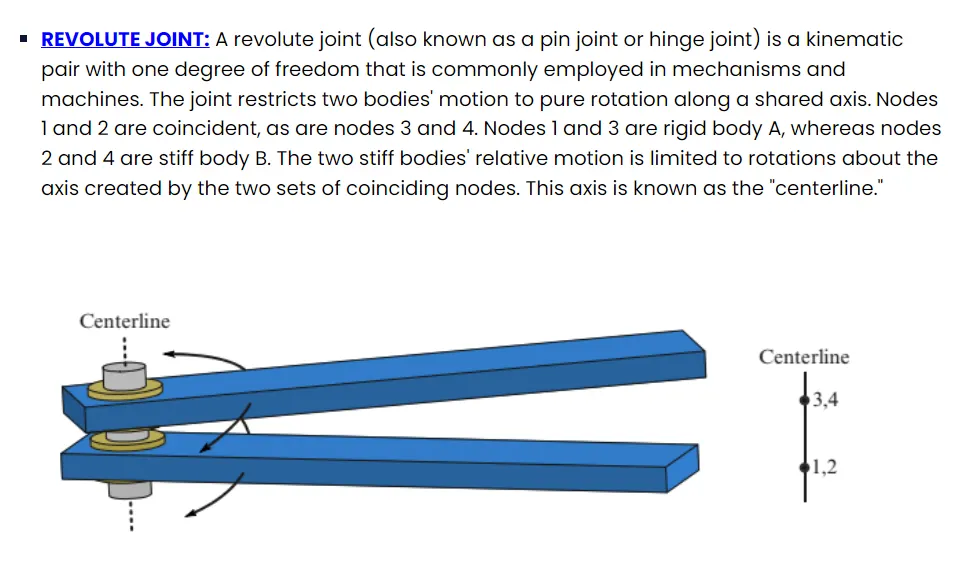
REVOLUTE JOINT:
RIGID BODIES:
STEP 1: MAKE 4N SHELL BOX.
element and mesh > shape mesher > 4N shell
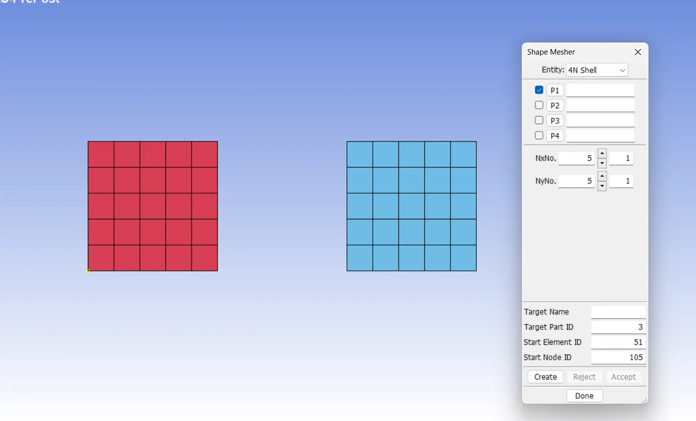
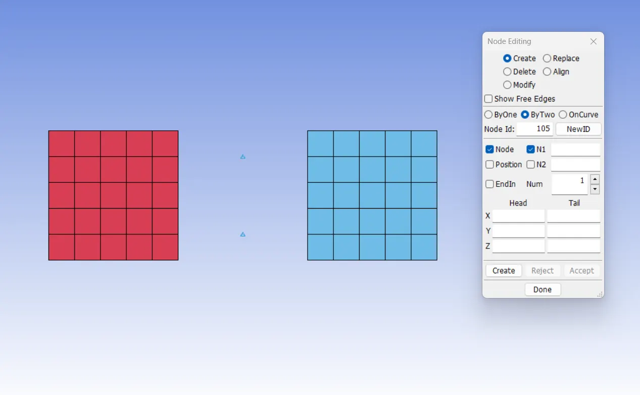
STEP 2: CREATE FOUR EXTRA NODES BETWEEN TWO BOXES.
element tools > node editing
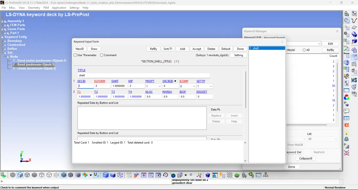
STEP 3: DEFINE SECTION CARD.
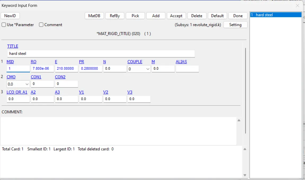
STEP 4: DEFINE MATERIAL CARD.
STEP 5: CREATE TWO NODE SET.(101-102,103-104)
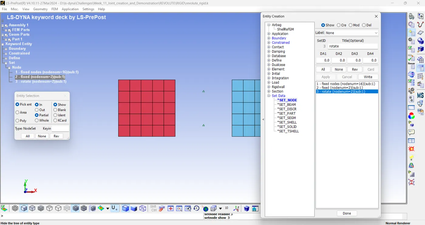
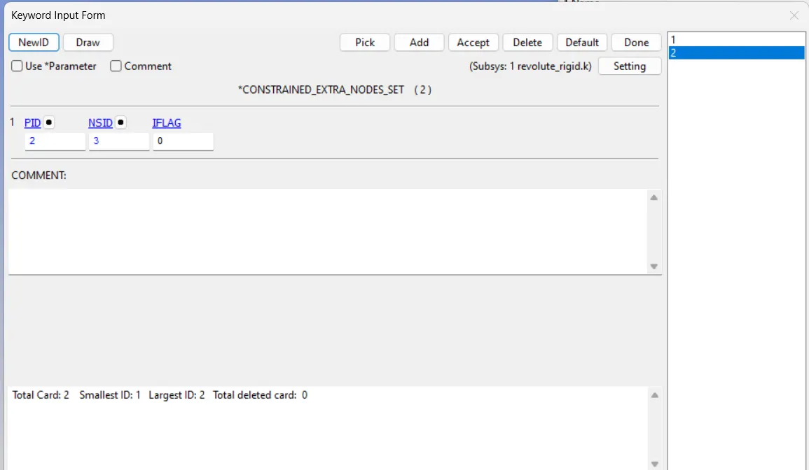
STEP 6: DEFINE *CONSTRAINED_EXTRA_NODE_SET.
The node set developed earlier are designated to this card accordingly.
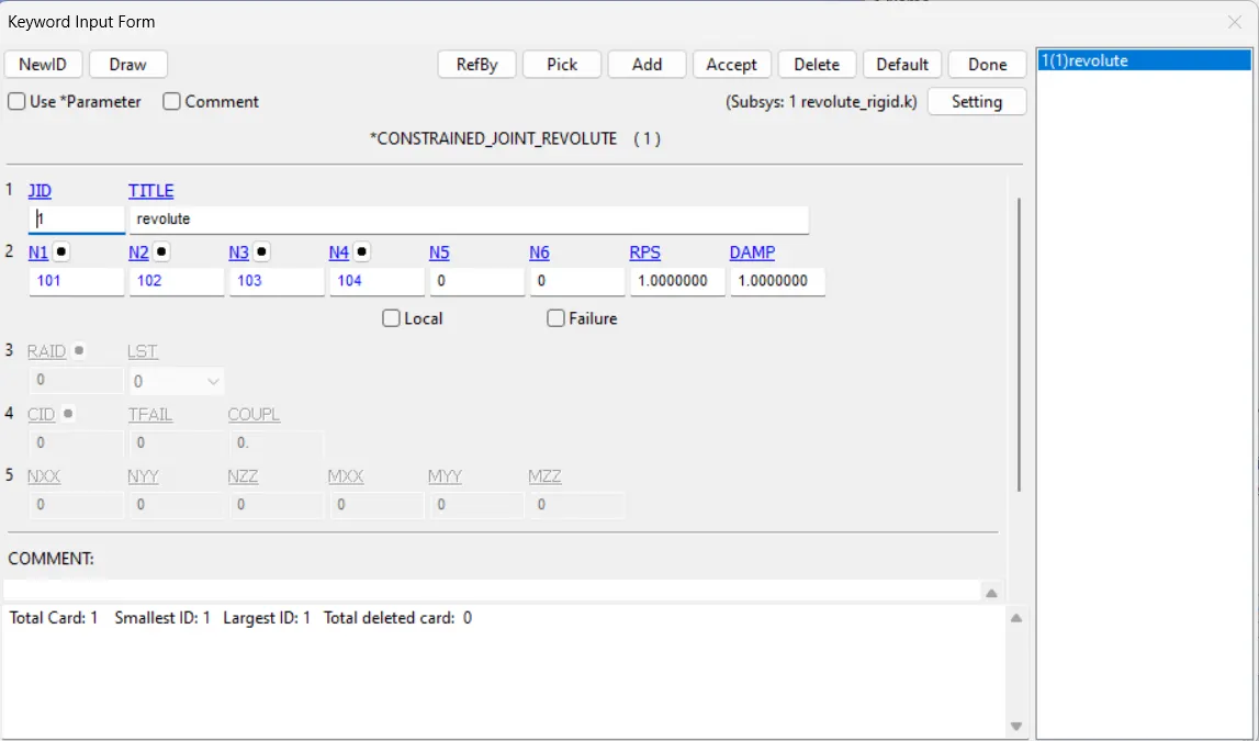
STEP 7: DEFINE *CONSTRAINED_JOINT_REVOLUTE
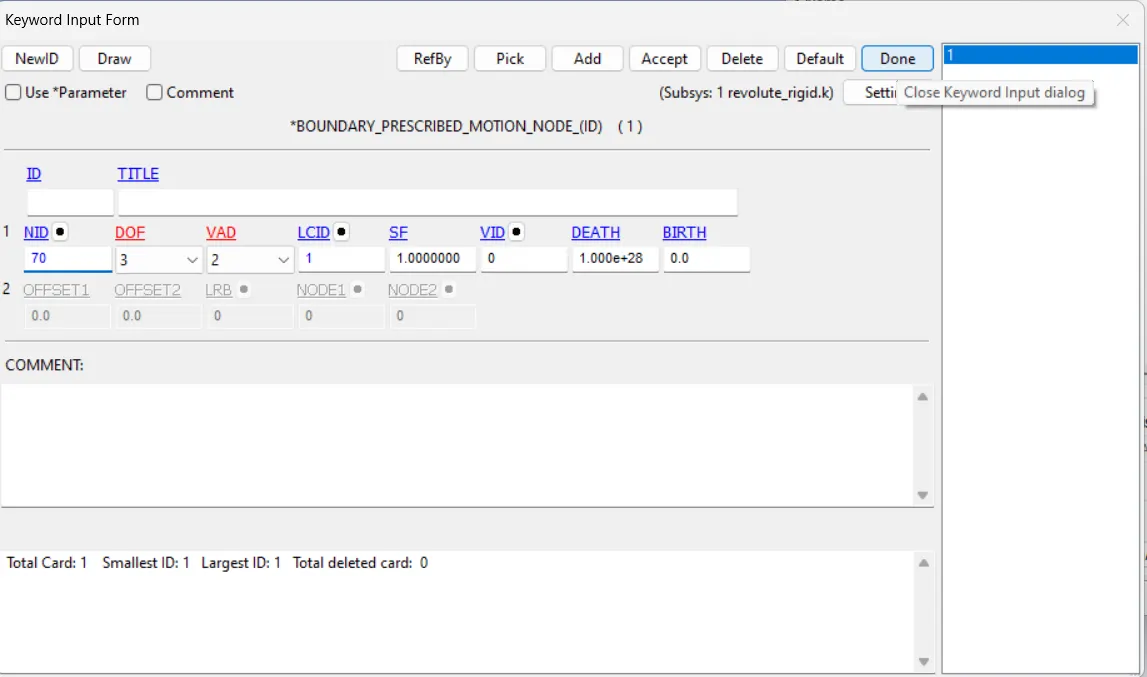
Here we use a SPC card for one part that remains constrained in all axis and give a prescribed motion along the z-transitional axis with respect to the load curve id generated earlier.
Furthermore, Time step, Control termination, Binary d3plot card are inserted.
Then run the file.
DEFORMABLE BODIES:
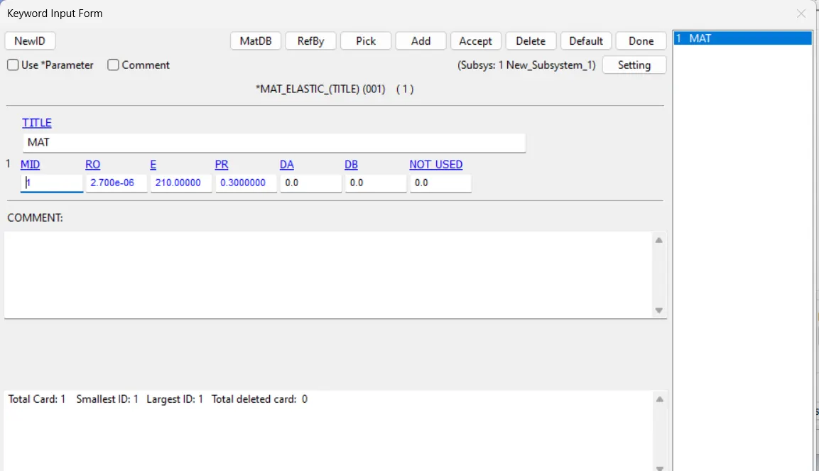
In the case of deformable bodies, we can choose *MAT_ELASTIC.
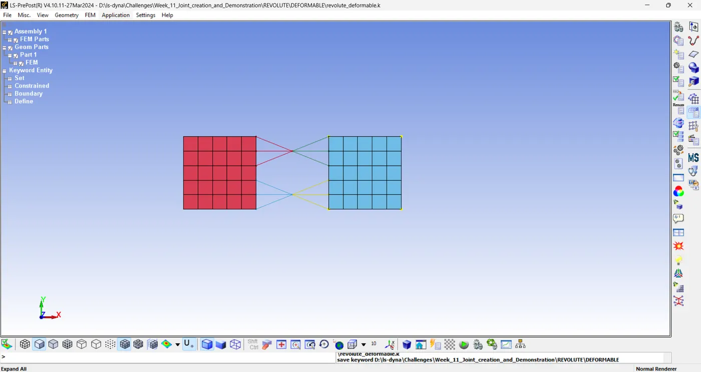
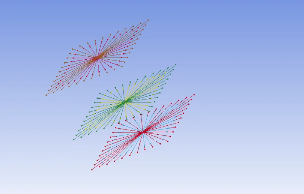
In the case of deformable bodies, we create Constrained_Nodal_rigid_bodies which are connected to each principal node set. So in this case we don't use the Constrained_Extra_Node_set card. The step-by-step process is done with utter caution otherwise the CNRB will misbehave during simulations. The process for the Revolute joint case is shown below, also in PNID, we put the value of our principal nodes and then select other nodes from top to bottom of each body.
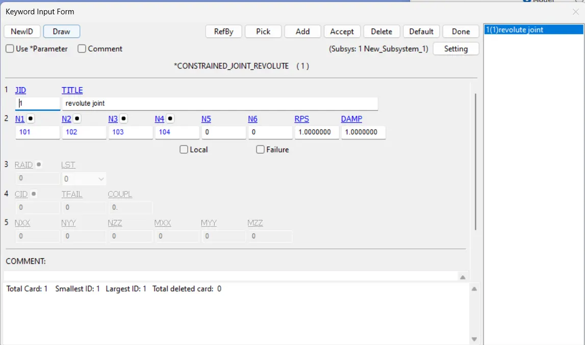
The rest of the process is followed the same as done in the rigid body case earlier except change some values as assigned below.
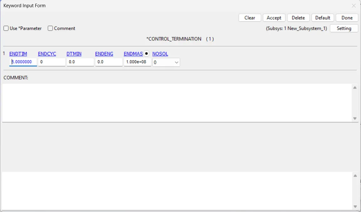
Then run the file.......
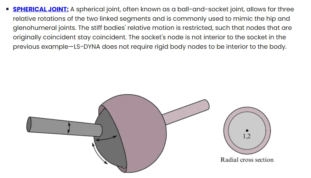
SPHERICAL JOINT:
RIGID BODIES:
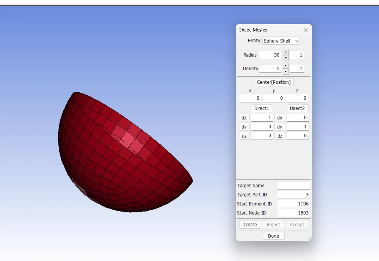
STEP 1: MAKE TWO CONCENTRIC SHELL SPHERE.
element and mesh > shape mesher > sphere shell
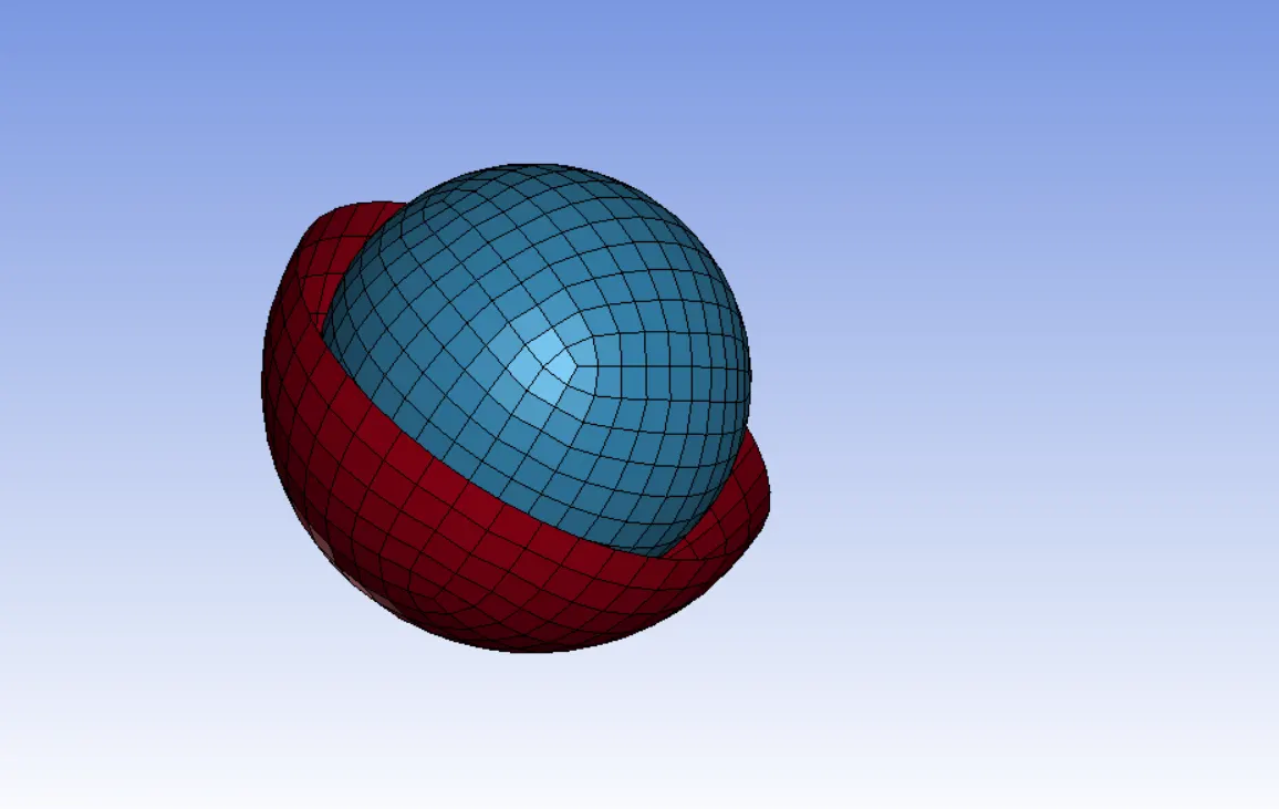
STEP 2: CREATING TWO EXTRA NODES.
Two nodes namely 1501 and 1502 are created in this type of joint which are constituted to each sphere shell respectively.
STEP 3: DEFINE *CONSTRAINED_EXTRA_NODE_SET.
These extra nodes are inputted in to this card.
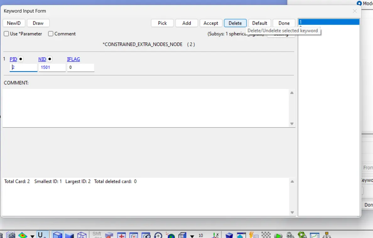
STEP 4: DEFINE *CONSTRAINED_JOINT_SPHERICAL.
This card is used for the spherical joint model , 1501 and 1502 nodes are inserted in sequence for this card.
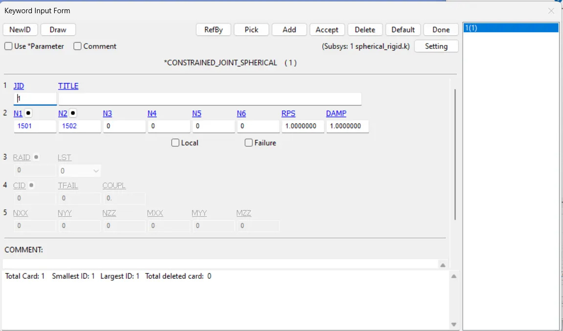
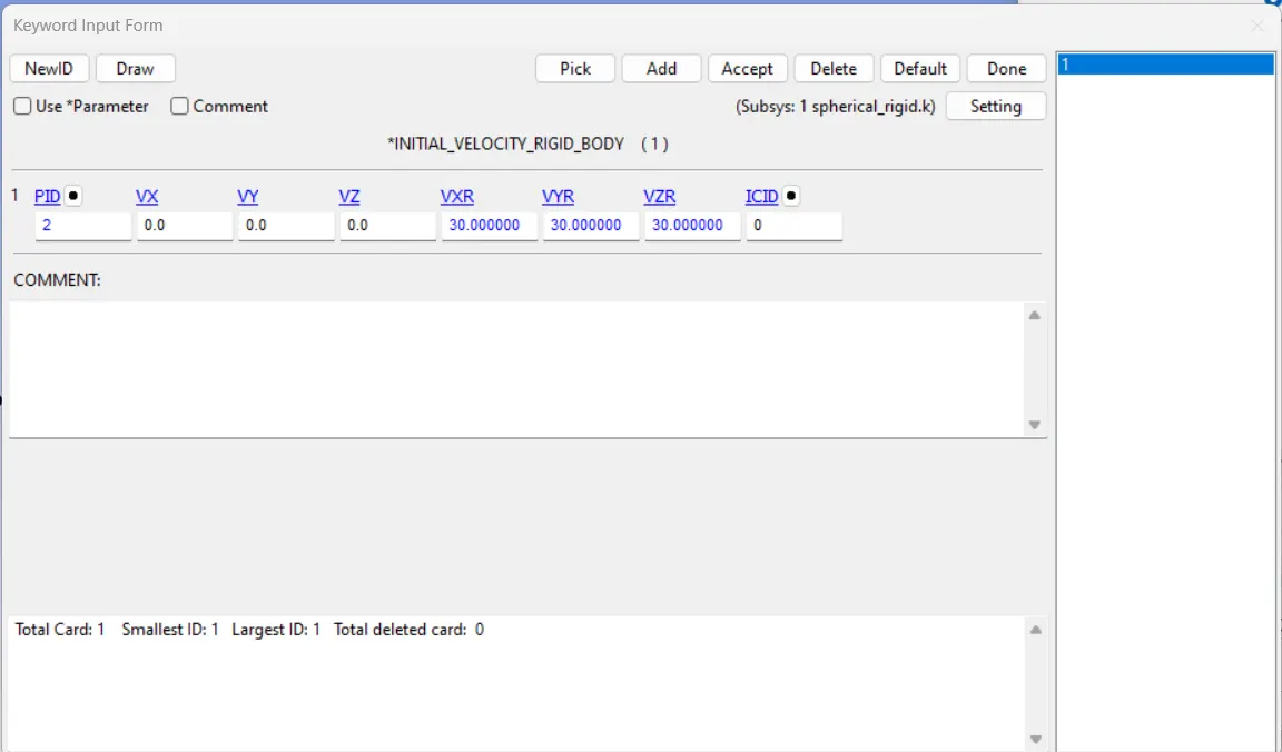
STEP 5: DEFINE VELOCITY.
We use *INITIAL_VELOCITY_RIGID_BODY .We provide an initial velocity of 30 mm/ms in X Y Z rotational direction only.
STEP 6: DEFINE RIGID MATERIAL
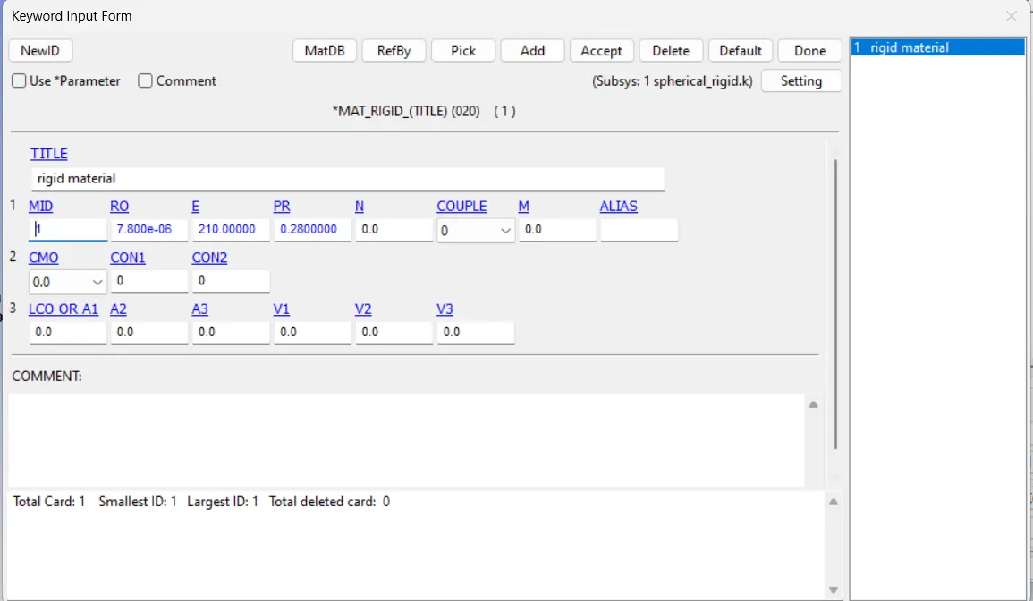
Termination time, Data base cards and other mandatory cards required for the joint creation and demonstration process are the same as shown earlier.
THEN RUN THE FILE....
DEFORMABLE BODIES:
In the case of deformable bodies , we use the MAT_ELASTIC card.
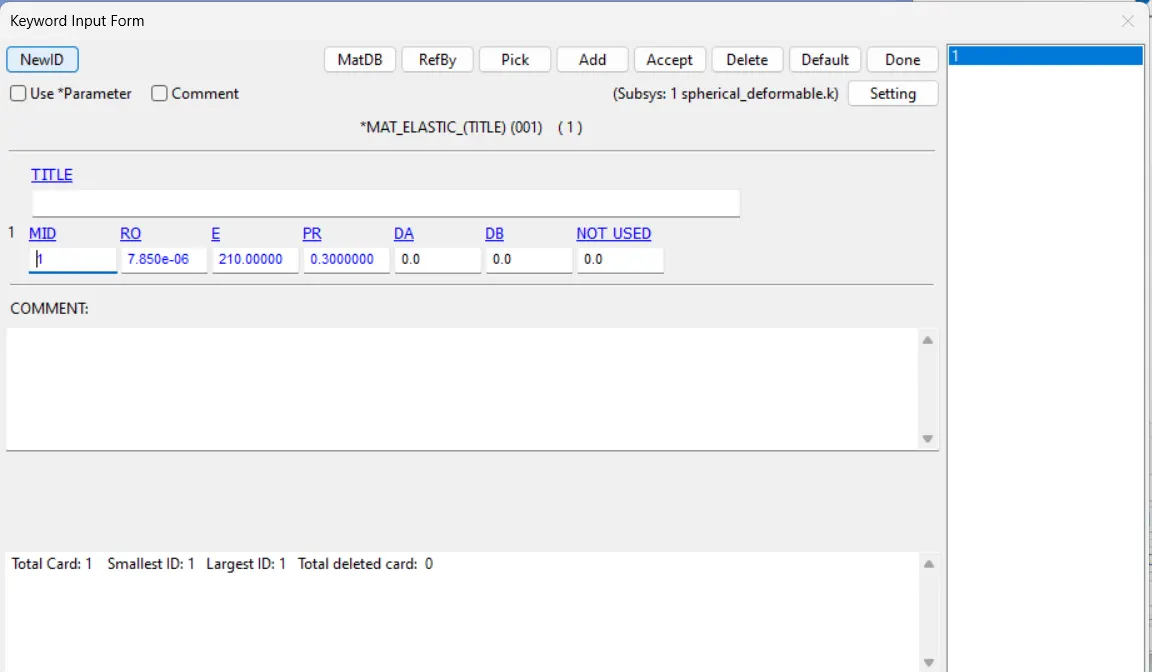
In this case CNRB's are created for each sphere,
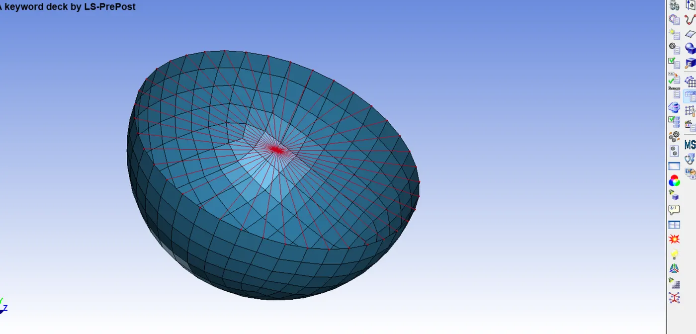
Rest of the card are repeated like in the rigid body case for the spherical joint.
THEN RUN THE FILE......
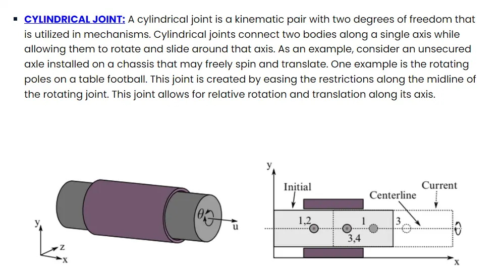
CYLINDRICAL JOINT:
RIGID BODIES:
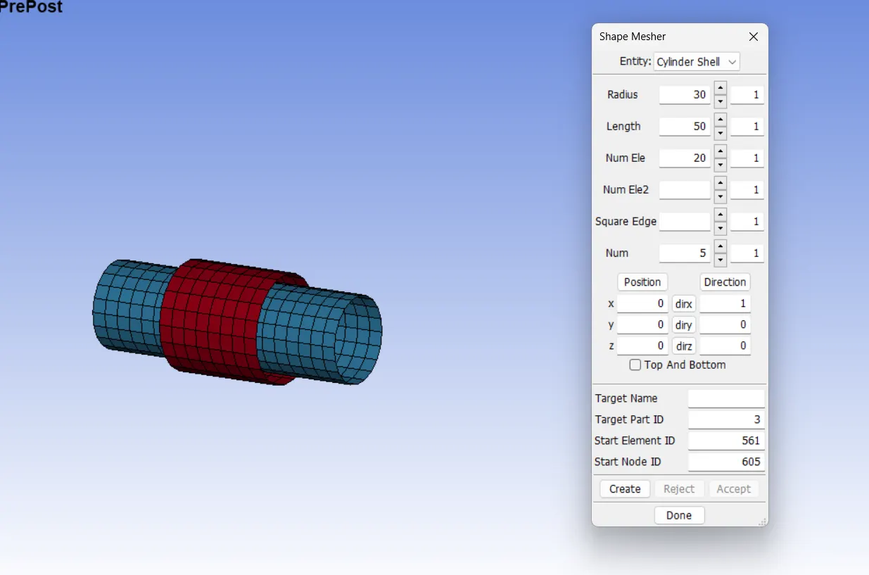
STEP 1: MAKE TWO CONCENTRIC CYLINDER SHELL.
STEP 2: DEFINE MATERIAL
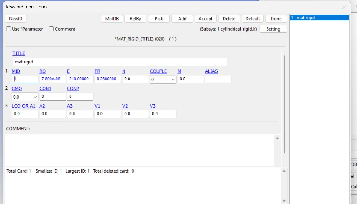
Define SECTION and PART .....
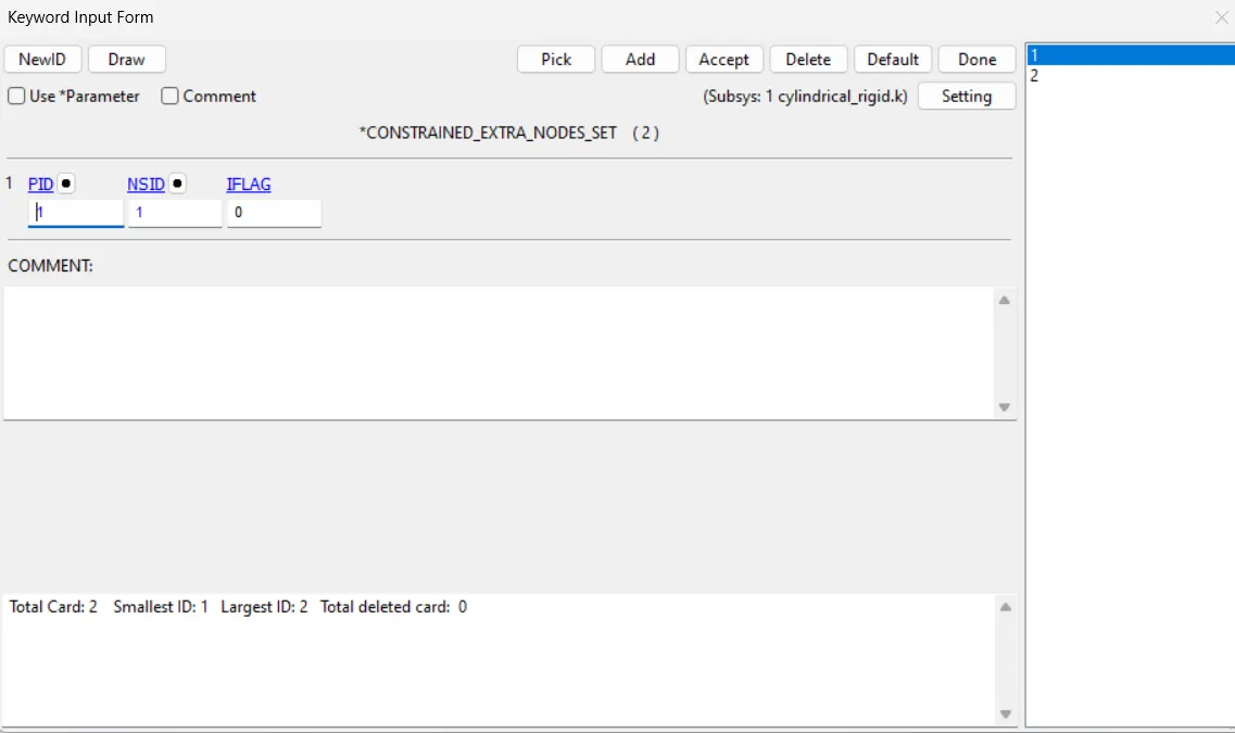
STEP 3: CREATING EXTRA NODES.
Two node pairs are created which are associated with each cylindrical shell.
STEP 4: DEFINE *CONSTRAINED_EXTRA_NODE_SET CARD.
STEP 5: USE JOINT CARD
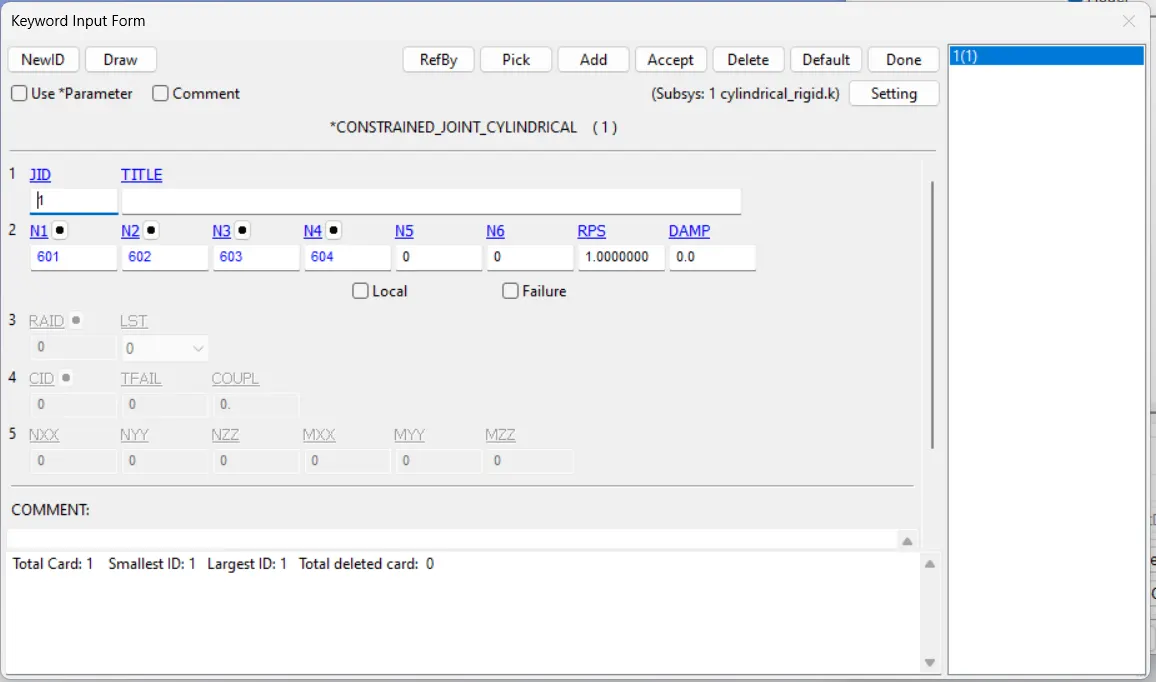
After that we have to give an initial velocity to inner cylinder, Control and Database cards are used in the cases repeated in the same manner for this type of joint as well.
THEN RUN THE FILE..............
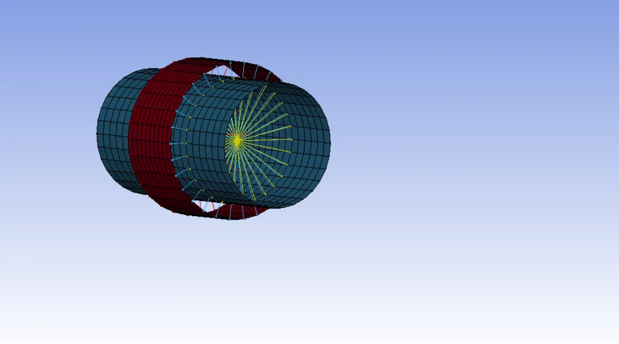
DEFORMABLE BODIES:
Here the only change is the CNRB's created with principle node pairs.
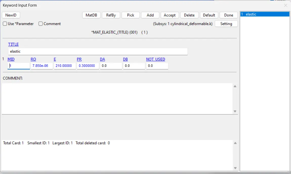
Then define the material card
Then, rest of the methods is repeated like done in earlier joints for rigid bodies.
THEN RUN THE FILE............
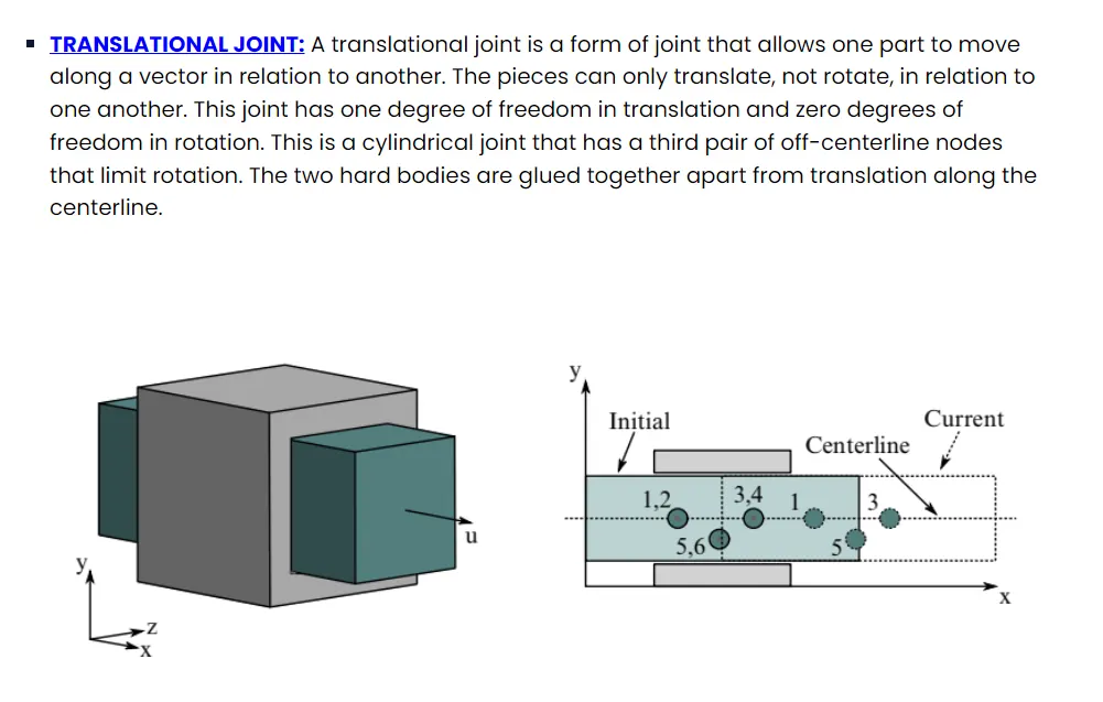
TRANSLATIOANL JOINT:
RIGID BODIES:
STEP 1: MAKE TWO SHELL BOXES
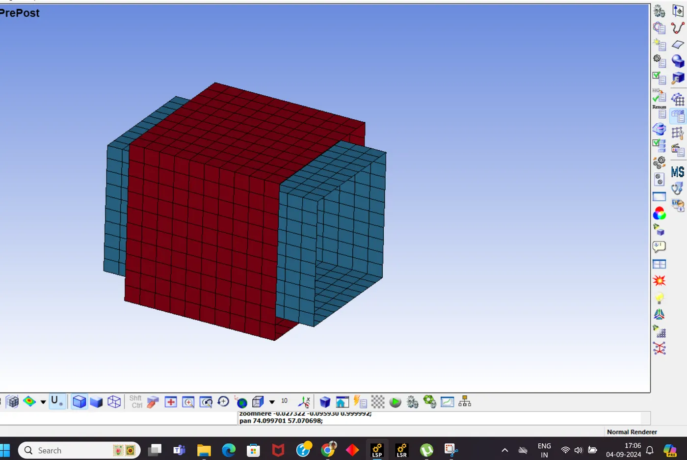
STEP 2: DEFINE MATERIAL
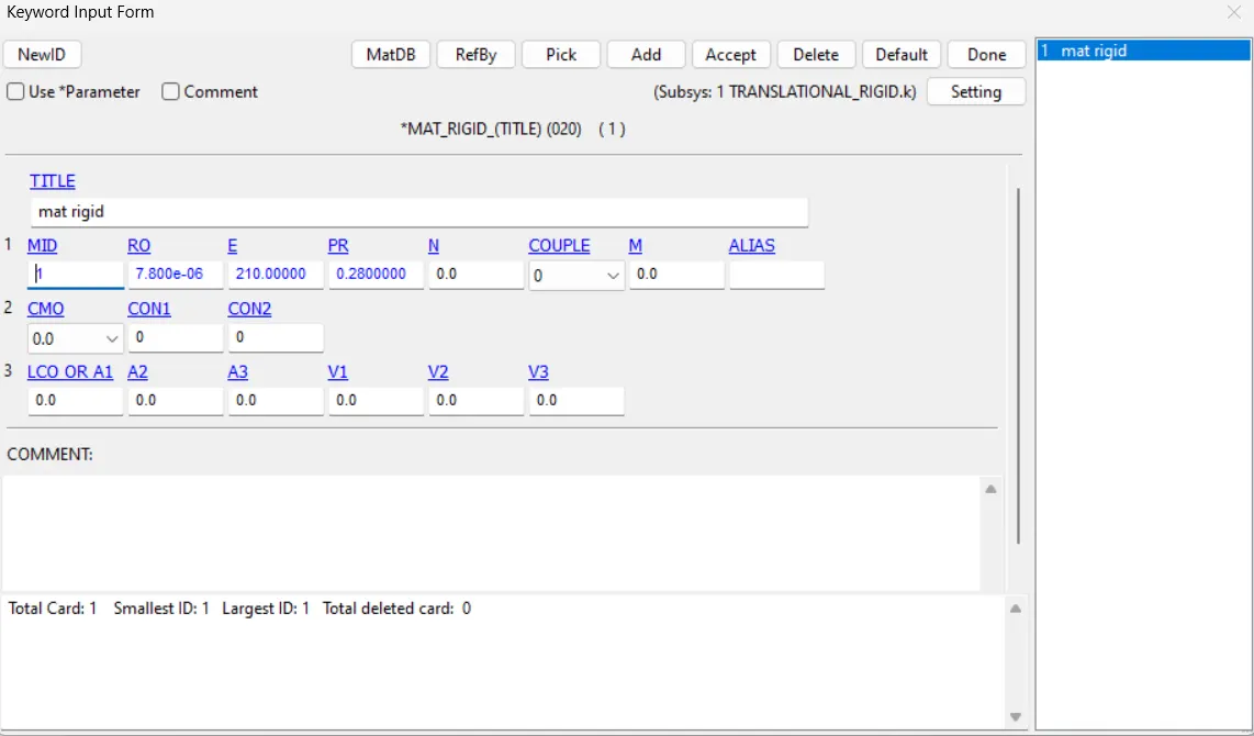
After that we have to define SECTION and PART
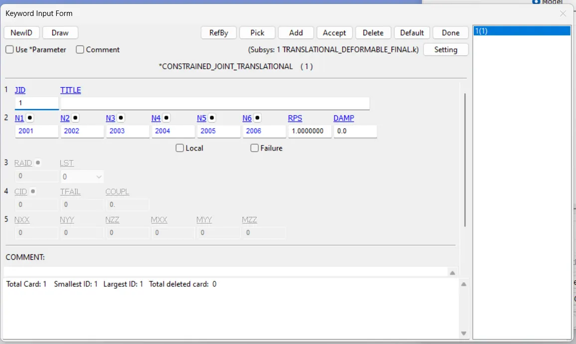
STEP 3: CREATION OF NODE PAIRS
The node pairs established here are obtained by following the instructions of the Translational joints in LS-DYNA manual Vol-1.
2001,2003,2005 nodes are associated with the outer box and 2002,2004,2006 nodes with inner box.
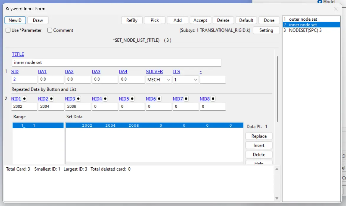
Then we have to define ,
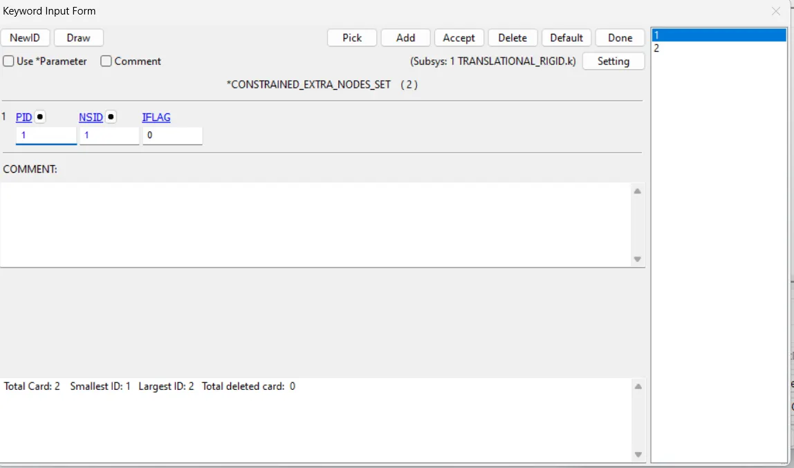
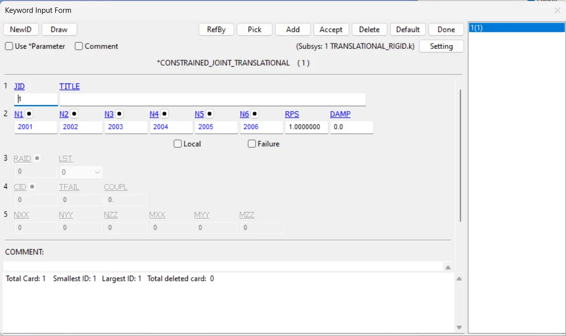
rest of the cards and methods are repeated.........
THEN RUN THE FILE.............
DEFORMABLE BODIES.
Here only two changes ,
1.MATERIAL
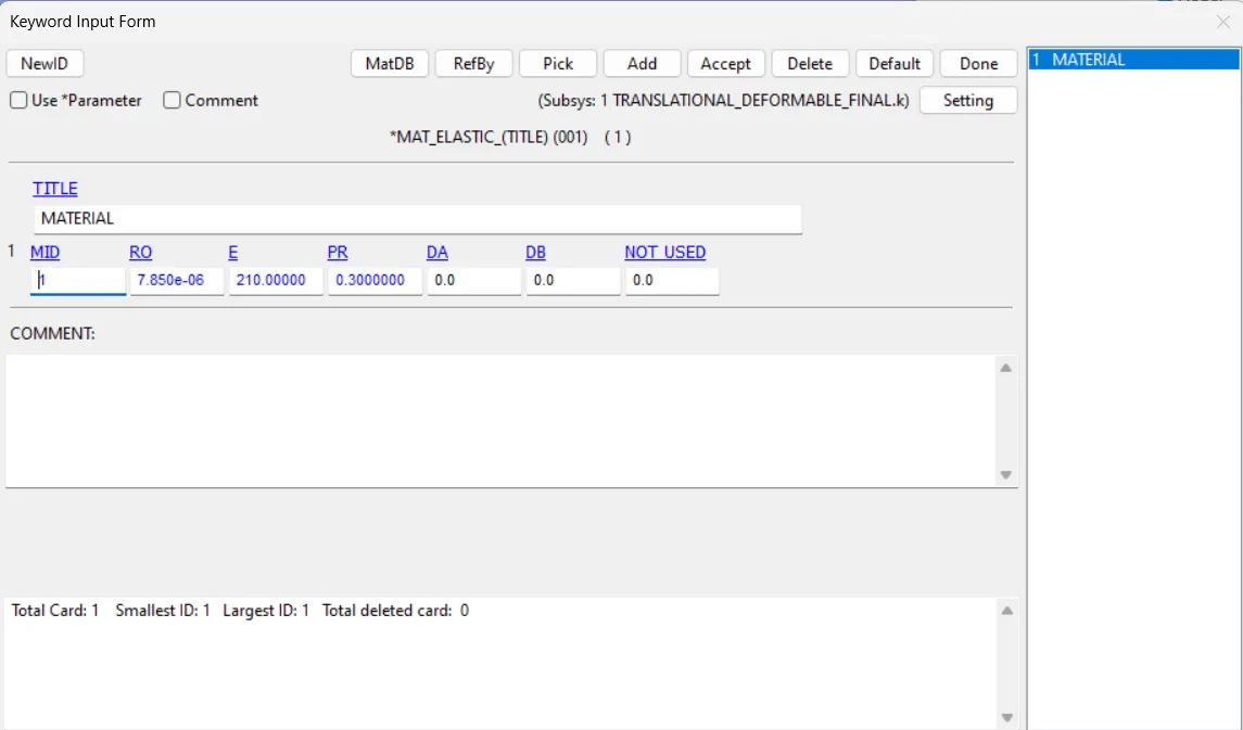
2 CREATING CNRB's.
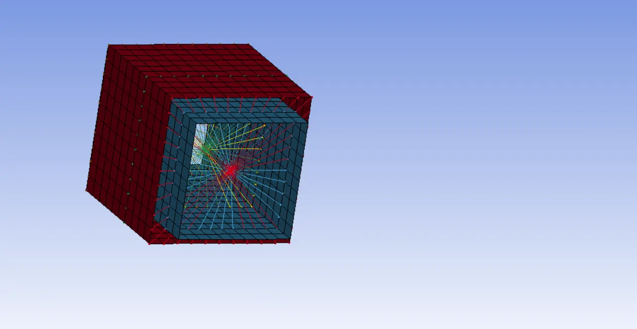
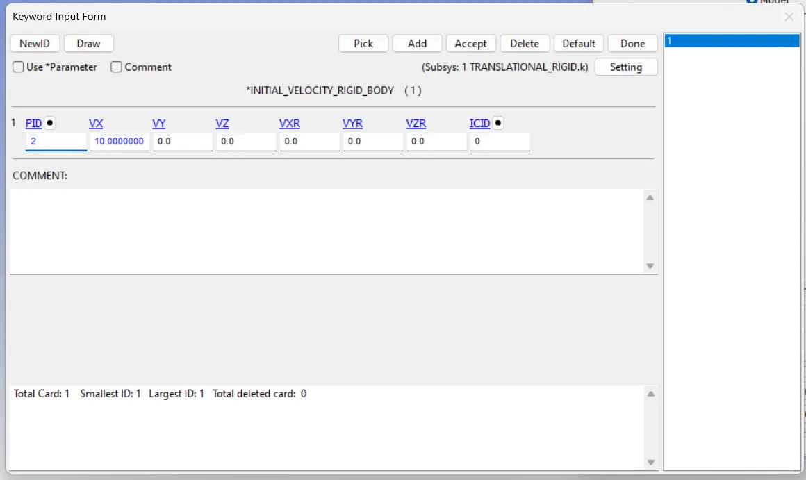
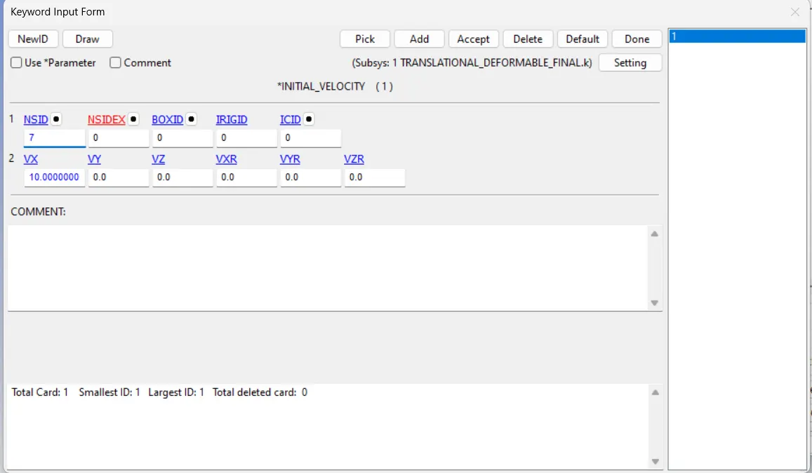
The initial velocity card and other mandatory cards are required to run the simulation are repeated most likely again.
THEN RUN THE FILE..........
=========================THANK YOU=================================