week-11 Joint creation and Demonstration
Joint creation and Demonstration
OBJECTIVE:
To demonstrate spherical, revolute, cylindrical, and translational joints between two rigid bodies and two deformable bodies with the help of Ls-Dyna manual (*CONSTRAINED_JOINT keyword).
SPHERICAL JOINT
PROCEDURE:
- A spherical rolling joint is a high-precision ball joint consisting of a spherical outer and inner race separated by ball bearings. The ball bearings are housed in a spherical retainer and roll along both the inner and outer surfaces. This design allows the joint to have very low friction while maintaining a large range of motion and backlash as low as 1 μm.
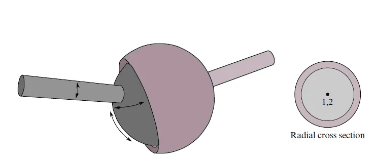
Fig.1.0. Spherical Joint
- The relative motion of the rigid bodies is constrained so that nodes which are initially coincident remain coincident. In the above figure the socket’s node is not interior to the socket—LS-DYNA does not require that a rigid body’s nodes be interior to the body.
 a
a
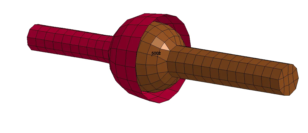
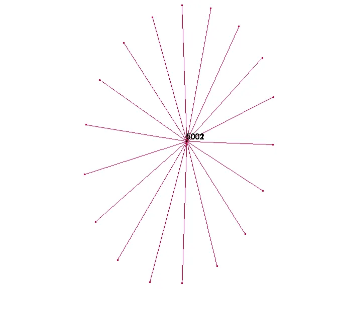
Fig. 1.1. Spherical Joint with nodal points 5001 and 5002 coinciding.
- The above figure shows the meshed model of Spherical joint. The cad is downloaded from grabcad.com and meshed in Hypermesh and the FE is imported into Ls-prepost
- Here the joint is created using CONSTRAINED_EXTRA_NODESET and CONSTRAINED_NODAL_RIGID_BODY.
- The socket is assigned with rigid material and the ball is assigned with steel material. Contrained_extra_nodeset is used to connect between rigid bodies and Contrained_nodal_rigid_body is used to connect between deformable bodies.
- At first, using create entity, CNRB connection is made by selecting the requied nodes on the ball part(deformable) and a PNODE at the middle of the sphere. The PNODE is then renumbered to a number which is easy to recollect to make it ease for the future use.
- The PNODE is then duplicated to so that the new duplicated node can be used for creating the Extra_node.
- It is then made sure that both the extra_node and the Pnode from CNRB are coinciding.
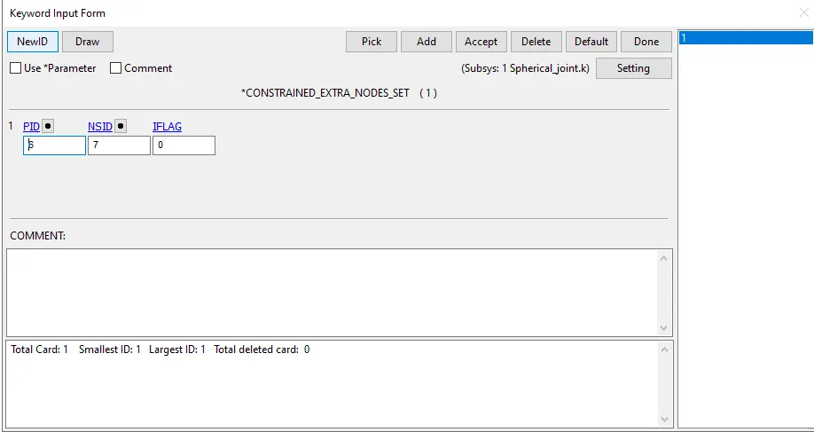
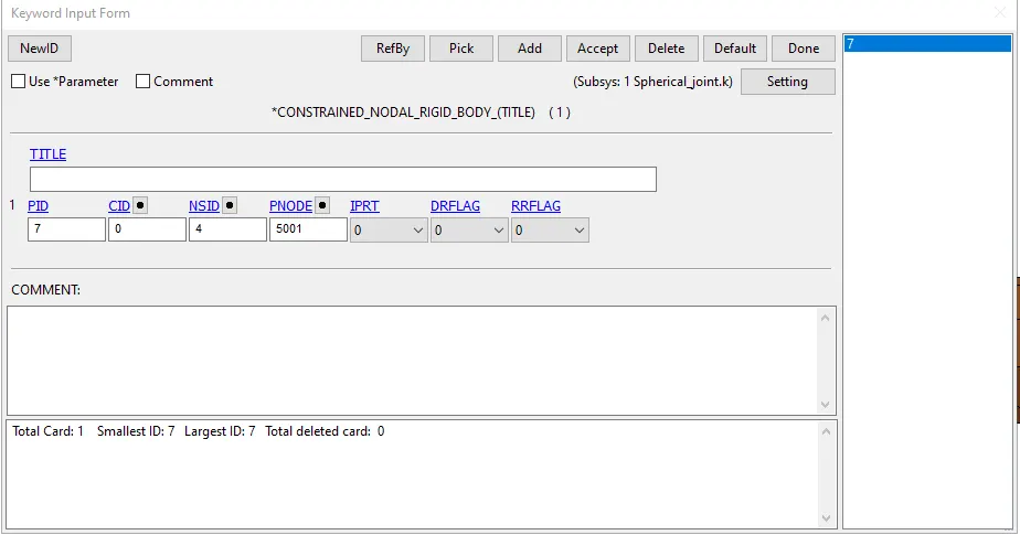
- CONSTRAINED_EXTRA_NODESET card consist of PID of the rigid body and NSID of all the node which is created for extra_node. CNRB card consist of NSID of all the node which is created for cnrb. PNODE is the node which is at the center of the cnrb web.
- Now the JOINT_SPHERICAL card is created where the nodes are define in an order.
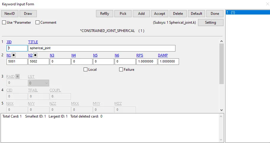
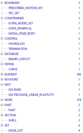
- The socket is constrained in global directions to make sure the simulation is stable. Boundary Prescribed Motion is defined on a few nodes at the end of the ball part to get the motion. for this a curve is also defined. Section shell is defined with 1mm thickness with element formulation as 16.
- All other procedures are similar to the pervious challenges and so it is not written here. The file is then saved and is ran in dyna manager and normal termination has occured.
RESULT:

- The above .gif file shows the simulation OUTPUT of Spherical joint which is created using CNRB and Extra_Node_Set.
REVOLUTE JOINT
PROCEDURE:
- A revolute joint (also called pin joint or hinge joint) is a one-degree-of-freedom kinematic pair used frequently in mechanisms and machines. The joint constrains the motion of two bodies to pure rotation along a common axis.
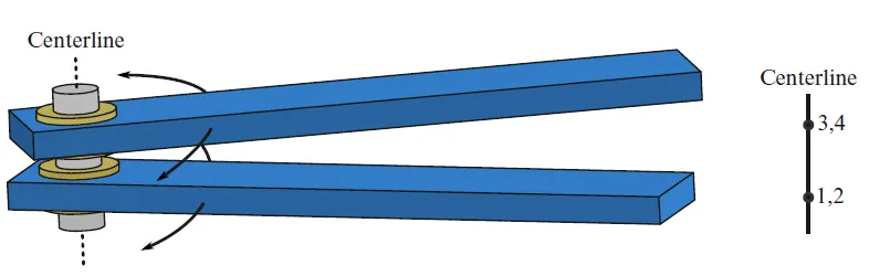
Fig. 1.2 Revolute Joint
- In Revolute Joint, Nodes 1 and 2 are coincident; nodes 3 and 4 are coincident. Nodes 1 and 3 belong to rigid body A; nodes 2 and 4 belong to rigid body B. The relative motion of the two rigid bodies is restricted to rotations about the axis formed by the two pairs of coincident nodes. This axis is labeled the “centerline”.
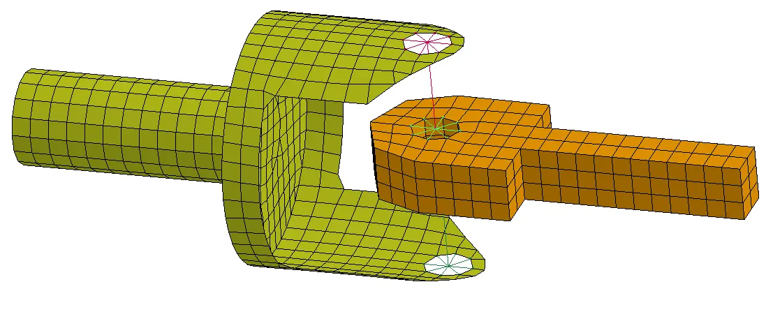
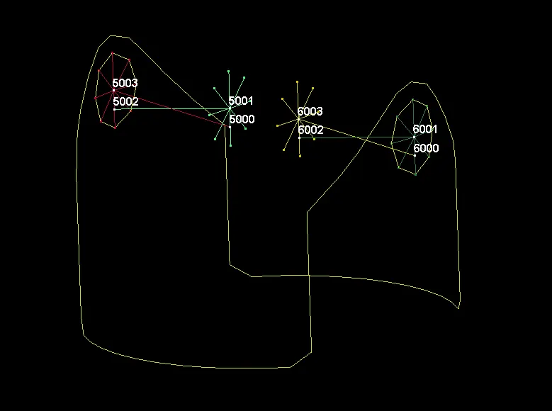
Fig.1.3. With nodes 6000,6001; 6002,6003 coinciding on one side and 5000,5001; 5002,5003 coincding on the other side.
- The above figure shows the meshed model of a Revolute joint. The cad is downloaded from grabcad.com and meshed in Hypermesh and the FE is imported into Ls-prepost
- Here the joint is created using CONSTRAINED_NODAL_RIGID_BODY alone.
- Both the parts are assigned with steel material (deformable) as CNRBs are used to connect between deformable bodies.
- At first, using create entity, CNRB connection is made by selecting the requied nodes as shown as in the above image.The nodes are then renumbered to numbers which is easy to recollect to make it ease for the future use.
- Then the nodes 6000,6001 ; 6002,6003 are made coincident on one side and nodes 5001,5001; 5002,5003 are made coincident on the other side.
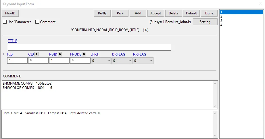
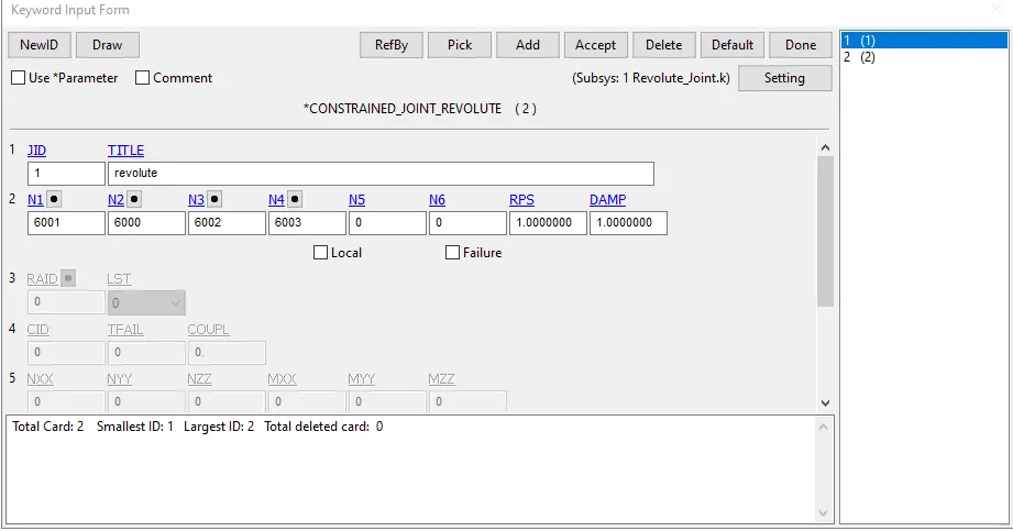
- CNRB card consist of NSID of all the node which is created for cnrb. PNODE is the node which is at the center of the cnrb web. 4 CNRBs are created here for the simulation
- Now the JOINT_REVOLUTE card is created where the nodes are define in an order.
- The yellow part is constained in global direction to make the simulation stable. Boundary prescribed motion is given to a few nodes at the end of orange part to get the motion.For this a curve is also defined. Section shell is defined with 1mm thickness with element formulation as 16.
- All other procedures are similar to the pervious challenges and so it is not written here. The file is then saved and is ran in dyna manager and normal termination has occured.
RESULT:
- The above .gif file shows the simulation OUTPUT of Revolute joint which is created using CNRB cards.
CYLINDRICAL JOINT
PROCEDURE:
- A cylindrical joint is a two-degree-of freedom kinematic pair used in mechanisms. Cylindrical joints provide single-axis sliding function as well as a single axis rotation, providing a way for two rigid bodies to translate and rotate freely. This can be pictured by an unsecured axle mounted on a chassis, as it may freely rotate and translate. An example of this would be the rotating rods of a Table Football.
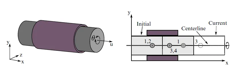
- This joint is derived from the rotational joint by relaxing the constraints along the centerline. This joint admits relative rotation and translation along the centerline.
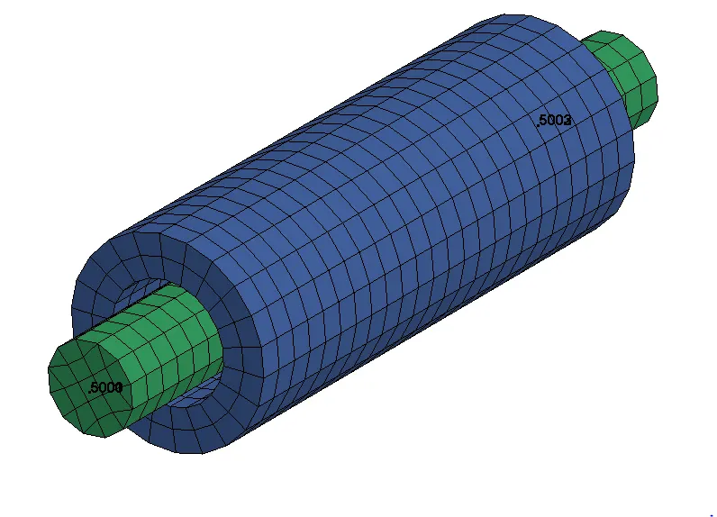
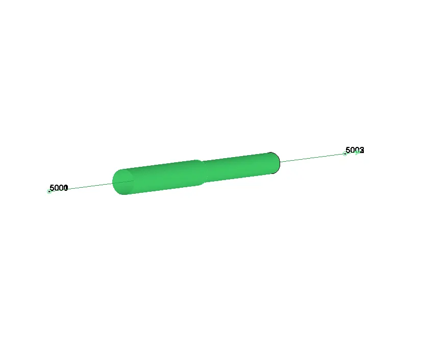
Fig.1.4. Cylindrical joint With nodes 5000,5001; 5002,5003 coinciding.
- The above figure shows the meshed model of a Cylindrical joint. The FE is meshed in Hypermesh and it is then imported into Ls-prepost
- Here the joint is created using CONSTRAINED_EXTRA_NODES alone.
- Both the parts are assigned with rigid material as extra node set are used to connect between rigid bodies.
- At first, using node edit option, nodes are created at the middle of the holes which are required to create the extra nodes.The nodes are then renumbered to numbers which is easy to recollect to make it ease for the future use.
- Then the nodes 5000,5001 ; 5002,5003 are made coincident.
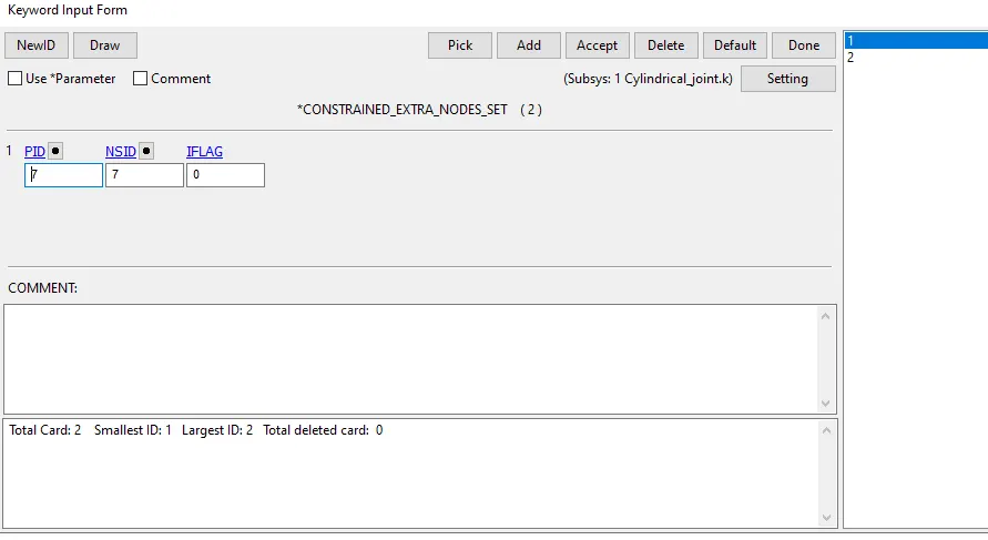
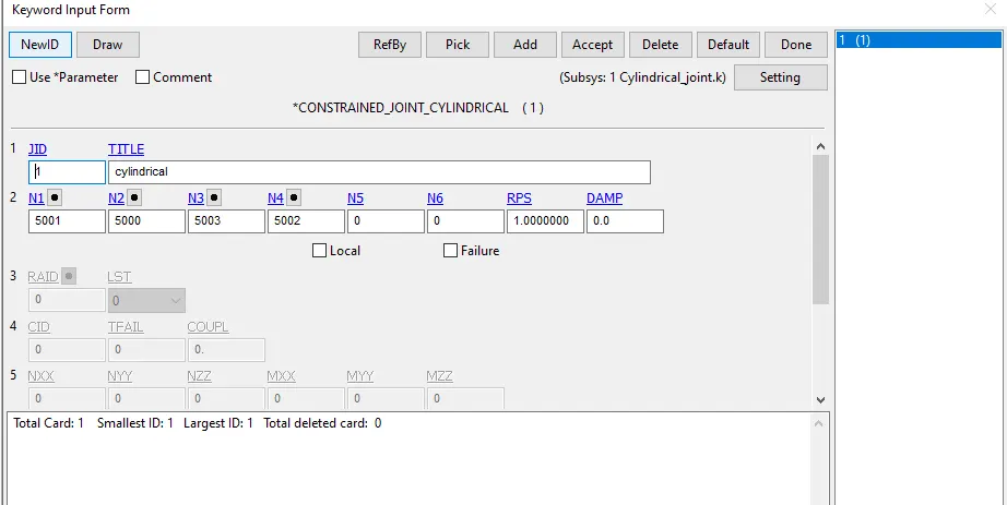
- Like discussed in the procedures of joint,CONSTRAINED_EXTRA_NODESET card consist of PID of the rigid body and NSID of all the node which is created for extra_node.
- Contrained_Joint_Cylindrical card is then created and the nodes are given in the particular order.
- The Outer cylinder is constrained in global directions to make the simulation stable and Velocity_Rigid_Body card is assigned to the shaft for the initial velocity. here 3mm/ms velocity is given to it in the +ve X direction. Rotaion is also defined in the model.
- Solid section with ELFORM as 1 is used here for the simulation.
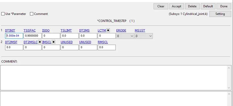
- CONTROL_TIMESTEP card is also defined for some joints where the timestep is not stable.
- All other procedures are similar to the pervious challenges and so it is not written here. The file is then saved and is ran in dyna manager and normal termination has occured.
RESULT:
- The above .gif file shows the simulation OUTPUT of Cylindrical joint which is created using Extra_nodes cards.
TRANSLATIONAL JOINT
PROCEDURE
- A translational joint allows one part to translate along a vector in respect of another part. The parts can only translate, not rotate, in respect of each other. ... The direction of the motion of the translational joint is parallel to the orientation vector and passes through the location.
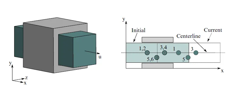
Fig 1.6 Translational Joint
- This is a cylindrical joint with a third pair of off-centerline nodes which restrict rotation. Aside from translation along the centerline, the two rigid bodies are stuck together.
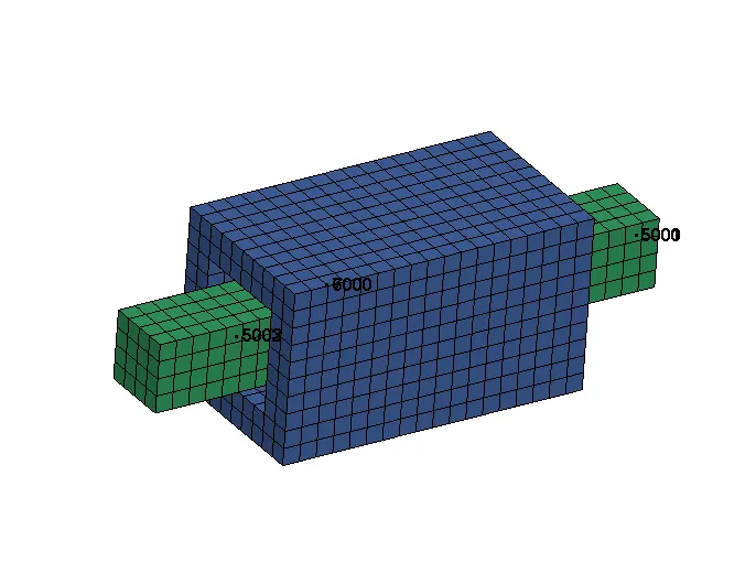
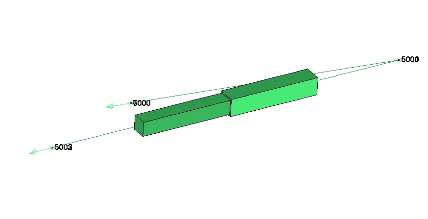
Fig.1.7. Cylindrical joint With nodes 5000,5001; 5002,5003;6000,7000 coinciding.
- The above figure shows the meshed model of a Translational joint. The FE is meshed in Hypermesh and it is then imported into Ls-prepost
- Here the joint is created using CONSTRAINED_EXTRA_NODES alone.
- Both the parts are assigned with rigid material as extra node set are used to connect between rigid bodies.
- At first, using node edit option, nodes are created at the middle of the holes which are required to create the extra nodes.The nodes are then renumbered to numbers which is easy to recollect to make it ease for the future use.
- unlike in cylindrical joint, here a third pair of off-centerline nodes are present which restrict rotation and so we do have only 1 D.O.F here.
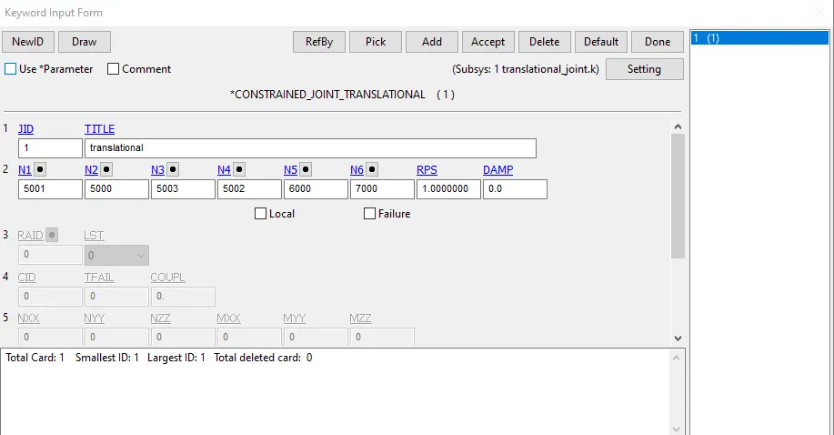
- Then the nodes 5000,5001 ; 5002,5003;6000,7000 are made coincident.
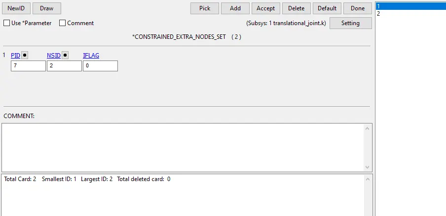
- Like discussed in the procedures of joint,CONSTRAINED_EXTRA_NODESET card consist of PID of the rigid body and NSID of all the node which is created for extra_node.
- Contrained_Joint_Translational card is then created and the nodes are given in the particular order.
- The Outer part is constrained in global directions to make the simulation stable and Velocity_Rigid_Body card is assigned to the inner part for the initial velocity. here 5mm/ms velocity is given to it in the +ve Z direction.
- Solid section with ELFORM as 1 is used here for the simulation.
- CONTROL_TIMESTEP card is also defined for some joints where the timestep is not stable.
- All other procedures are similar to the pervious challenges and so it is not written here. The file is then saved and is ran in dyna manager and normal termination has occured.
RESULT:
- The above .gif file shows the simulation OUTPUT of Translational joint which is created using Extra_nodes cards.
CONCLUSION:
All the joints, Spherical, Revolute, Cylindrical, and Translational joints between two rigid bodies and two deformable bodies are demonsrated with the help of Ls-Dyna manual (*CONSTRAINED_JOINT keyword,).
Note: All the necessary files are attached with this report.
Thanks:)