week-11 Joint creation and Demonstration
AIM:
To create the different kinds of joints like the spherical, revolute, cylindrical, and translational joints.To use *CONSTRAINED_EXTRA_NODES and *CONSTRAINED_NODAL_RIGID_BODY to create joints between rigid and deformable bodies respectively.
MECHANICAL JOINTS:
1) Revolute joint -
A revolute joint is a 1 DOF kinematic pair. It constrains the motion of two bodies to pure rotation along a common axis. The joint doesn't allow translation, or sliding linear motion.
2) Spherical joint -
A Spherical joint is also called as ball-socket joint. It is a 3 DOF kinematic pair allowing rotation along 3 axes.
3) Translational joint -
A translational joint is also called as prismatic joint. It is a 1 DOF kinematic pair. It allows translation along the common axis.
4) Cylindrical joint -
A cylindrical joint is a 2 DOF kinematic pair. Cylindrical joints provide single-axis sliding function as well as a single axis rotation, providing a way for two rigid bodies to translate and rotate freely.
PROCEDURE:
In Ls-Dyna, different types of joints are modeled. In this report, joints are made between two rigid bodies and two deformable bodies.
1) Revolute joint Rigid Bodies :
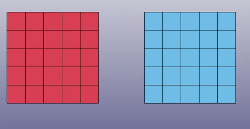
Create two plates of dimension 80X80
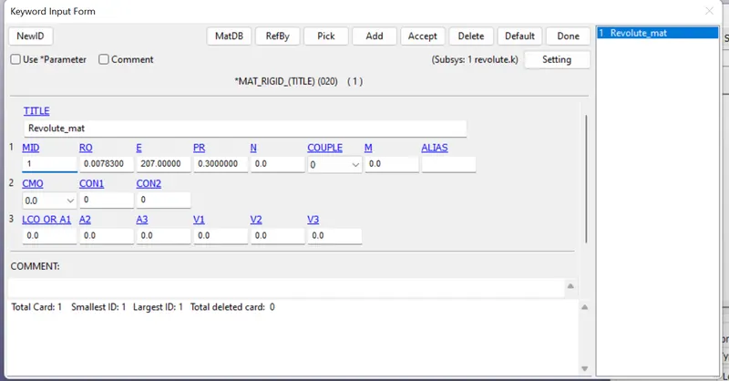
Create rigid material card
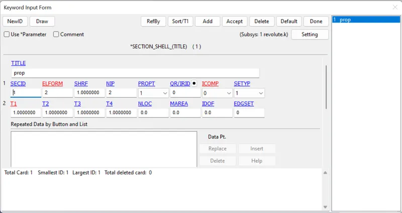
Section shell keycard, of plate thickness 1mm
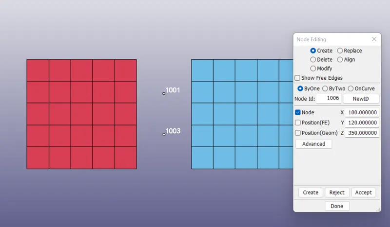
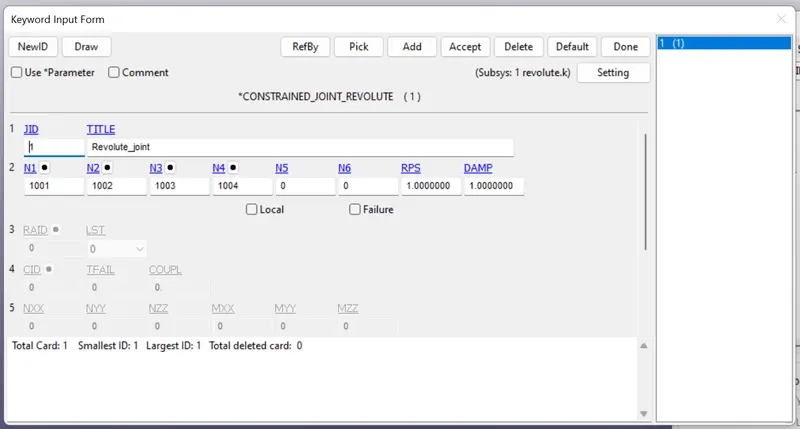
To create revolute joint, for each body two nodes are created. In the following fig, nodes 1,3 represents nodes for body 1 and nodes 2,4 represents nodes for body2. Node 1 coincides with node 2 and node 3 coincides with node 4. The line passing trough these 4 nodes represents axis of rotation.
Create nodes by ELEMENT TOOLS -> NODE EDITING as shown in the fig. Similary create 3 more nodes.
Include the created nodes 101, 103 in PID 1 and nodes 102, 104 in PID 2 by using CONSTRAINED_EXTRA_NODE_SET keycard.
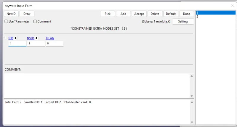
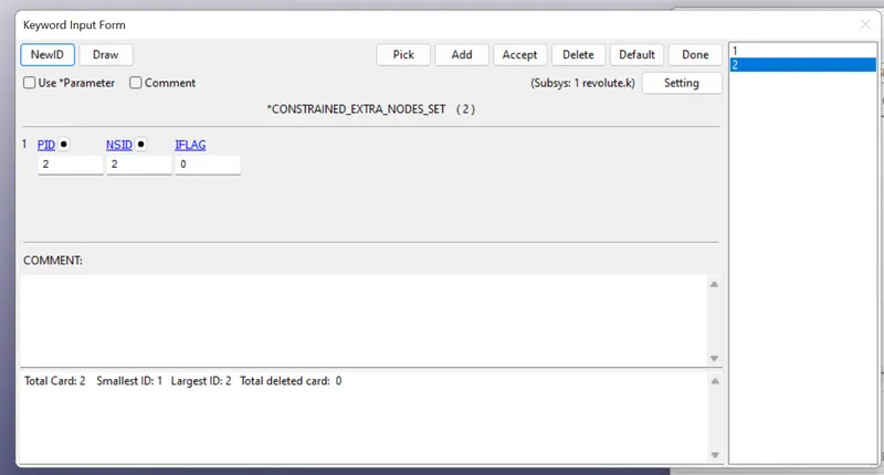
A CONSTRAINED_JOINT_REVOLUTE keycard is used to create a revolute joint.
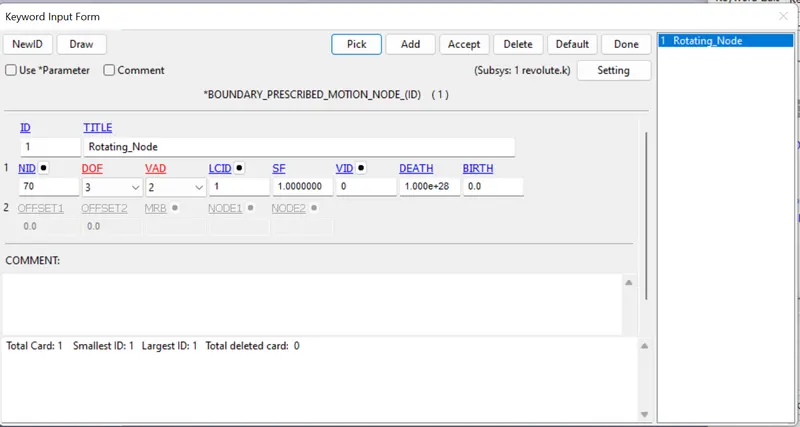
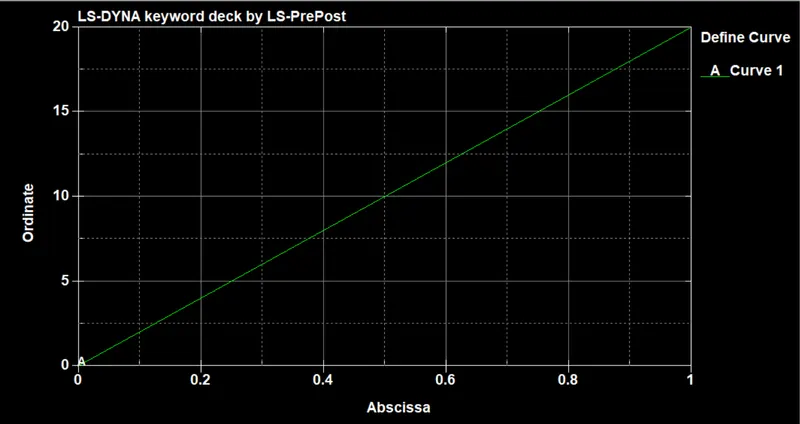
Initial conditions are given to node 70 in the form of displacement curve as shown in the fig.
Initial time step is given as 0.1
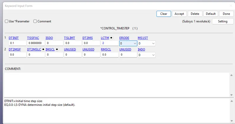
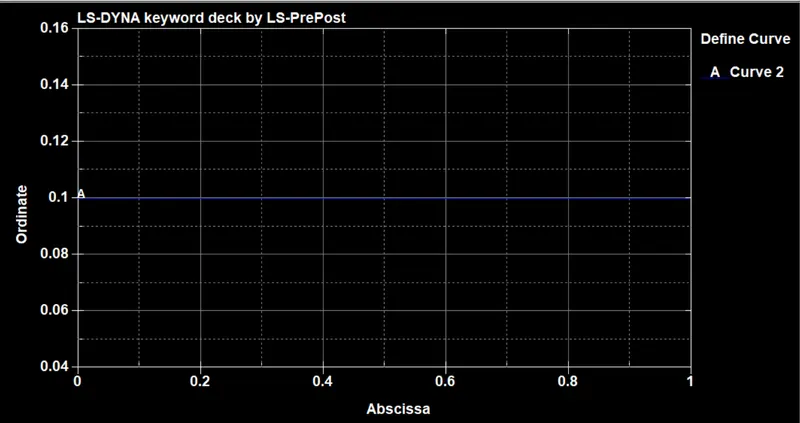
LCTM:
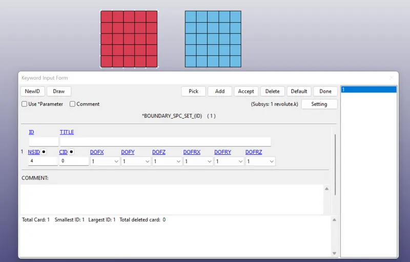
As the Displacement Is Given to the Nodes from Part-2, part-1 Is constrained In all DoF's
Control-cards:-
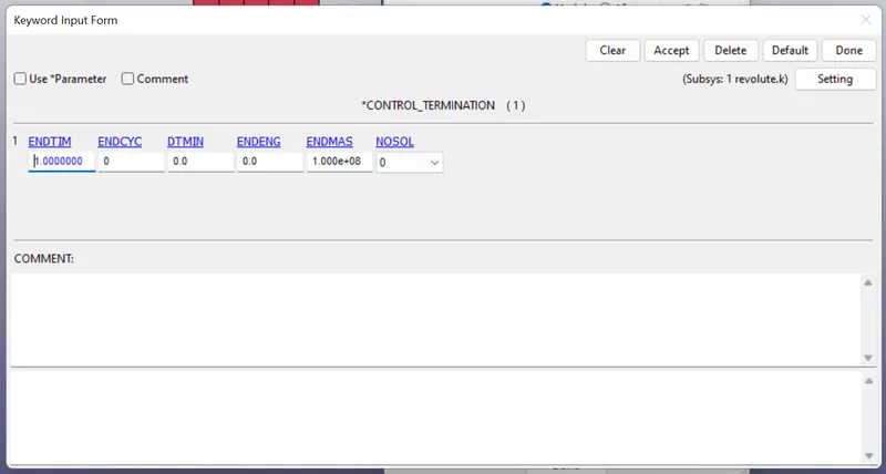
Control cards Such as Control Termination and time step.
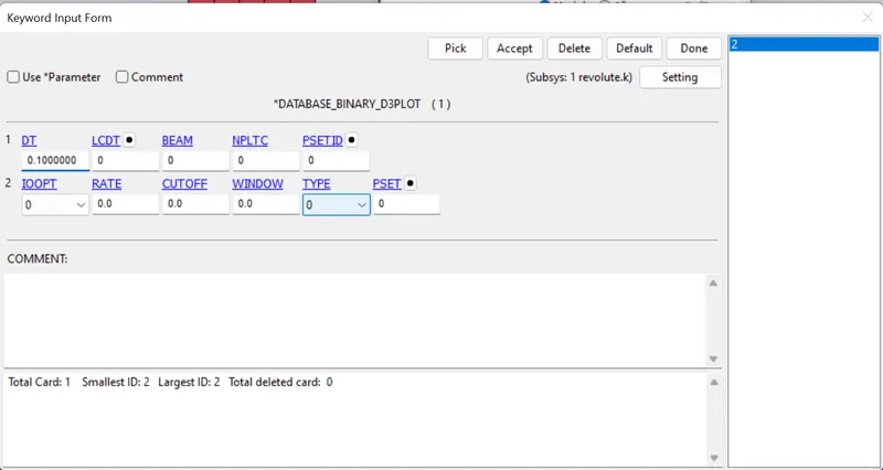
Database Binary D3Plot is defined To print the Results at 0.1ms in each interval
SPHERICAL JOINT:
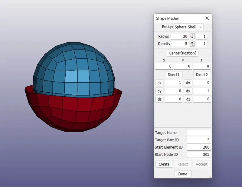
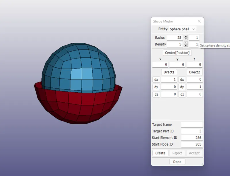
First, we need to create two spheres shell mesh with different radius. Go to LS-Prepost >mesh>shaper>sphere shell. Here we need to create two spheres with different radius. Now delete half of the elements using element tool>element edit. Now we have one hemisphere, a sphere.
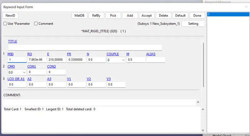
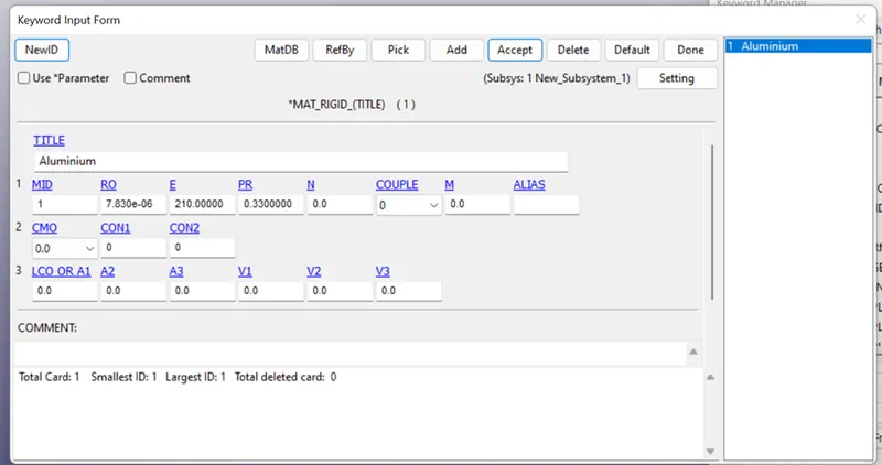
Now define a material card for the parts. Go to model&keywords>all>MAT>MAT_RIGID. here define density, young's modulus, Poisson's ratio. Now apply and done.
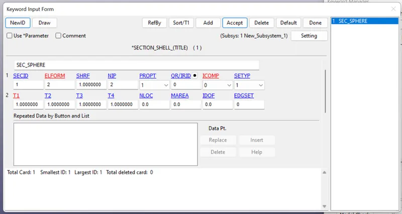
Define section id for the part. Go to model&keywords>all>Section>shell. Here define parameters. Now accept and done.
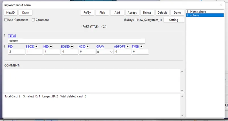
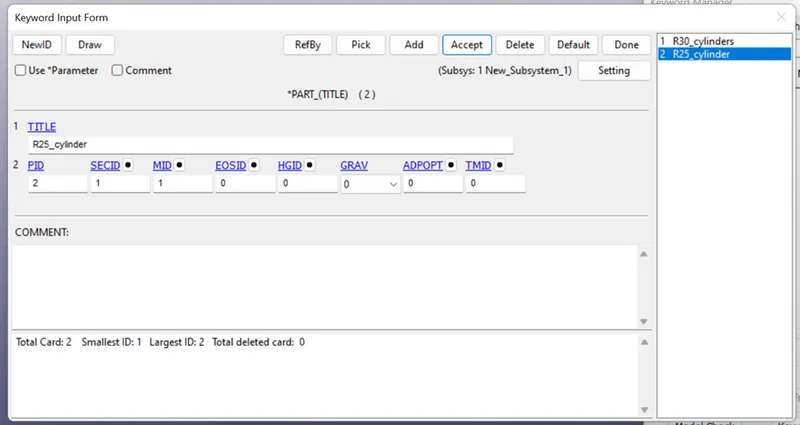
Define section and MAT id for the part using model&keywords>all>part. Now assign the sec and mat id.
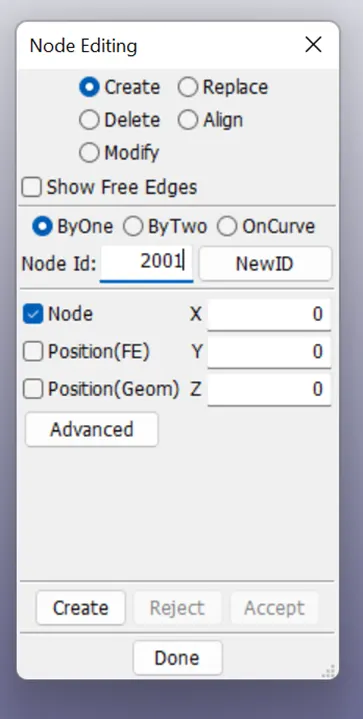
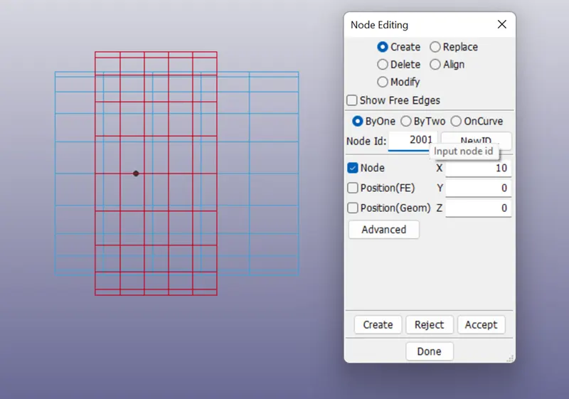
Now create two nodes for the two parts. Node 1 is assigned for part 1(2001) and node 2 for part 2(2002). it will be created in the same coordinates. For creating nodes, go to element tools>node edit>create.
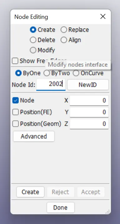
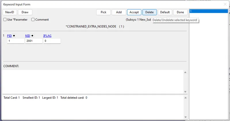
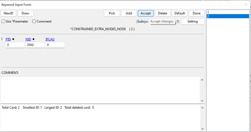
Now create constrained_extra_nodes_node card using model&keywords>all>Constrained. Now assign the first node (2001) for part 1 and the second node (2002) for part 2.
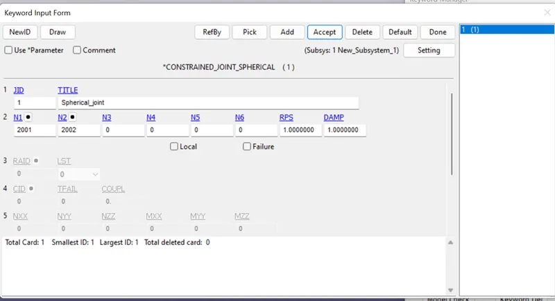
Now create constrained_join_spherical card using model&keywords>all>Constrained. Here we need to assign nodes for the respective parts. N1 for part 1and N2 for part 2. assign the values as per the parameters.
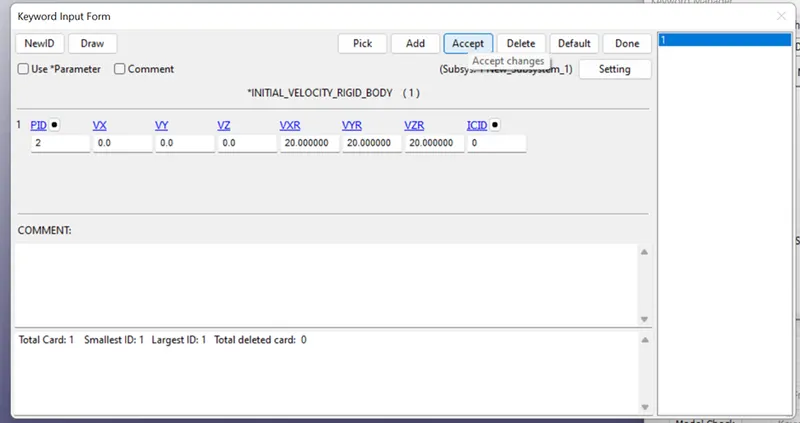
Now define initial_velocity_rigid_body card using model&keywords>all>initial. Define part id and X,Y,Z rotational values as 20mm/ms.
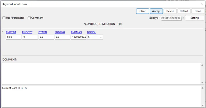
Now define the control card for the simulation. define control termination card in model&keywords>all>control. Now put end time as 50ms.
Define binary d3plot for output animation file. go to model&keywords>all>database>binary d3plot. Here assign DT value as 0.1.
CYLINDERICAL JOINT:
First, we need to create two cylinders of shell mesh with different radius and lengths. Go to LS-Prepost >mesh>shaper>cylinder shell. Here we need to create two spheres with different radius and lengths. Now delete the elements of the side face using element tool>element edit. Now we have two cylinders.
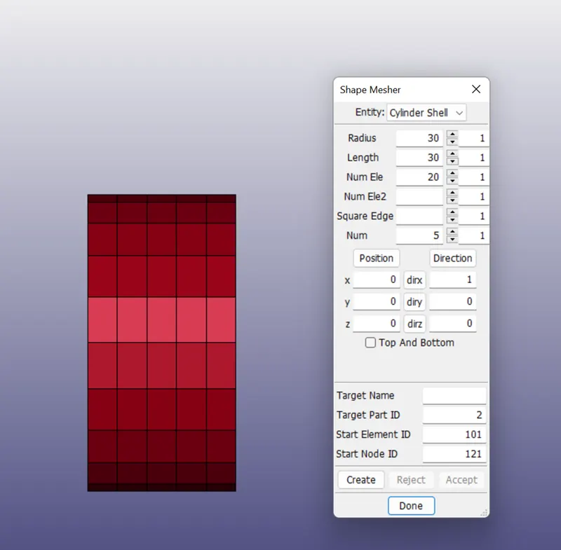
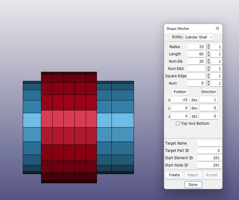
Now define a material card for the parts. Go to model&keywords>all>MAT>MAT_RIGID. here define density, young's modulus, Poisson's ratio. Now apply and done.
Define section id for the part. Go to model&keywords>all>Section>shell. Here define parameters. Now accept and done.
Translational joints:
Define section and MAT id for the part using model&keywords>all>part. Now assign the sec and mat id.
Now create four nodes for the two parts. Node 1&2 is assigned for part 1(2001,2002) and node 2&4 for part 2(2003,2004). it should be in coincidence and collinear. For creating nodes, go to element tools>node edit>create.
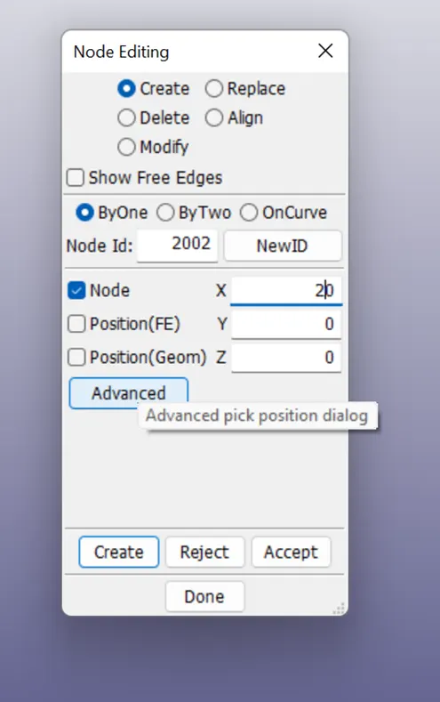
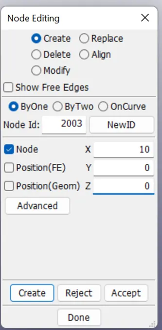
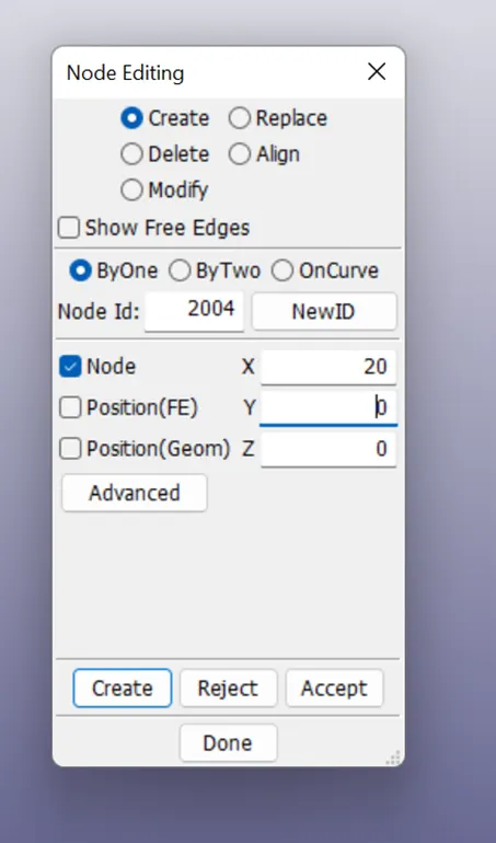
Now Go to model&keywords>create entity>set_node. here we need to create a node-set for constrained nodes. 2001 and 2002 nodes as one node set for part 1 and 2003, 2004 as the second node set for part 2.
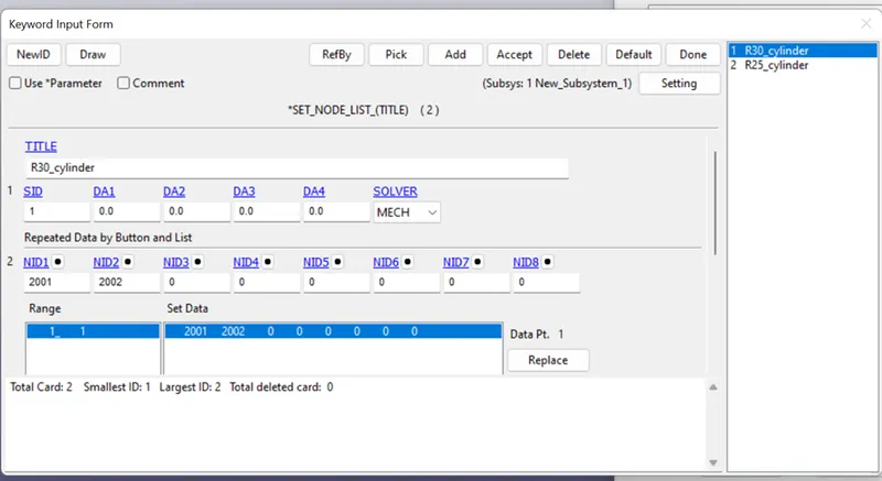
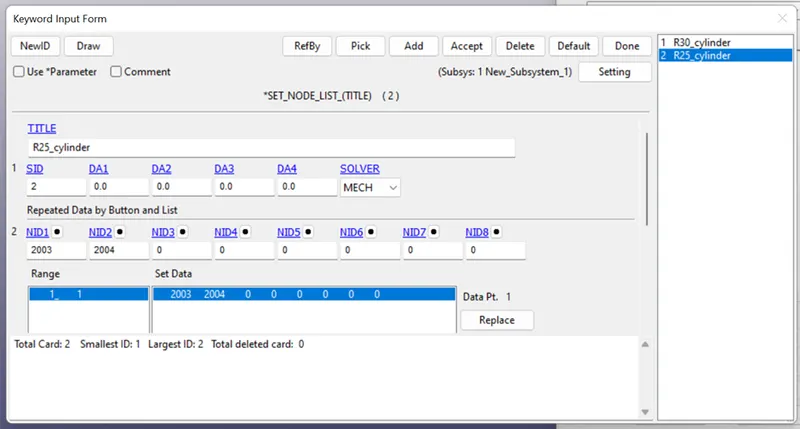
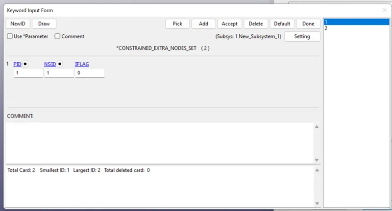
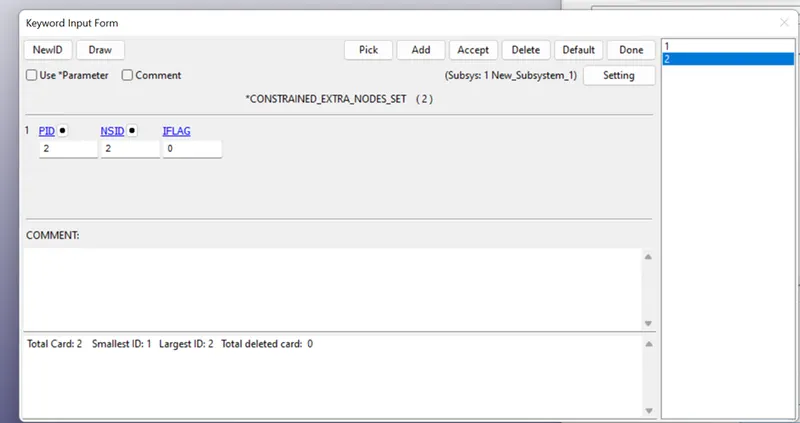
Now create constrained_extra_nodes_set card using model&keywords>all>Constrained. Now assign the first node-set(2001&2002) for part 1 and the second node-set (2003&2004) for part 2.
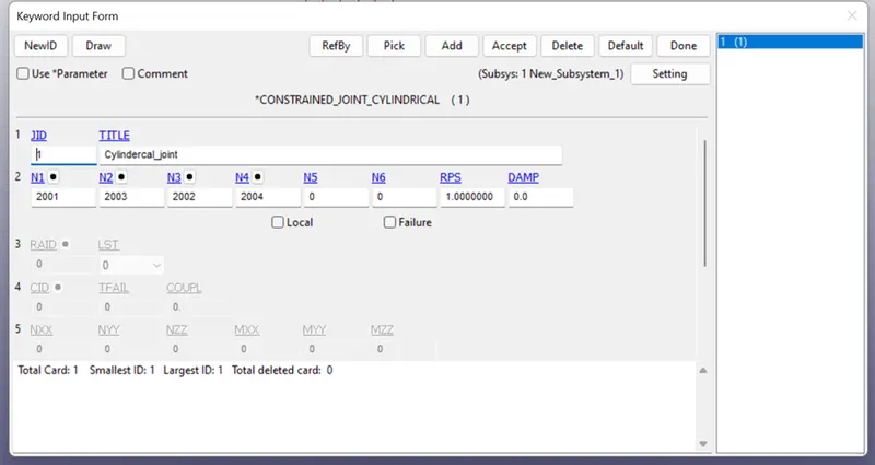
Now create constrained_join_cylinderical card using model&keywords>all>Constrained. Here we need to assign nodes for the respective parts. N1&N3 for part 1and N2&N4 for part 2. assign the values as per the parameters.
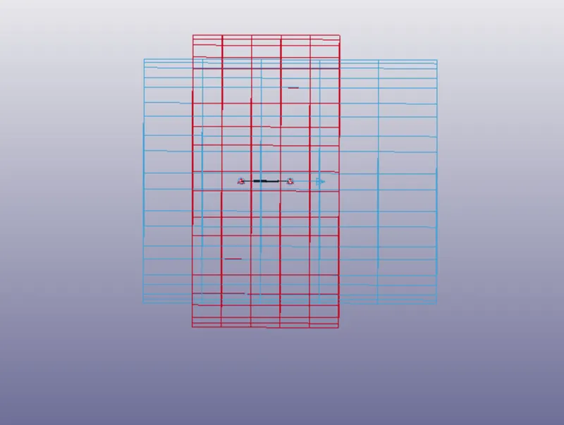
Now define initial_velocity_rigid_body card using model&keywords>all>initial. Define part id and X axis translational as 10mm/ms. the translational only at x-axis.
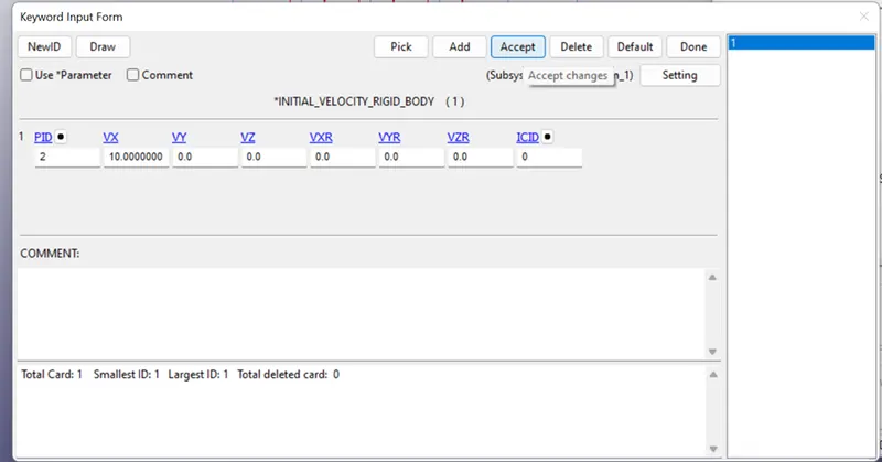
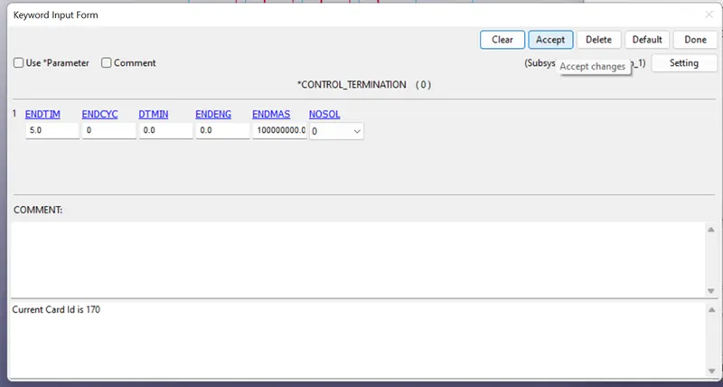
Now define the control card for the simulation. define control termination card in model&keywords>all>control. Now put end time as 5ms.
Define binary d3plot for output animation file. go to model&keywords>all>database>binary d3plot. Here assign DT value as 0.1.
Joints between deformable bodies:
Here we should create joints between deformable bodies but we can follow the same steps of joints between rigid bodies for defining joints between deformable bodies with some few changes.
- Instead of using MAT_RIGID, we should use MAT_ELASTIC card for defining material card for the parts.
- Instead of using constrained_extra_nodes, constrained_nodal_rigid_body(CNRB) is used to constrain the nodes for the respective parts.
- Instead of using initial_velocity_rigid_body, Initial_velocity is used to define velocity for the part.
Revolute joint:
Follow the same procedure of revolute rigid joints for creating and assigning section, parts, material cards of the parts.
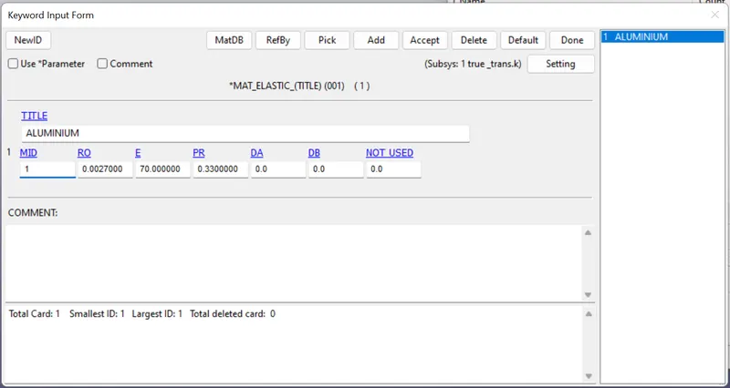
Here define material card MAT_ELASTIC, go to model&keywords>all>MAT>MAT_ELASTIC. define parameters in the tab. now accept and done.
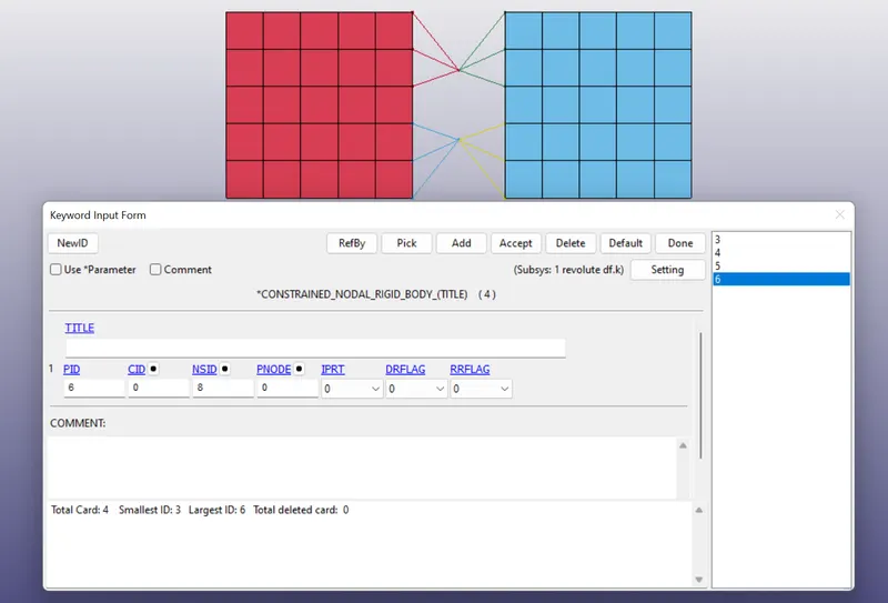
Now create constrained_nodal_rigid_body using create entity>constrained>CNRB. Now uncheck PNode option. Now select node 1001 and neighbor nodes for creating CNRB. NOw follow the same steps for creating CNRB at 1002,1003,1004 nodes.
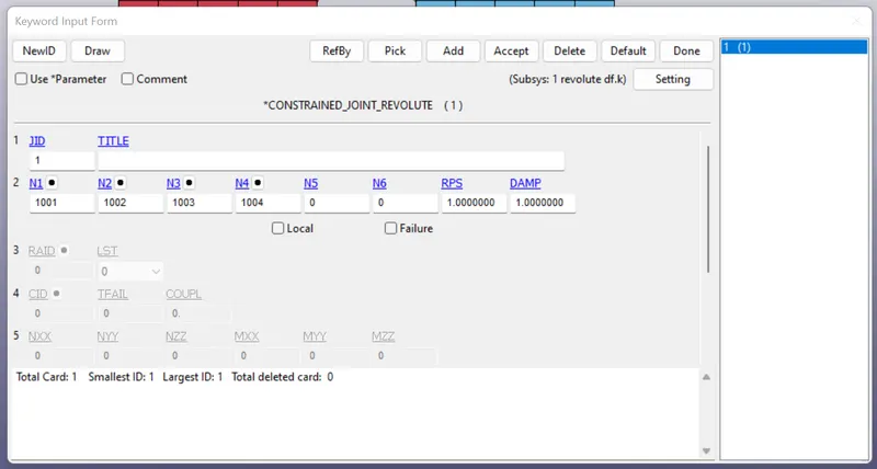
Now create constrained_join_revolute card using model&keywords>all>Constrained. Here we need to assign nodes for the respective parts. N1, N3 for part 1 and N2, N4 for part 2. assign the values as per the parameters.
This is defined by boundary_prescribed_motion_node card using model&keywords>all>boundary.
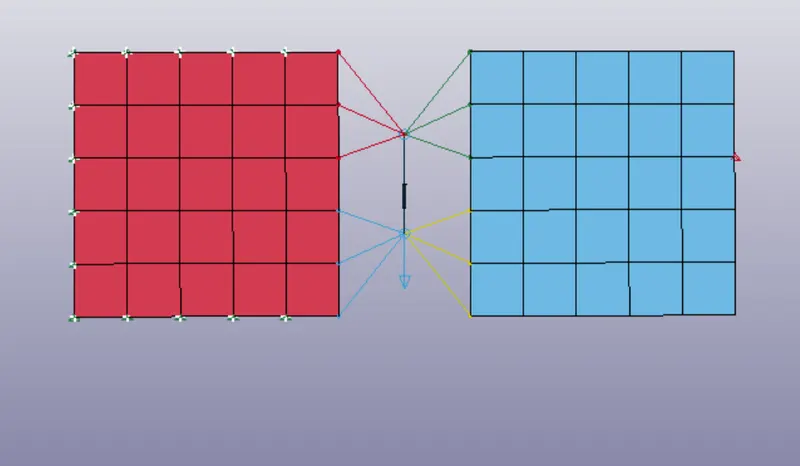
Now we need to fix part 1 for that define boundary_spc card
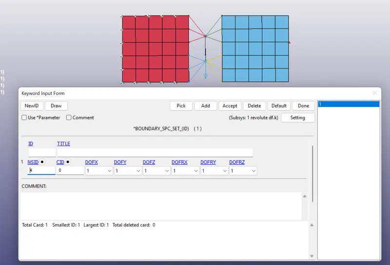
using model&keywords>all>boundary. here assign the nodes in the edges of part-1. Now part 1 is fixed.
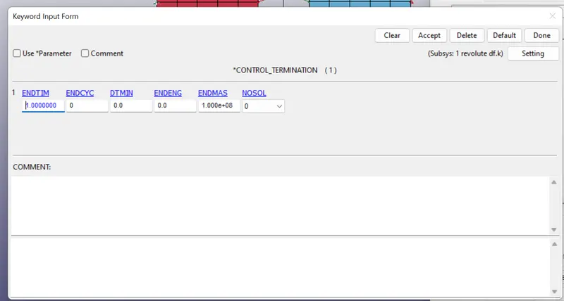
Now define the control card for the simulation. define control termination card in model&keywords>all>control. Now put end time as 1ms.
Define binary d3plot for output animation file. go to model&keywords>all>database>binary d3plot. Here assign DT value as 0.1.
Spherical joint:
Here follow the same procedure of spherical rigid joints for creating and assigning sections, parts, material cards of the parts.
Here define material card MAT_ELASTIC, go to model&keywords>all>MAT>MAT_ELASTIC. define parameters in the tab. now accept and done.
Now create constrained_nodal_rigid_body using create entity>constrained>CNRB. Now uncheck PNode option. Now select node 2001 and neighbour nodes for creating CNRB. NOw follow the same steps for creating CNRB at 2002 node.
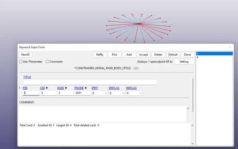
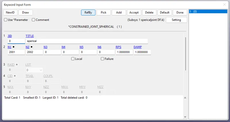
Now create constrained_join_spherical card using model&keywords>all>Constrained. Here we need to assign nodes for the respective parts. N1 for part 1and N2 for part 2. assign the values as per the parameters.
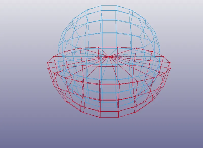
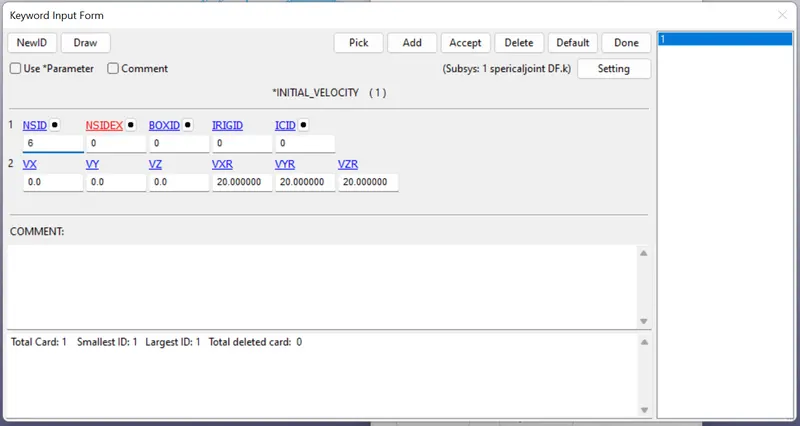
Now define initial_velocity card using model&keywords>all>initial. Define part id and X,Y,Z rotational values as 20mm/ms.
Now define the control card for the simulation. define control termination card in model&keywords>all>control. Now put end time as 20ms.
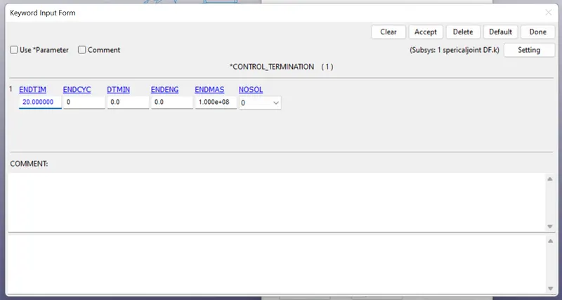
Define binary d3plot for output animation file. go to model&keywords>all>database>binary d3plot. Here assign DT value as 0.1.
Cylindrical joint:
Here follow the same procedure of cylindrical rigid joints for creating and assigning section, parts, material cards of the parts.
Here define material card MAT_ELASTIC, go to model&keywords>all>MAT>MAT_ELASTIC. define parameters in the tab. now accept and done.
Now create constrained_nodal_rigid_body using create entity>constrained>CNRB. Now uncheck PNode option. Now select node 2001 and neighbour nodes for creating CNRB. NOw follow the same steps for creating CNRB at 2002,2003,2004 nodes.
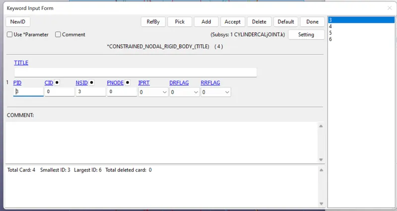
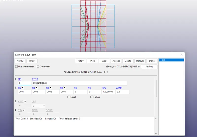
Now create constrained_join_cylinderical card using model&keywords>all>Constrained. Here we need to assign nodes for the respective parts. N1&N3 for part 1and N2&N4 for part 2. assign the values as per the parameters.
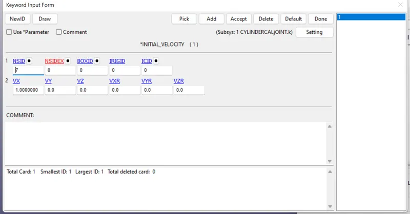
Now define initial_velocity card using model&keywords>all>initial. Define part id and X axis translational as 1mm/ms. the translational only at x-axis.
Now define the control card for the simulation. define control termination card in model&keywords>all>control. Now put end time as 10ms.
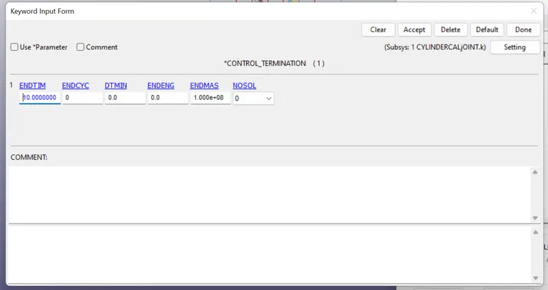
Define binary d3plot for output animation file. go to model&keywords>all>database>binary d3plot. Here assign DT value as 0.1.
Translational joint:
Here follow the same procedure of translational rigid joints for creating and assigning section, parts, material cards of the parts.
Here define material card MAT_ELASTIC, go to model&keywords>all>MAT>MAT_ELASTIC. define parameters in the tab. now accept and done.
Now create constrained_nodal_rigid_body using create entity>constrained>CNRB. Now uncheck PNode option. Now select node 5001 and neighbour nodes for creating CNRB. NOw follow the same steps for creating CNRB at 5002,5003,5004,5005,5006 nodes.
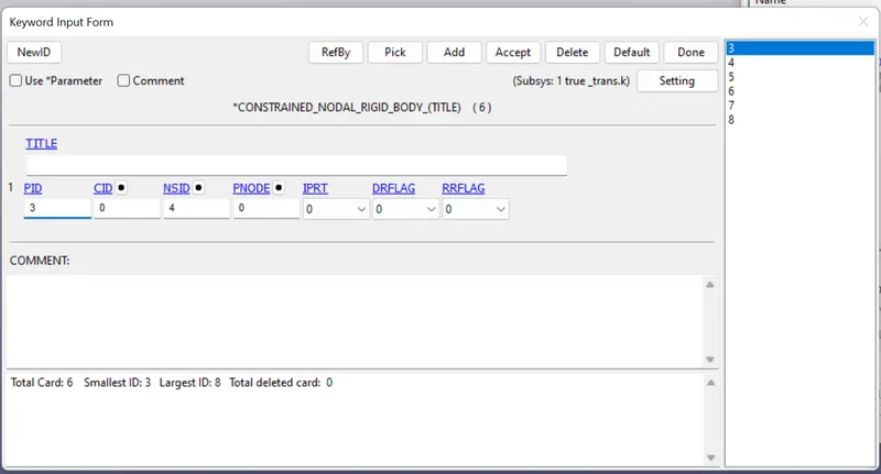
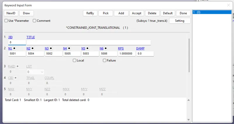
Now create constrained_join_translational card using model&keywords>all>Constrained. Here we need to assign nodes for the respective parts. N1&N3&N5 for part 1and N2&N4&N6 for part 2. assign the values as per the parameters.
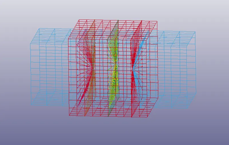
Now define initial_velocity card using model&keywords>all>initial. Define part id and X axis translational as 10mm/ms. the translational only at x-axis.
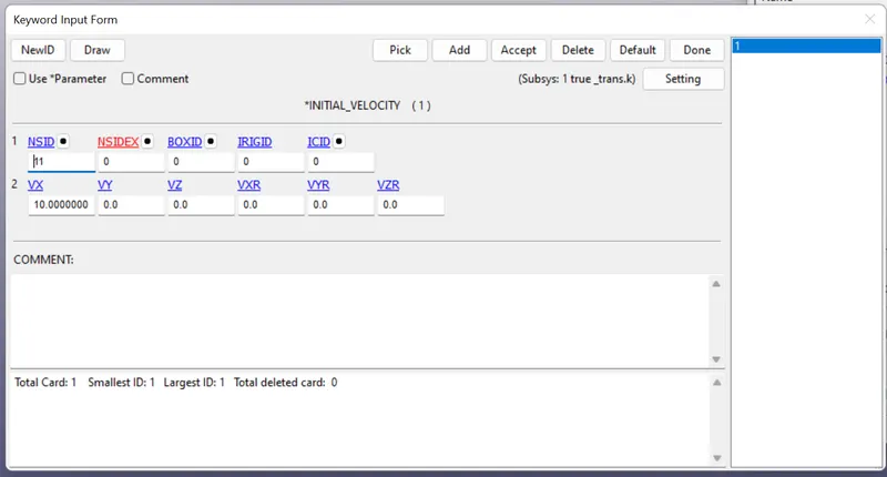
Now define the control card for the simulation. define control termination card in model&keywords>all>control. Now put end time as 10ms.
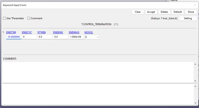
Define binary d3plot for output animation file. go to model&keywords>all>database>binary d3plot. Here assign DT value as 0.1.
Animation files:
Joints between rigid bodies:
Revolute joint:
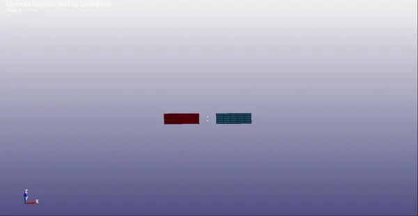
Spherical joints:
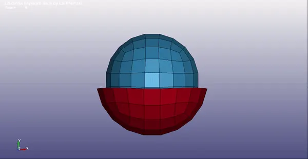
Cylindrical joints:
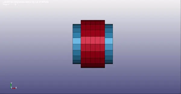
Translational joints:
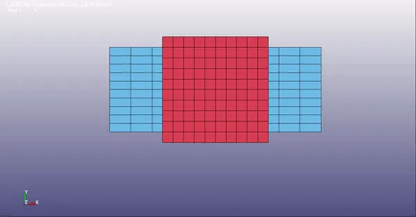
Joints between deformable bodies:
Revolute joint:
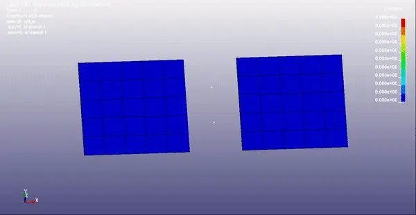
Spherical joints:
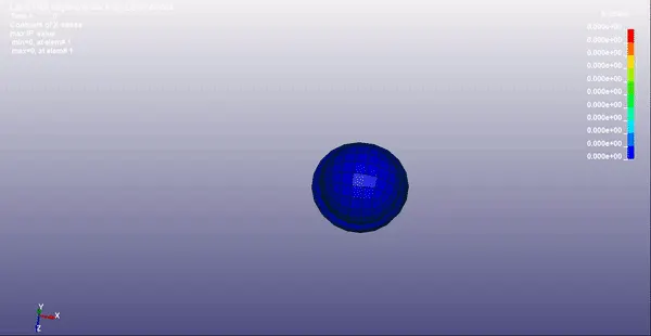
Cylindrical joints:
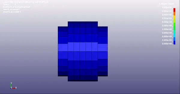
Translational joints:
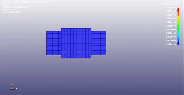
RESULT:
- The necessary keyword files are created for joints between rigid bodies such as spherical, revolute, translational, cylindrical joints using constrained_extra_nodes and constrained_joint tools.
- The necessary keyword files are created for joints between deformable bodies such as spherical, revolute, translational, cylindrical joints using constrained_nodal_rigid_body(CNRB) and constrained_joint tools.
- Finally ran the simulation and animation files were above