Week 11: FSAE Car Project
Question:
You will be provided the model file of the car. This project is divided into two phases.
Phase 1: Geometry cleanup
NOTE:
Dimensions of the geometry are in INCHES.
Make sure you are scaling it properly in CONVERGE STUDIO so that dimensions are in meters as converge accepts the dimensions in meters.
- Cleanup the 48 errors
- Flag the front wings, rear wings, tyres, suspension links as separate boundaries
- Create a virtual wind tunnel
- Ground plane reference is provided in the lower end of the tyres. There will be a "flat section" in all the 4 tyres. This refers to the location of the ground plane. You will have to create the ground plane and perfectly merge it with the tyres.
- Run a virtual wind tunnel no-hydro test and a coarse simulation test to prove that you have finished face 1 correctly.
- For phase-1, the virtual wind tunnel boundary conditions and physical models can be assumed. If your simulations runs, you will be given full graded for this phase.
Phase 2 - Detailed Setup
ABCD Racing company is looking to perform Aero Simulations for their FSAE vehicle and they have hired you to do the job. The suspension team wants a detailed report on the total downforce on individual components. They have two races in this upcoming season.
Race details are as follows
Race-1
- Racing track conditions - Lot of turns
- Average lap speeds - 45kmph
- 70% turns at 45 degrees
- 20% turns at 80 degrees
- 10% turns at 20 degrees
Race-2
- Racing track conditions - Straights
- Average lap speed - 75kmph
For both theses races, summarize the CFD operating conditions. Create two separate case setup.
Create refined case setups and send it to us and we will review your refined case setups and if setup looks good then we will share the results for the refined case which we have already ran in our cluster.
NOTE:
We will not be running the refined case which we are asking you to share with us. We are asking to share with us the refined case setups to check if you have refined the mesh correctly or not.
NOTE:
In regions and initilization, value of velocity should be same as that of Inlet velocity.
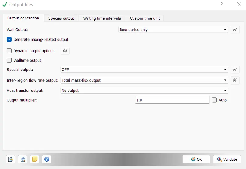
Also, while setting up the case, make sure, wall output (BOUNDARIES ONLY) is enabled as this will dump wall averaged output data which is very much important for any external aerodynamic simulations.
This can be done by going into OUTPUT FILES under OUTPUT/POST PROCESSING in the case setup tree.
Answer:
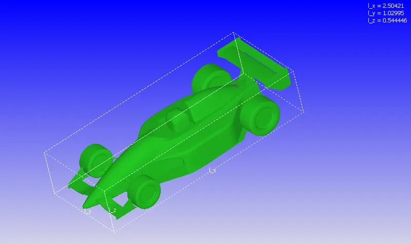
Importing the geometry & also converting from inch to meter using scale option given in the dialogue box.

The dimension of bounding box shown in below image is meter unit.
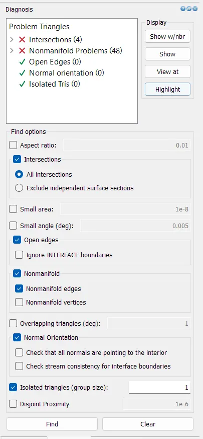
Initial diagnostic report
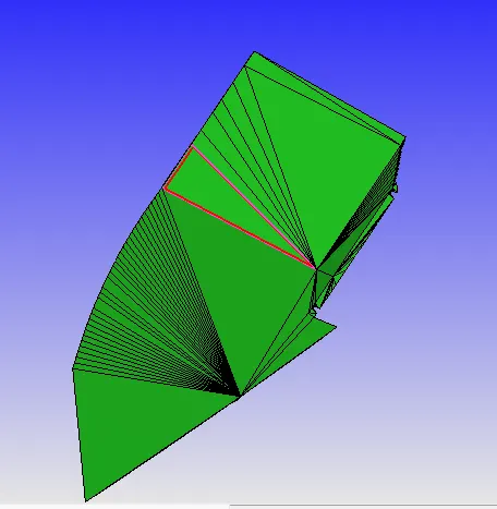
Following errors are displayed in images to visualize the problem area into the geometry which were resolved using the Converge tools.
Intersection error
To solve this, the elements with neighbouring elements were deleted & recreated using the patch command.
Nonmanifold Problems
The nonmanifold error means the edge is shared with more than two triangles.
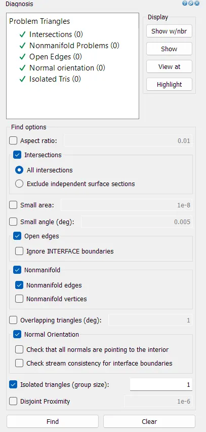
Final diagnosis report after solving all errors in the geometry.
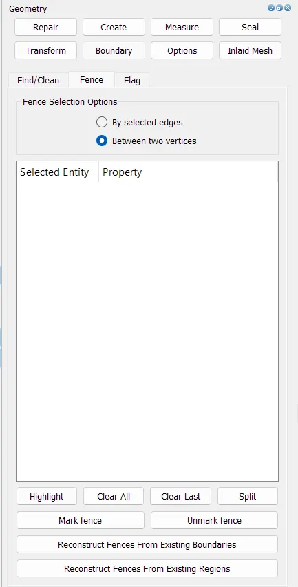
The geoemtry has been divided into multiple components like wheels, wings, body, underbody, humans & suspension using fence command. Initially fence was developed by selecting edges or vertexes.
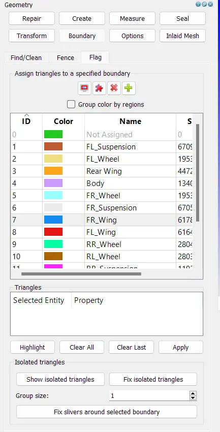
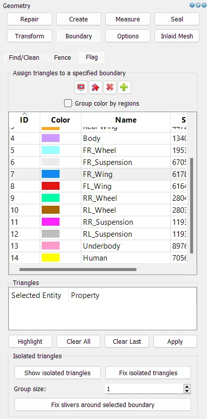
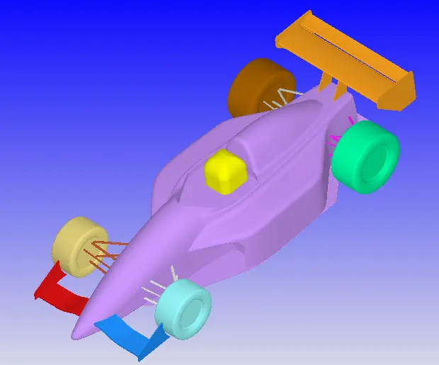
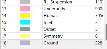
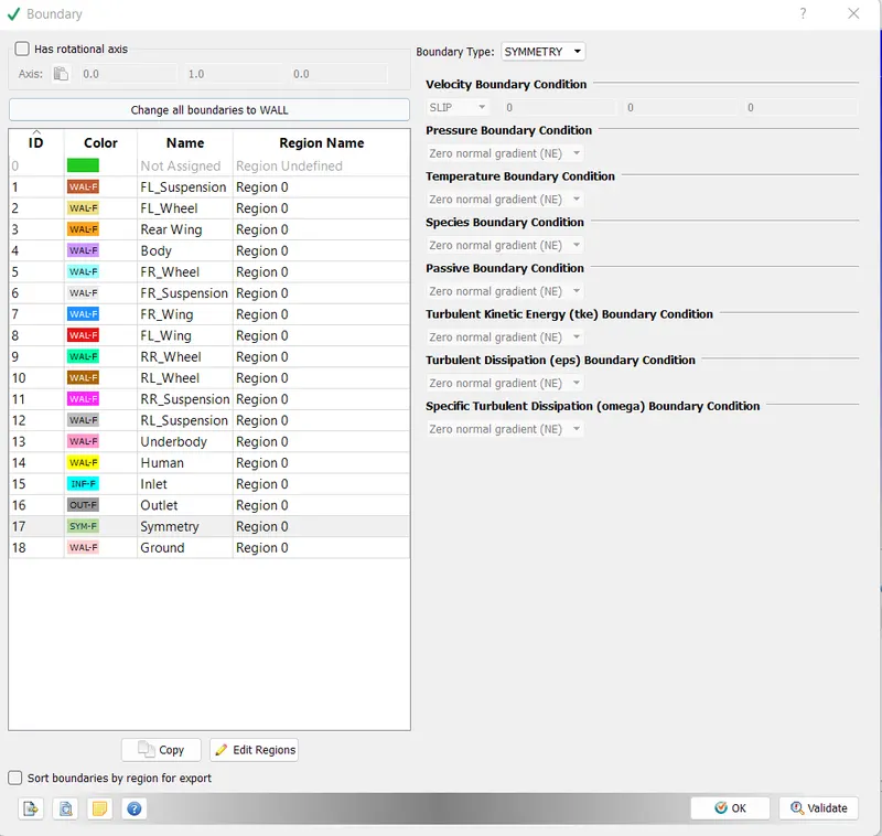
After seperating different parts of the vehicles, the boundary has been assigned to each individual component. The purpose of doing this to calculate the drag coefficient at individual component level.
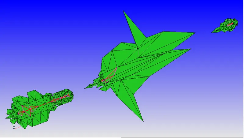
Following image shows the components with different boundaries.
The resting portion of the ture at the ground has been removed to make the surface at that location parallel to the ground.
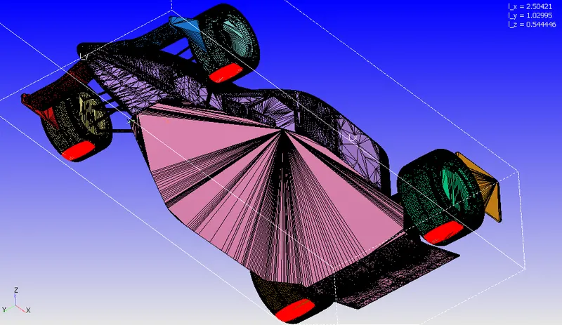
Above selected faces were deleted & the location of the vertexes were crosschecked after selecting randomly to make sure all vertexes are lying on the same plane or not.
Wind Tunnel
Following image shows the dimensions of the virtual wind tunnel created in Converge CFD software.
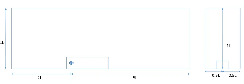
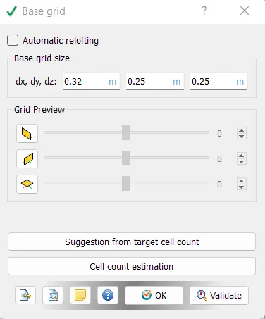
Due to size of the wind tunnel size, limited computational resources & limitation of software's education version, mesh will be coarse to satisfy all limitations.
Vertexes have been created at following locations:
-5.0, -2.5, -1.1612e-02
-5.0, 2.5, -1.1612e-02
-5.0, -2.5, 2.5
-5.0, 2.5, 2.5
12.5, 2.5, 2.5
12.5,-2.5, 2.5
12.5, -2.5, 1.1612e-02
12.5, 2.5, 1.1612e-02
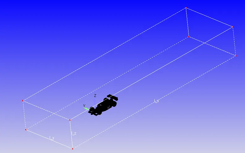
The edges were created by connecting vertexes & later on surfaces were generated using the edges with the help fo loft command. The surface could have beed created by connecting vertexes.
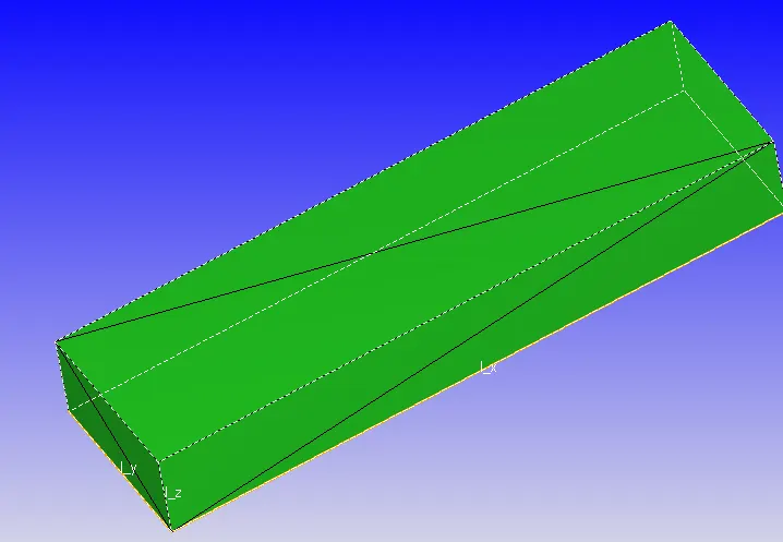
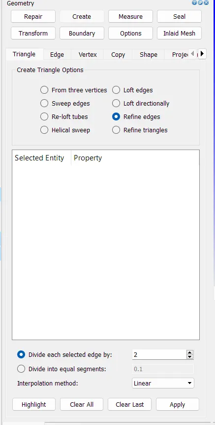
To create vertex in between two end vertexes of the edge, refine edge command is very useful. The centre vertex will help in generating surfaces with much ease.
The surfaces were created using the end vertex & centre vertex with the edges of the removed portion of the tyre surface.
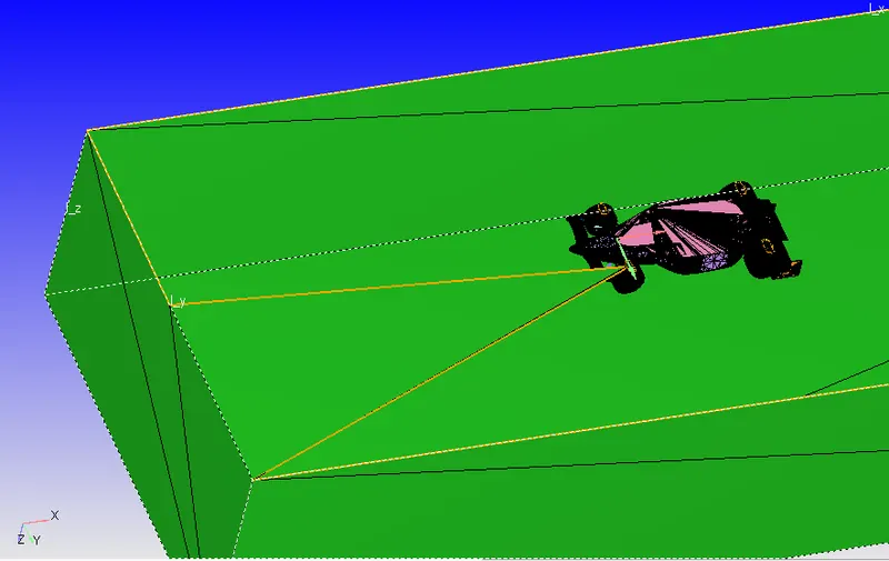
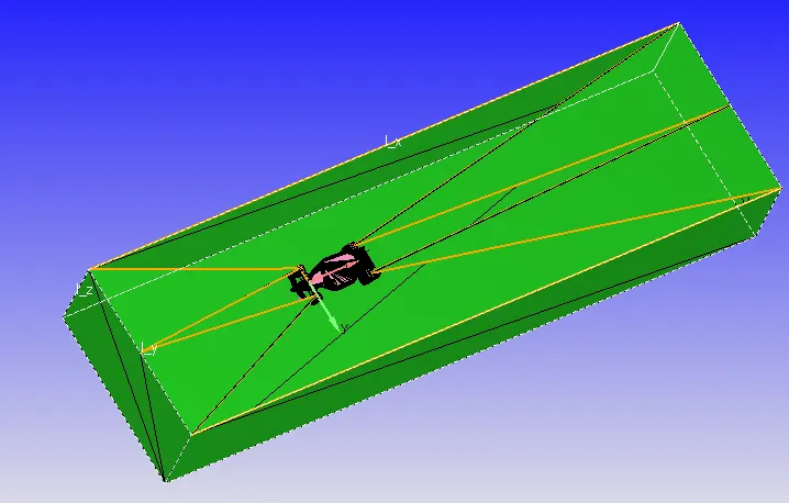
Later using the open edge option, the patch command is used to fill the gap between surfaces.
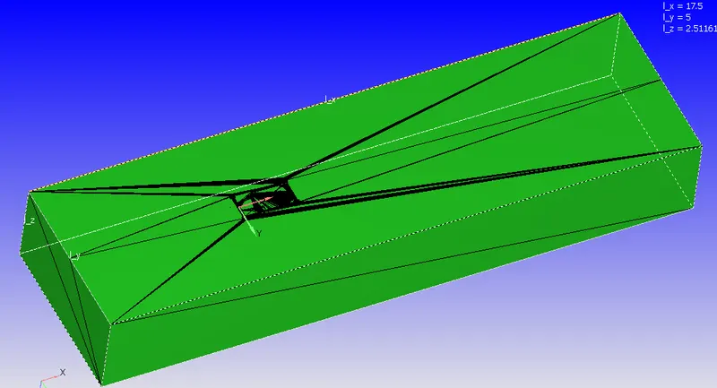
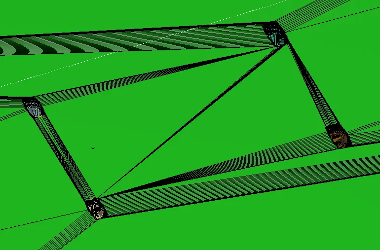
The boundaries were assigned after that to carry out simulation.
Case Setup
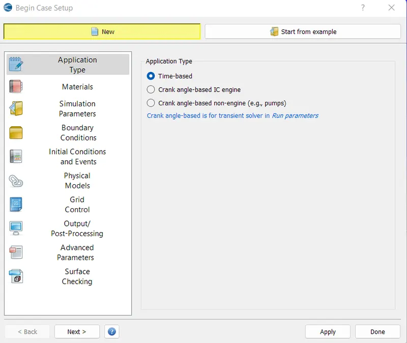
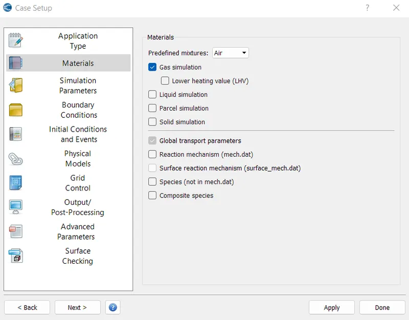
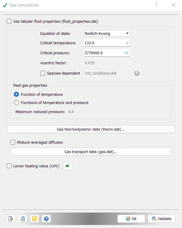
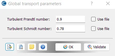
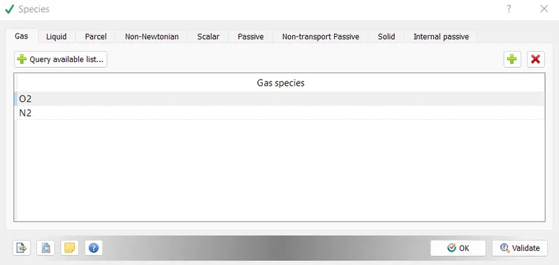
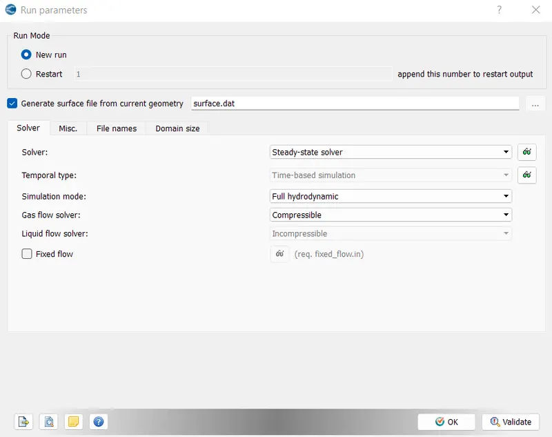
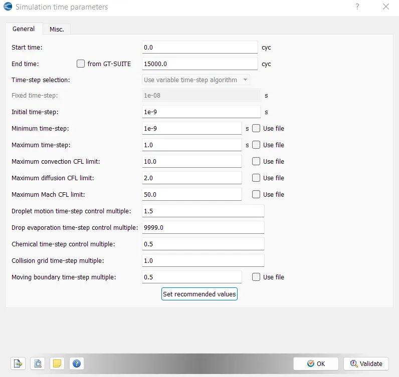
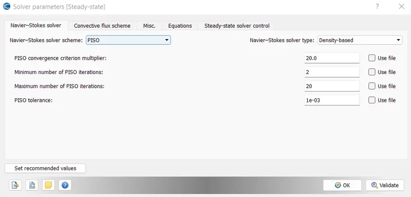
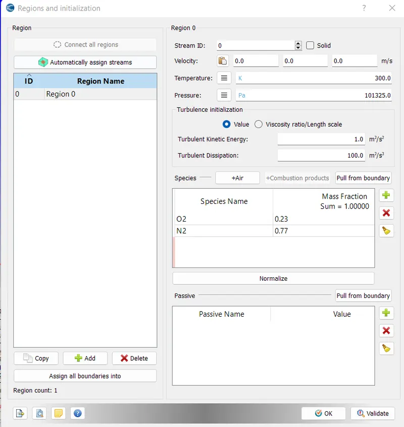
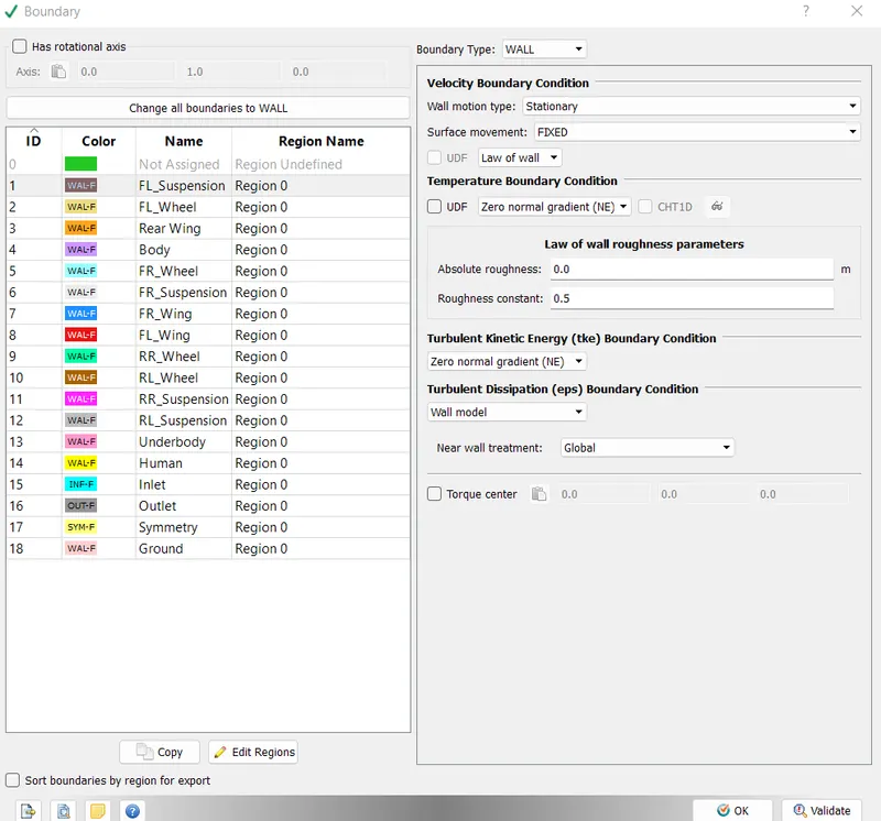
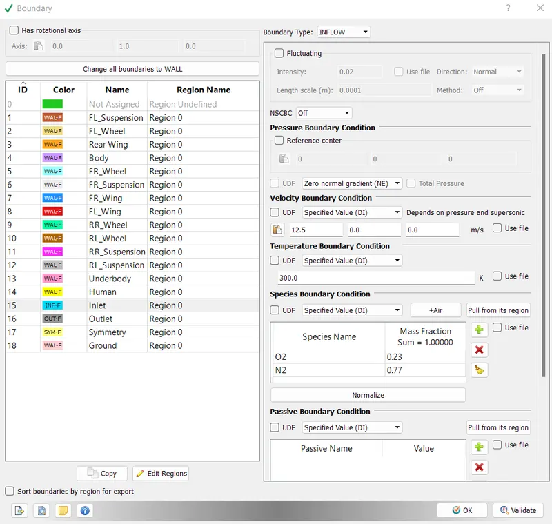
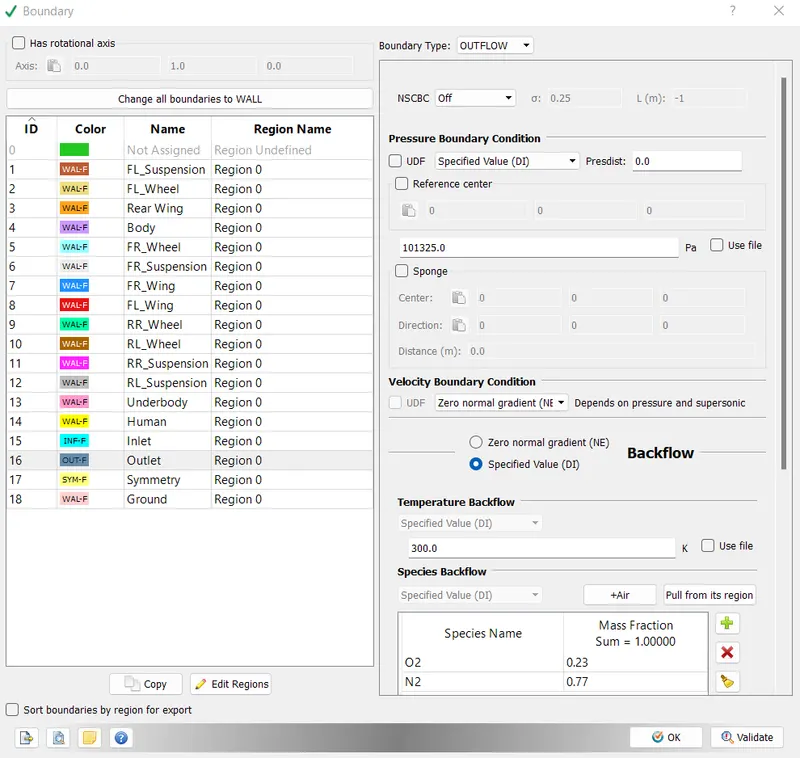
The inlet condition is set for 12.5 m/s as per video. But this simulation took almost 18 hours to complete in transient condition, I didnt run another simualtion for 75 kmph because I was running out to software time limit & limitation of computational resources.
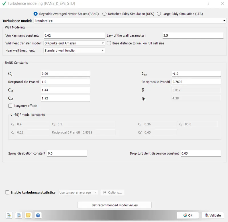
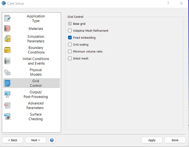
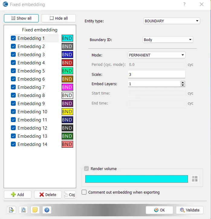
To refine the surrouding area of the vehicle, the fixed embedding option has been used. This feature helps in creating layers of elements with smaller sizes around the body to capture the boundary layer effectively.
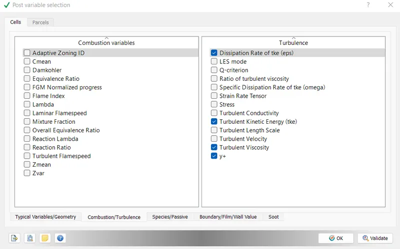
y+ option is selected from the combustion/turbulence option.
The wall output has been activated for calculating only for the generated boundaries. This option helps in calcalating pressure force in particular direction. Using this pressure force, we can calculate drag & lift coefficient.
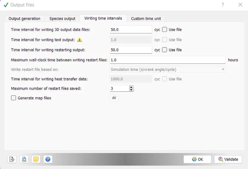
As we are simulating this problem for minimum 500 cycles & to capture minimum 10 output files, the time interval has been set as after every 50 cycles.
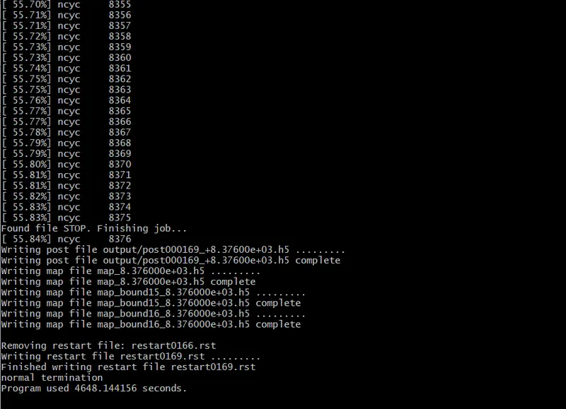
Simulation took almost 4648 seconds.
Plots
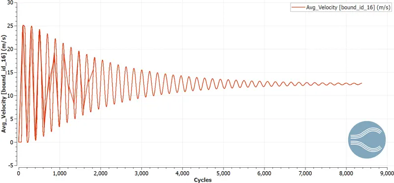
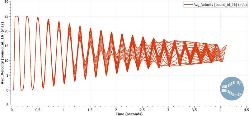
Avg Velocity at the outlet
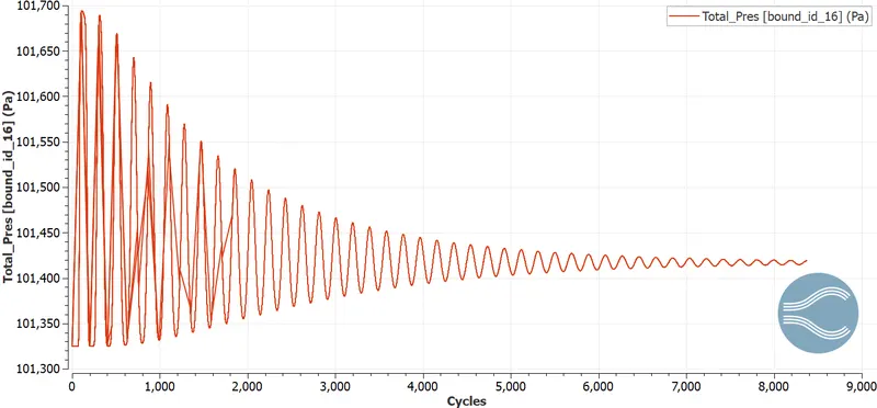
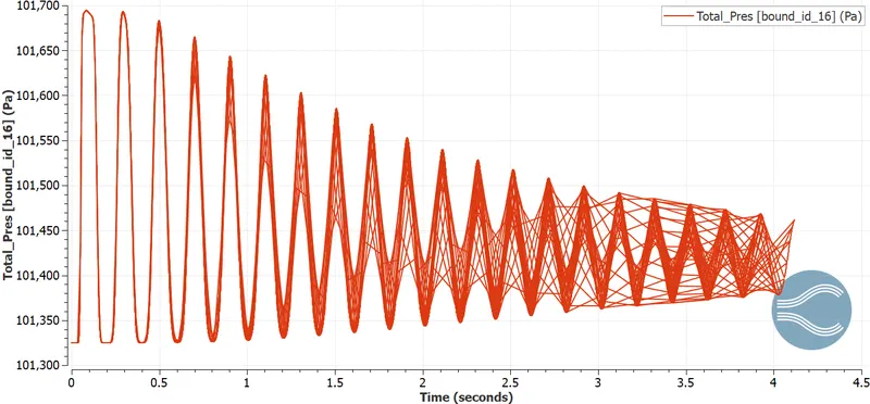
Pressure at the outlet
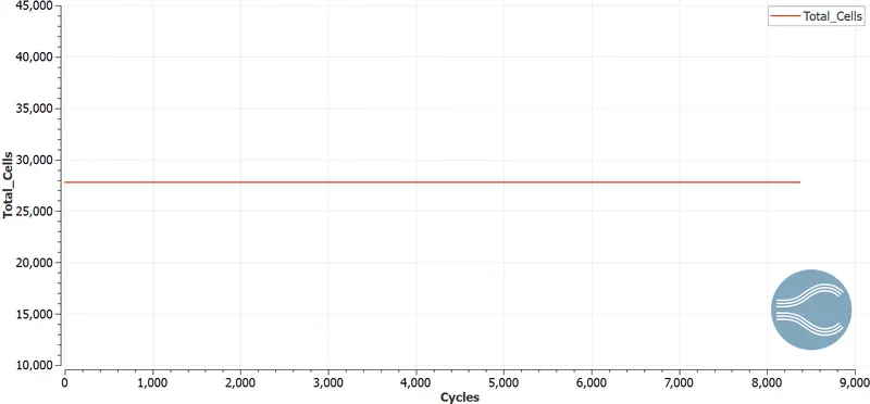
Total Cells
As my licesnes is expired & I have not performed the post conversion on steady state results, I am unable to present the post processing results of this simulation.
Transient Simulation
For transient condition, the steps which are not similar to the steady state has been displayed.
Transient simulation has been carried out for 5.2 seconds.
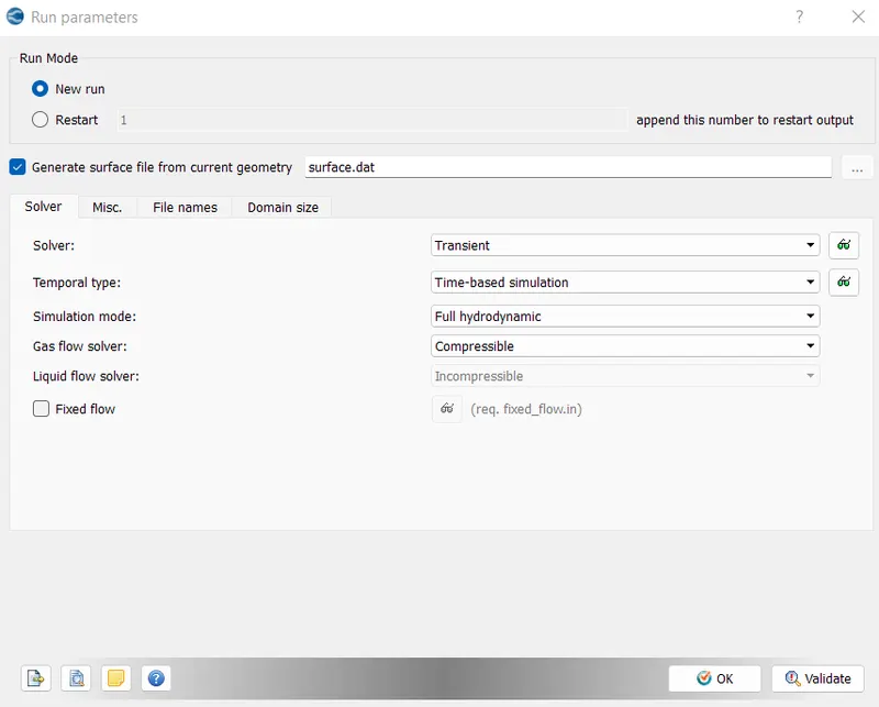
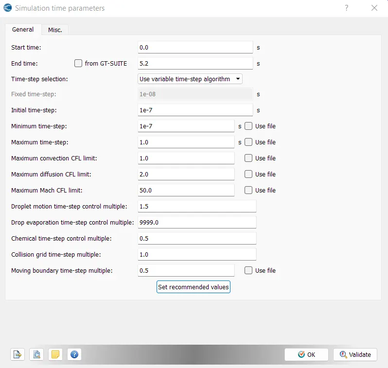
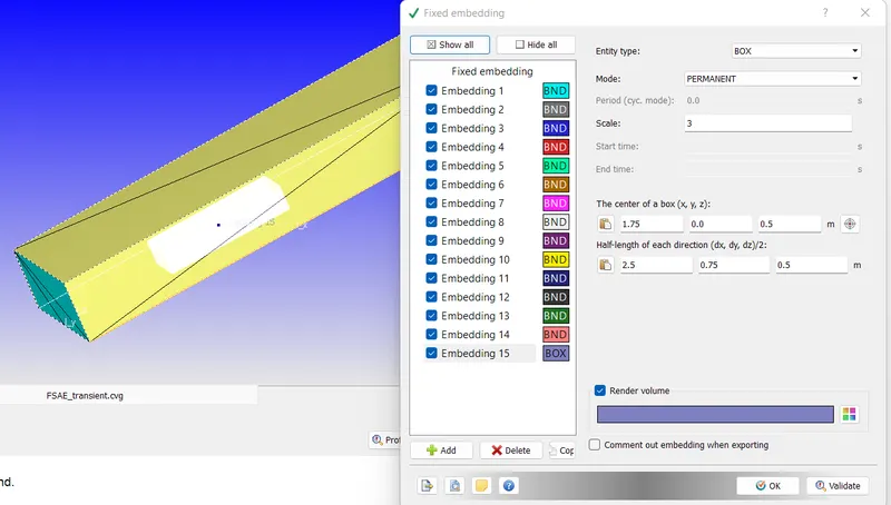
In this simulation, the surrounding area of the vehicle was optimized using the smaller element sizes using the box option. The centre of the box has been shifted & to cover atleast the length of vehicle area at the back of the vehicle, the size of the box entered accordingly.
The box size & scale to refine the elements waere reduced becaues of limitation of total number elements which be performed under student version license.
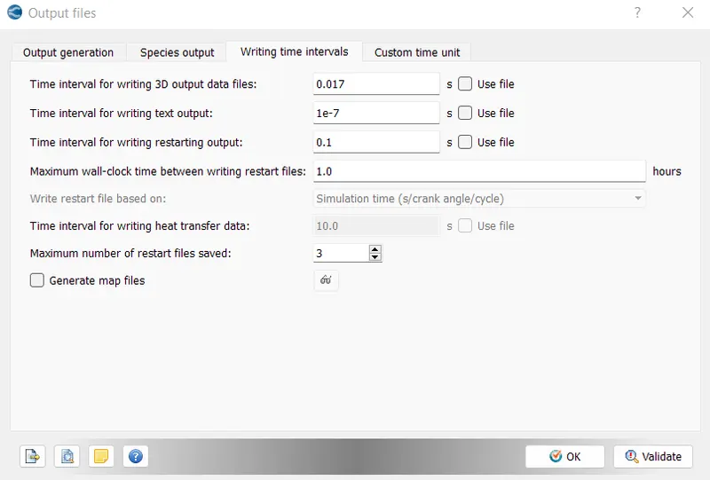
Post variable selection
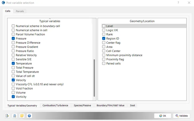
If we want to write 300 output data files than
Time interval for writing 3D output data files = 5.2/300 = 0.017 sec
The text output, we are going to write for every time step, thats why 1e-7.
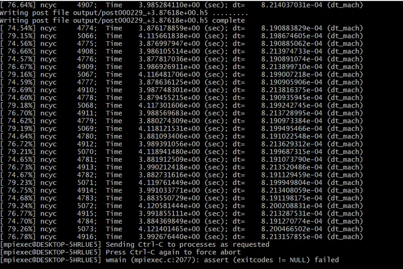
The simulalation was stopped after 4.2 seconds because it tool almost 18 hours to simulate this much time.
As it can be seen in the below image, after creating the box around the vehicle, the cell sizes has been increased 10 times.
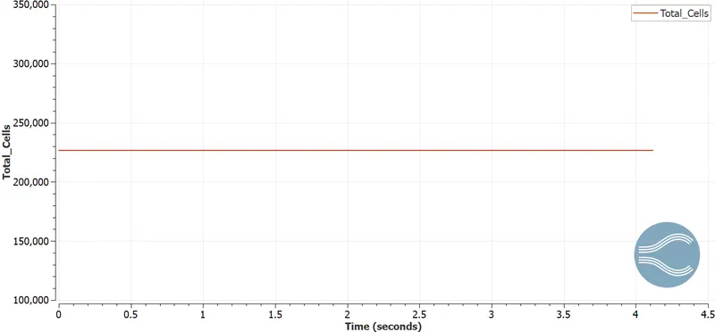
Due to expiry of my license, I am unable to provides plots of pressure force acting on each individual components.
Mesh
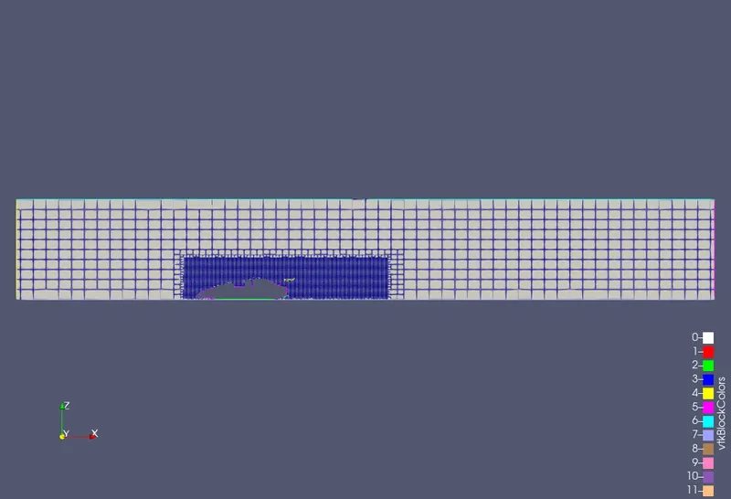
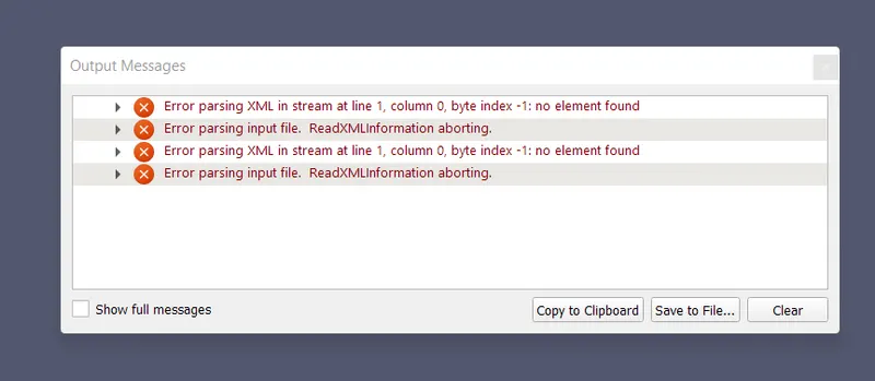
While navigating the last frame in the Paraview, I am getting following error.
As my license is expired, I am unable to run another simulation or performing post conversion process in one more time.
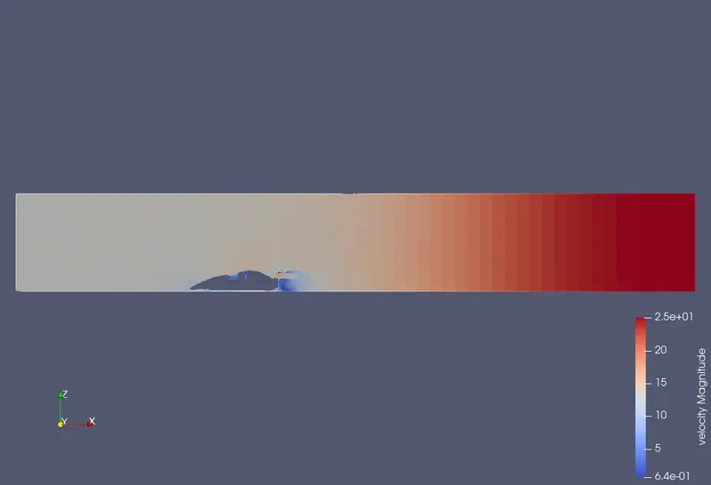
I am able to navigate upto 4th frame & because of this, i am displaying results available at 4th frame.
Velocity Contour