Week 11 - Final project
Door Trim panel
OBJECTIVE
To design the following requirement for the given class A surface and master section sketch.
- Tooling Axis creation & Draft analysis
- Class B surface & class C surface
- Close Body and thicken part
- Creation of additional engineering features.
- Assemble the push pin
Components involved in the Door panel are
- Lower Substrate
- Door Arm Rest
- Bottle holder
- Map Pocket
components of Door Panels
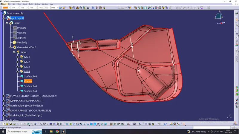
Class A surface
Class A surface for the Automotive door panel is received from the stylish team, In the automotive Industry for Class A surface Separate team is allowed to design Class-A surface this is the first input for design for plastic parts. before proceeding to further design first check the class A surface if there is any gap then modify the class A surface
Arm rest
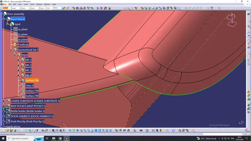
In Door arm rest, there is some clearance, we cant proceed further without rewok, so first correct the clearance in between the Arm rest Class A surface.
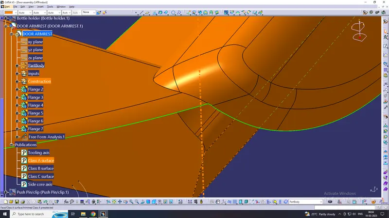
That Arm rest cclass A surface is reworked.
Tooling Axis & Drafft analysis on Class A
Creating a tooling axis
The tooling direction is used to find the direction in which the parts are removed from the core and cavity by using a tooling axis draft analysis is formed for each component.
MAP POCKET
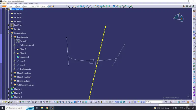
Tooling axis:
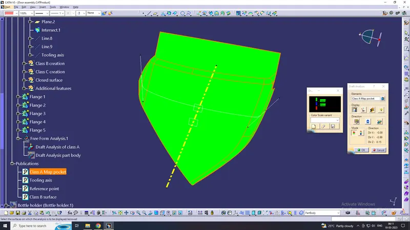
Creating a tooling direction on the map pocket, create a point on the class A surface respectively as 0 value, By using intersecting method, then create a line with respect to the Y-direction. Also, check a draft analysis for the given Class-A Surface.
Draft analysis on Class A surface:
BOTTLE HOLDER
Tooling axis:
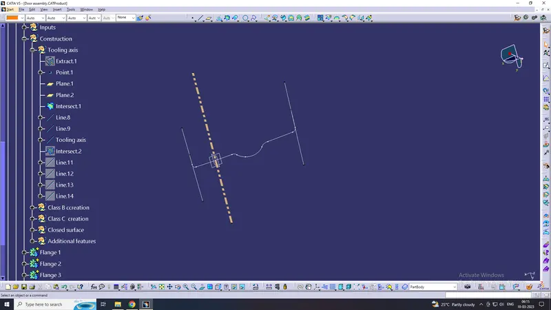
Creating a tooling direction on the Bottle holder, Create a point on the Class A surface respectively as 0 value than, By using intersecting method, create a line with respect to the y-direction Also checking a draft analysis for the given Class-A surface.
Draft analysis on Class A:
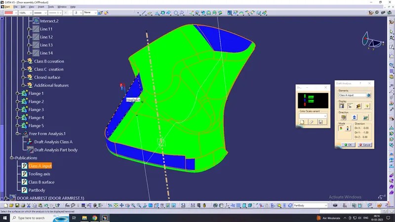
But performing a draft analysis for class A surface of bottle holder some area shows a blue surface as 0 degrees here we don't have to right to modified class A surface so we need to inform to class A team to rework the surface.
LOWER SUBSTRATE
Tooling axis:
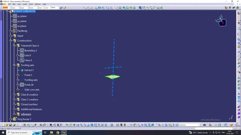
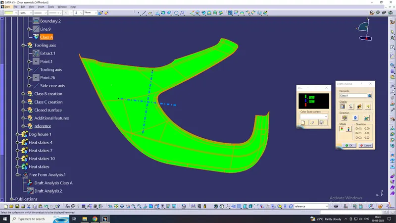
Creating a tooling direction on the Lower substrate, Create a point on the Class A surface respectively as 0 value, here we dont use inersecting method because in Y direction all faces are visible so, we create a line with respect to the y-direction also checking a Draft analysis for the given Class A.
and we create side core axis for hog house too
Draft analysis on Class A:
DOOR ARMREST
Tooling axis:
Creating a tooling direction on the Door Armrest, Create a point on the Class A surface respectively as 0 value, here we dont use inersecting method because in Y direction all faces are visible so create a line with respect to the Z-direction also checking a Draft analysis for the given Class A.
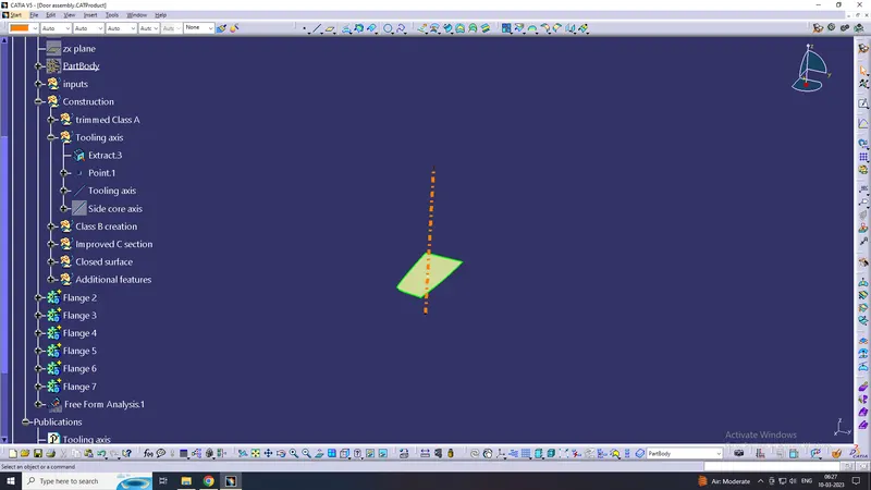
Draft analysis for Class A surface:
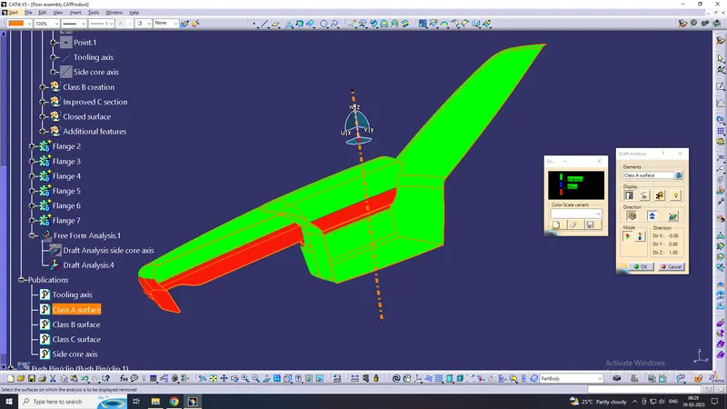
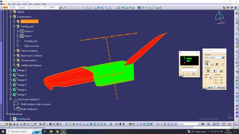
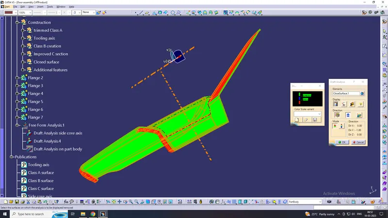
here, on Class A surface has undercut, so we create side core axis to solve undercut issue, Side core axis was created perpendicular to tooling axis on Y direction
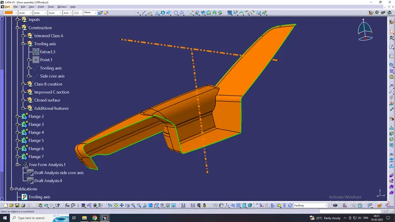
Draft analysis on Class A at side core axis:
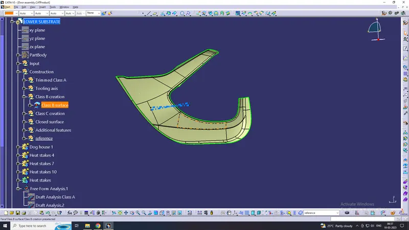
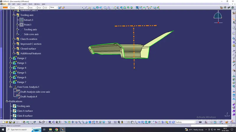
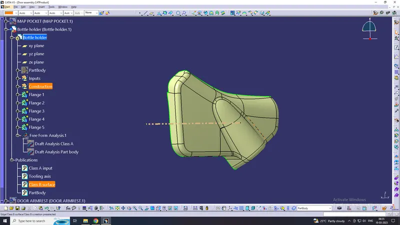
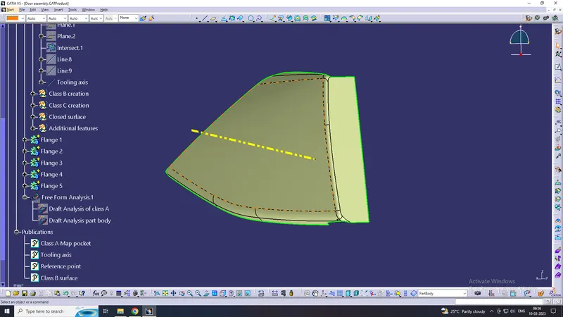
CLASS B SURFACE
Lower Substrate
Door Arm Rest
Bottle holder
Map Pocket
CLASS C-SURFACE
By extracting the boundary of class c surface and at the edges then make into them by using a smooth curve and sweep command to make c surface.
Lower Substrate
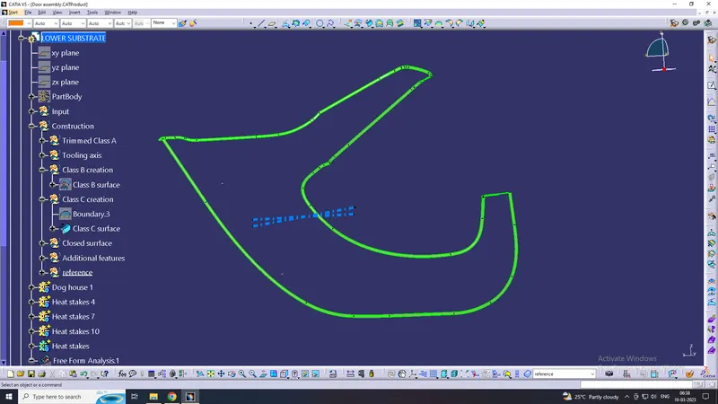
Door Arm Rest
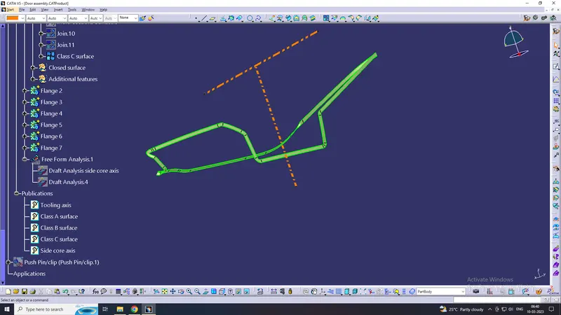
Bottle holder
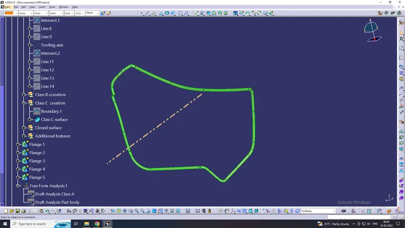
Map Pocket
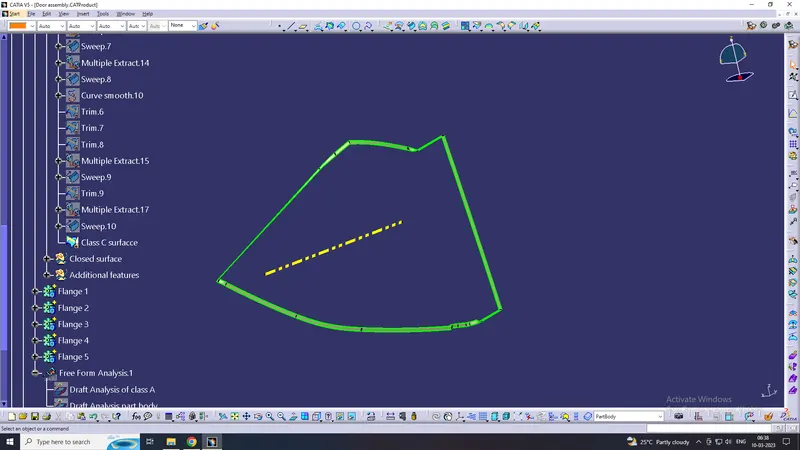
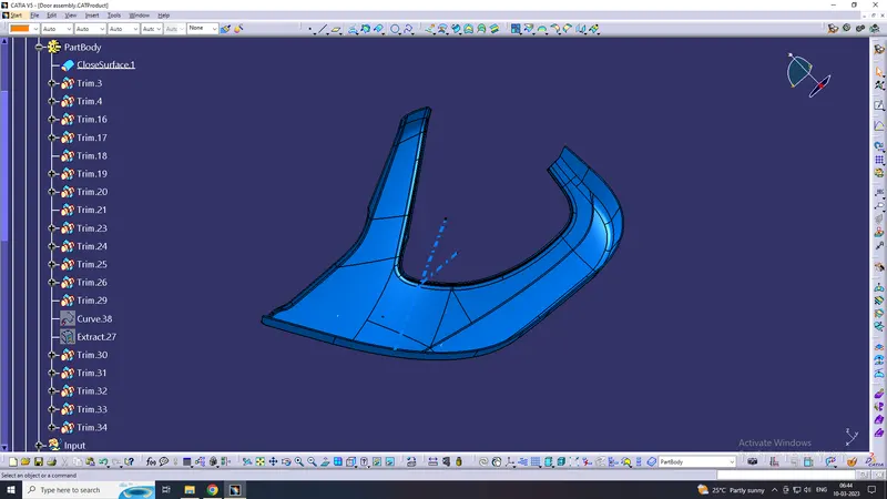
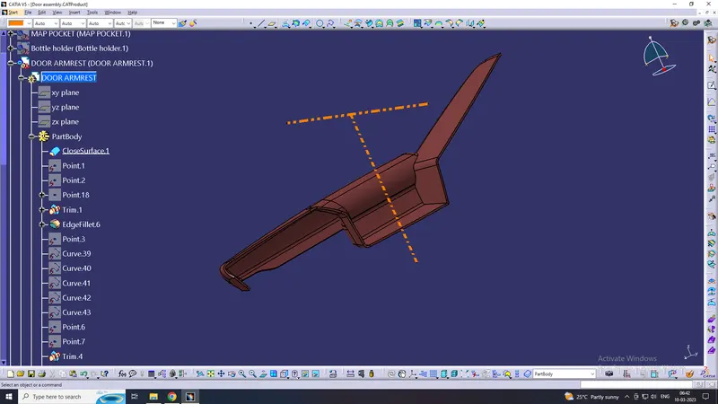
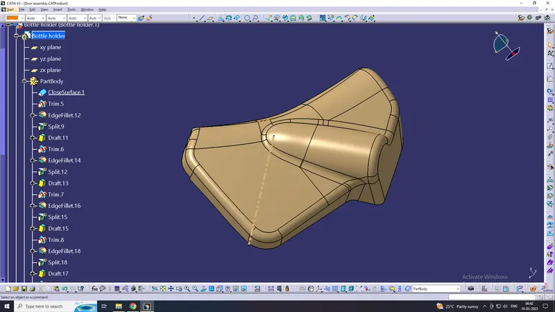
After trimming with Class C with Class B Surface and then joining with Class A surface, finally, we get the closed surface to know that use boundary option it shows as the selected body is closed.
PART BOBY
Lower Substrate
Door Arm Rest
Bottle holder
Map Pocket
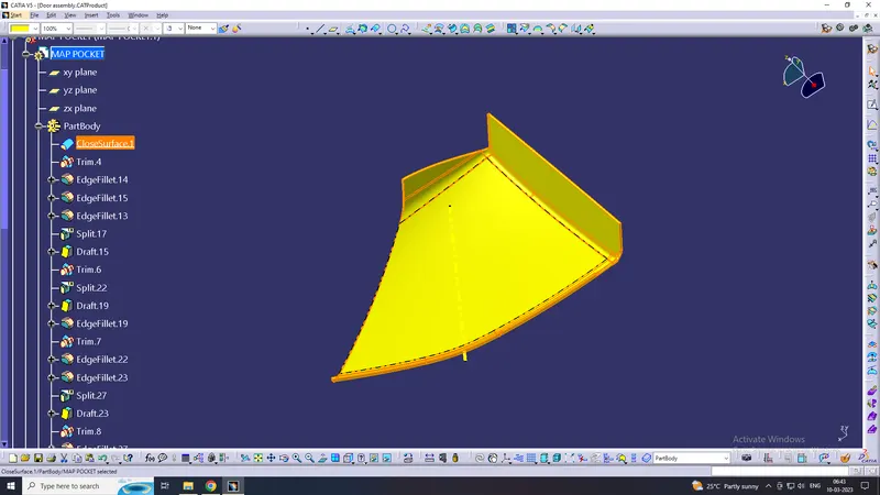
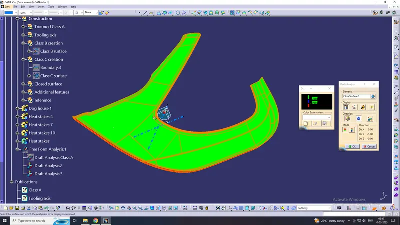
DRAFT ANALYSIS FOR CLOSED SURFACE
LOWER SUBSTRATE
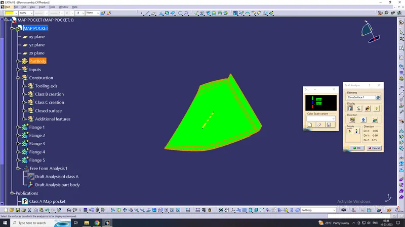
MAP POCKET
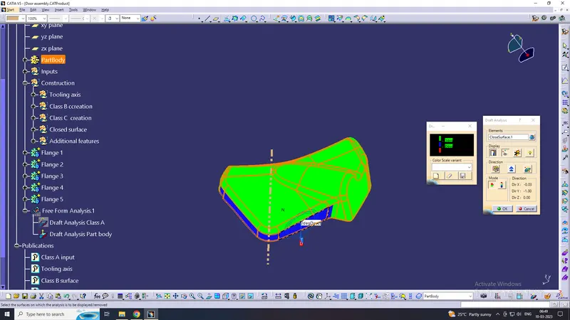
BOTTLE HOLDER
In this figure, the minimum draft angle for all faces should be 2.9 deg or above, in this color, the scale shows a draft angle of 2.9 or above. blue shows between 0 to 2.9 deg and red color show a negative draft angle, as per the above figure some faces are green, blue, and red as well hence the surface is not cleared the draft analysis at the red faces and blue faces using the main tooling axis. the minimum draft angles at the blue face are 0 deg so the class A surface needs to be given a proper draft, and required changes are forwarded to the stylish team for modification.
ARM REST
In the door, the arm rest main tooling axis clears the upper surface as shown in the figure as green color but under the cut, a tooling axis is required for the side core tooling axis is created.
Main tooling axis:
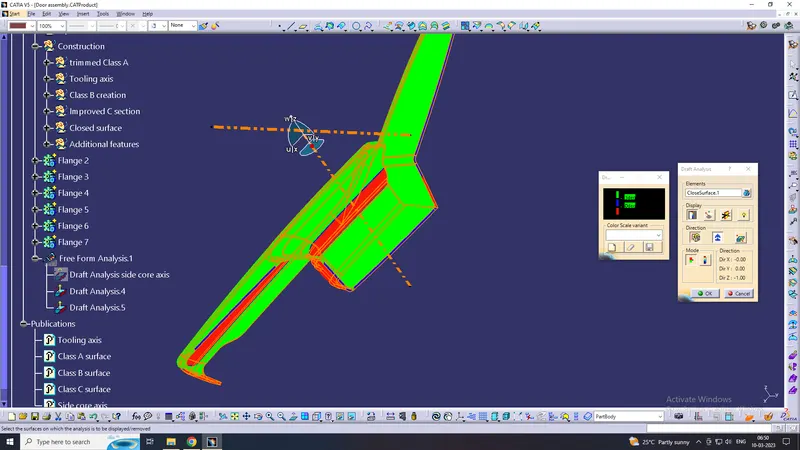
Side core axis:
ENGINEERING FEATURE / B SIDE FEATURES
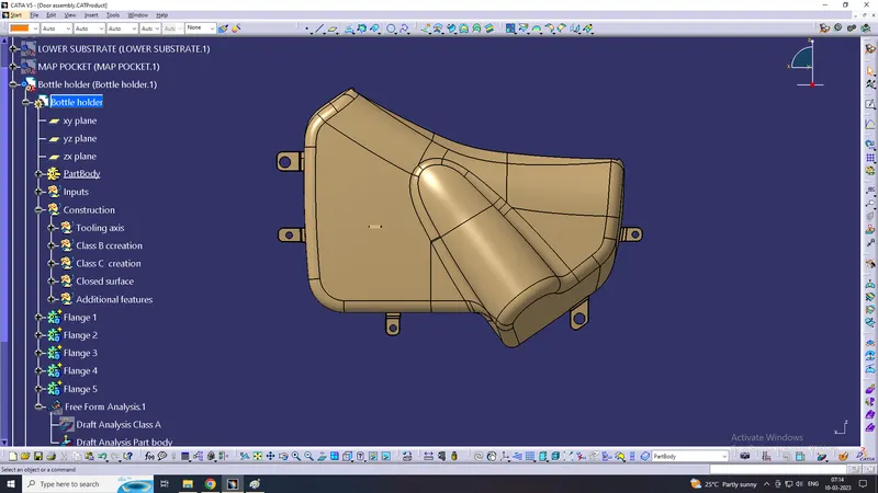
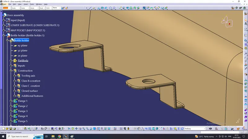
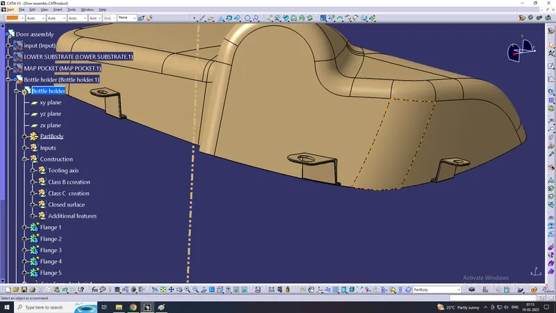
In the Door panel, all the parts are attached together by using B-side features like heat stake , Screw bosses, 4-way locators, flanges, and a Dog house.
Flanges are attached to the map pocket, Bottle holder, arm rest. The remaining features are placed on the lower substrate which will act as central parts for all the components it is mainly used to joint the remaining parts.
LOWER SUBSTRATE
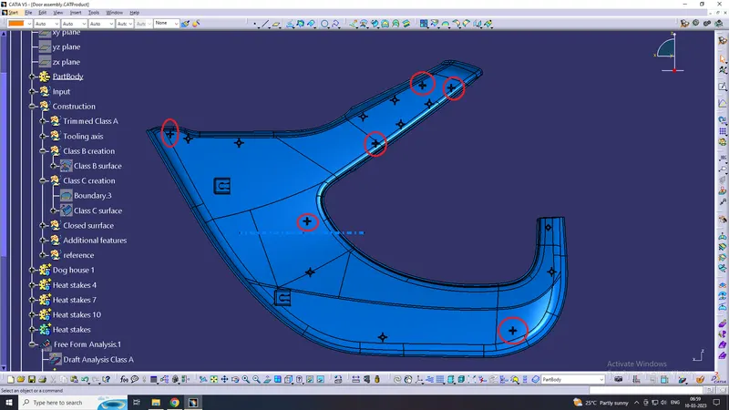
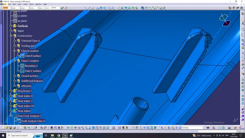
4 WAY LOCATORS:
here we produced two 4 way locators per part, so we created six 4 way locators. we created 4 way locator on both side instead of two way, because all mateing part has irregular shapes, so 4 way locator is more effective
HEAT STAKES
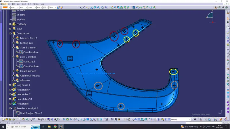
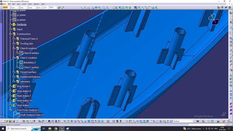
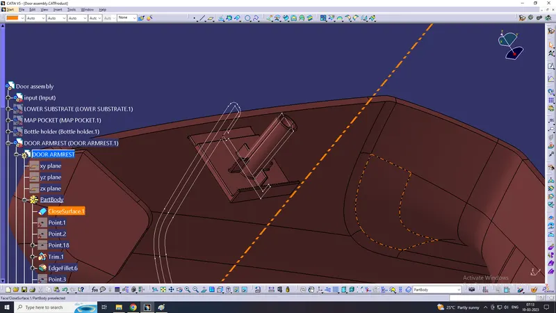
The use of heat stakes is to attach two plastic components permanently, a total of 10 heat stakes were placed at different locations on the lower substrate . Following the master section, the outer diameter of the heat stake is 7.5mm and the inner dia is 4.5mm, necessary slots are made onto other parts where the heat skate will attach together, and a draft of 0.5deg has been given to all the heat stake.
we created 4 heat stakes for arm rest, 3 heat stakes for bottle holder, 3 heat stakes for map pocket
DOG HOUSE
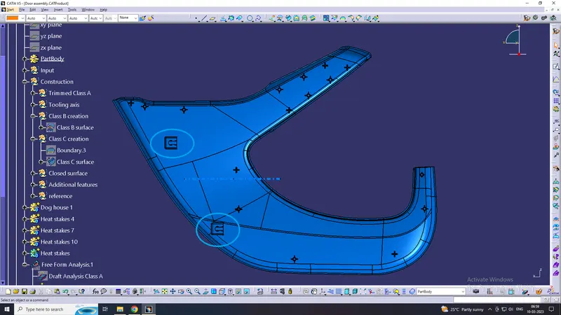
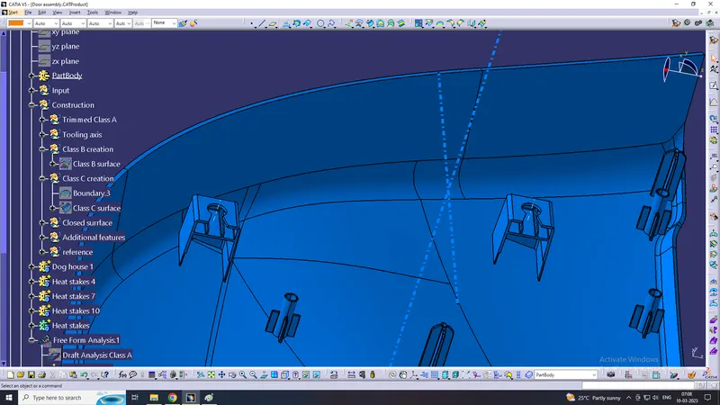
The dog house is an engineering feature used in plastic design. Dog houses are used as supporting features sometime other engineering features like snaps, locators, etc are mounted on them to increase their strength. Dog houses are subjected to draft analysis to prevent breakage of the components during ejection from the mold cavity. dog house and other engineering components are built on the B surface. here we created 2 dog house
Flanges
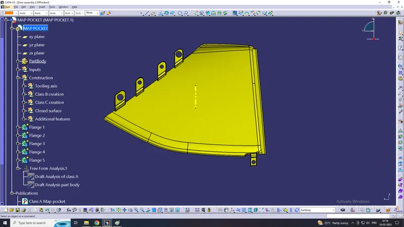
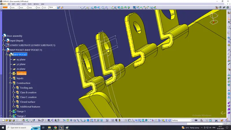
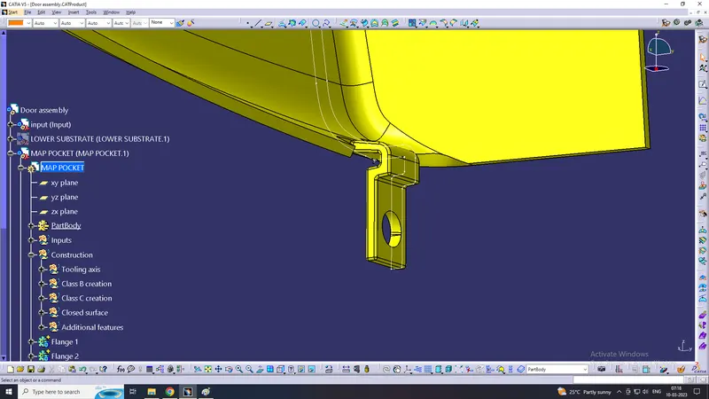
All the flanges have been created by following the given master section. the thickness of the flanges is 2.5mm, the draft angle is 0.5 deg applied to all the flanges. and also slots for locators and heat stakes have been created onto all the flanges.
Arm rest:
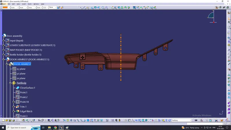
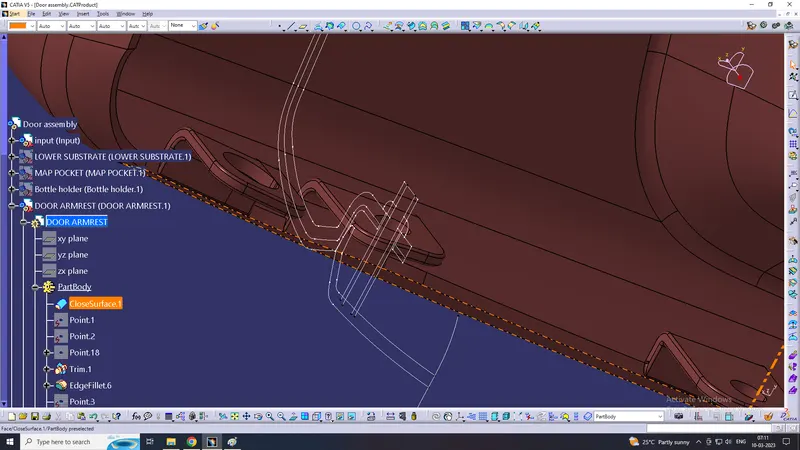
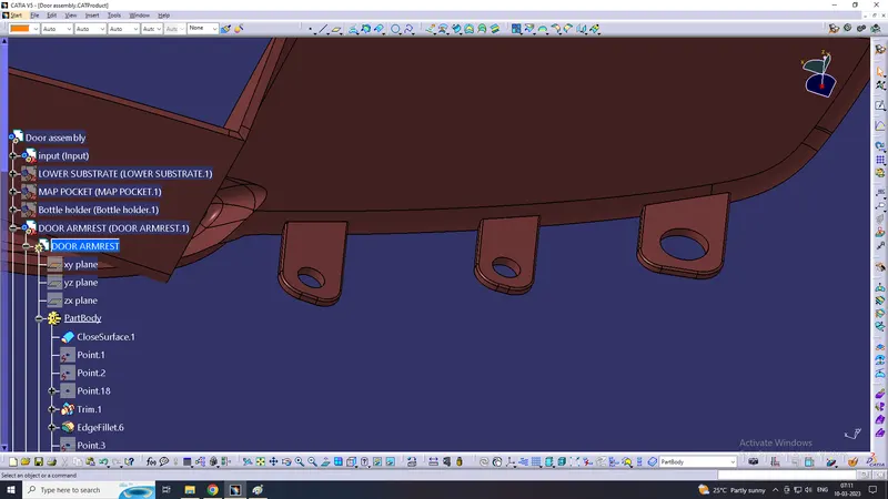
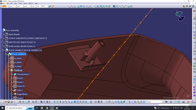
here we created dog house with heat stakes on it, because that was mandatory in master section
Bottle holder:
Map pocket:
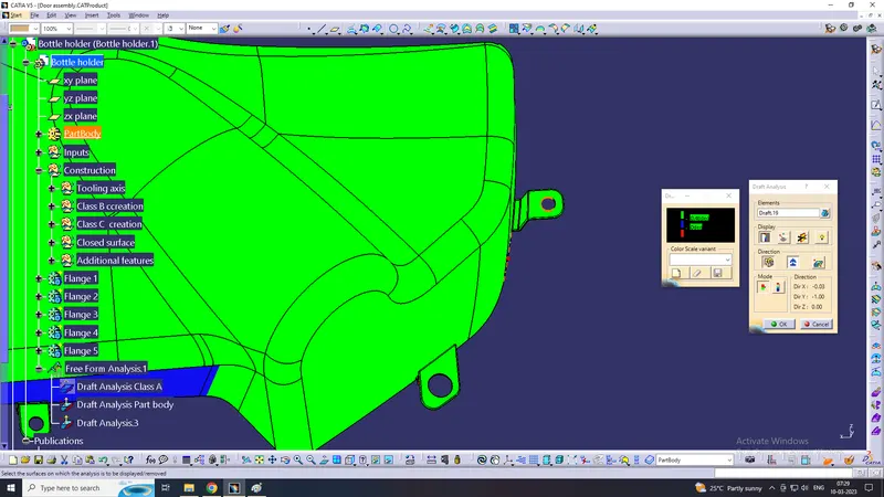
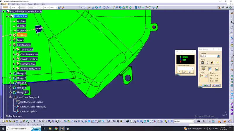
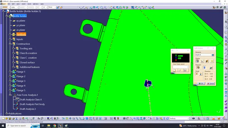
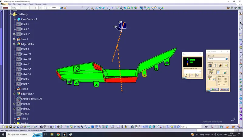
DRAFT ANALYSIS WITH ALL ADDITIONAL FEATURES
LOWER SUBSTRATE:
here we gave draft angle is 0.48 degree because some features has 0.5 degree angle
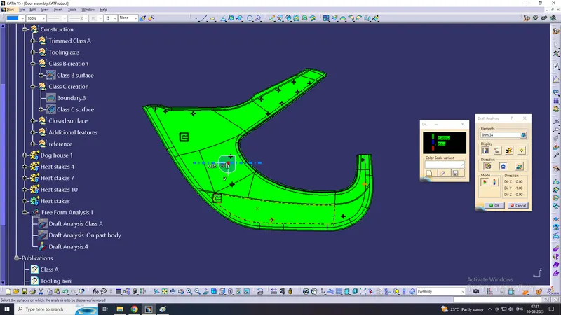
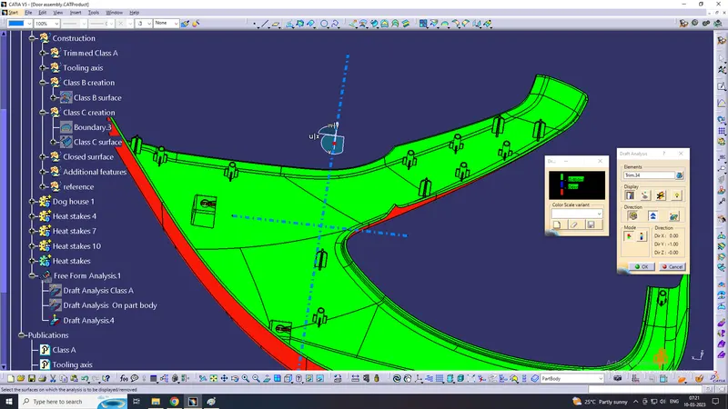
on dog house using side core axis:
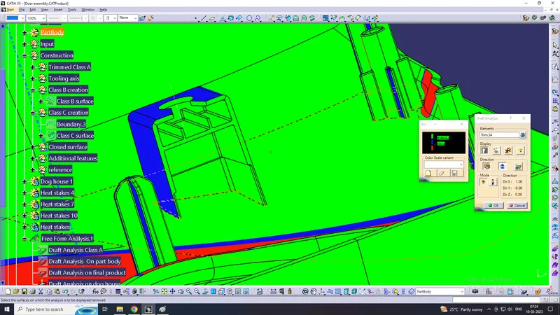
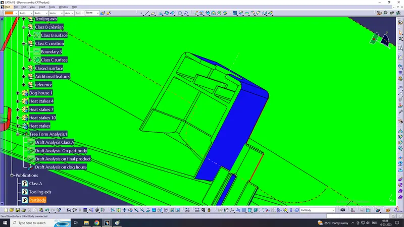
Map pocket:
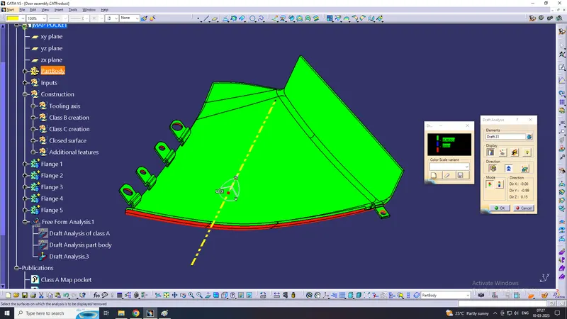
Bottle holder:

Arm rest:
ASSEMBLY PART
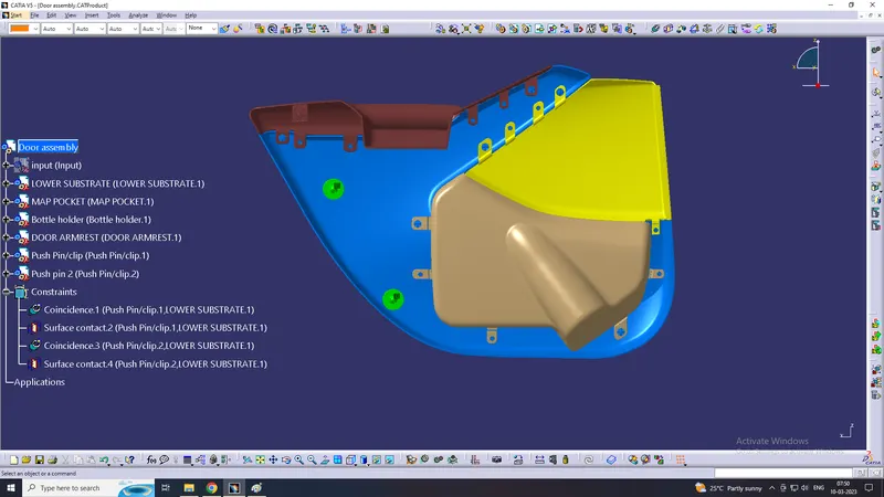
The component is created in separate part files and then inserted into assembly files they are assembled at their working position by applying constraints to them. to create an assembly using this approach, it is recommended to insert the first components and fix their position after properly orienting them in the 3D space the components can be inserted and positioned with reference to the first components.
PUSH PINS
The use of a plastic push pin is to attach the plastic part to the sheet metal part.
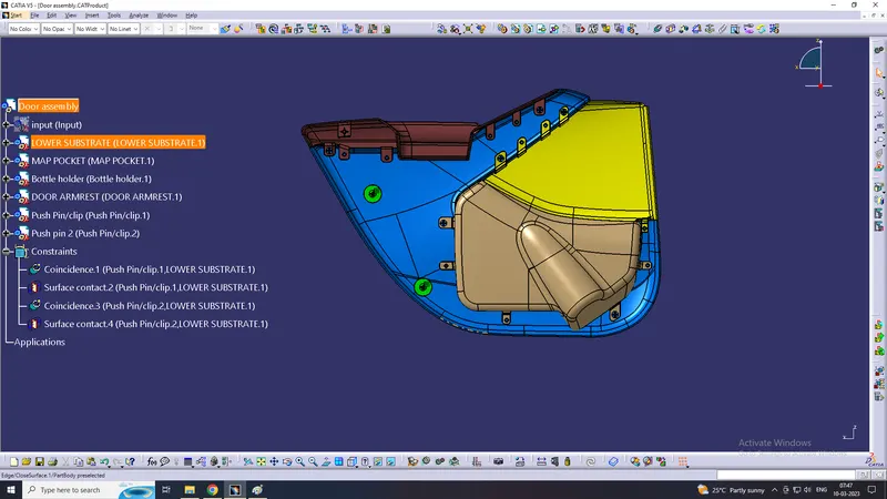
Isometric view
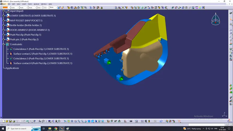
Right side view
CONCLUSION
The Door panel has been successfully designed by following standards used in the automotive industry. all the attachment features are properly placed at different locations. the designed parts meets all the designed objrctives.