Week 11 - Interior Car door Panel Final project
AIM
To create an interior door part from the inputs of class A surface along with the master section by following the design rules followed in tier 1 and OEM industries in catia v5
SOFTWARE USED
CATIA V5
OBJECTIVES
- Create a sketch by using the Positioned sketch
- All the should be sketches should be Iso-Constrained
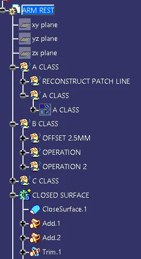
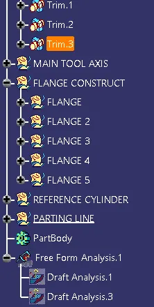
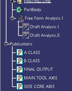
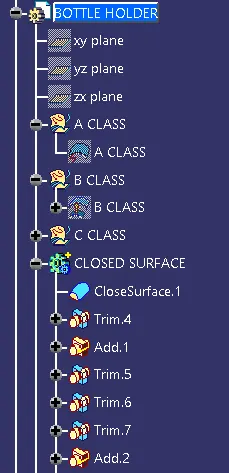
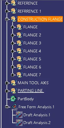
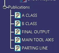
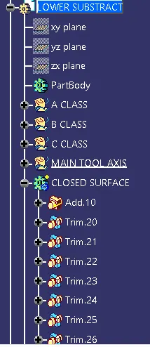
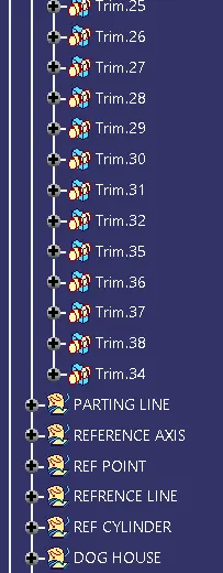
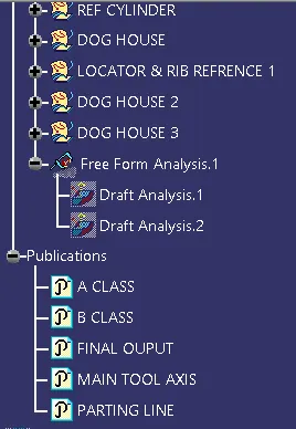
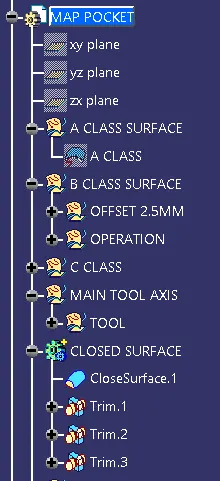
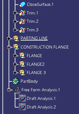
- Ensured Proper Tree Structure
- Geometrical sets should have a proper name based on the sketches present inside of it
- Create thickened part using the master section for reference
- Create the mounting features as per design guidelines in the industry and with master sections
- Creating Draft analysis & Tooling analysis
- Creation of parting lines and checking tooling feasibility
INPUT OF CLASS A SURFACE
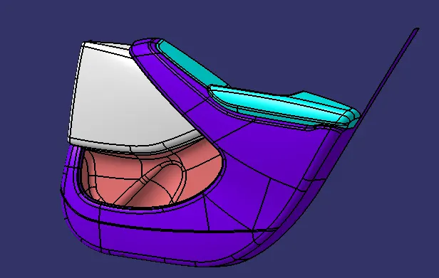
CREATION OF TOOLING AXIS - INPUT OF CLASS A SURFACE
ARMREST
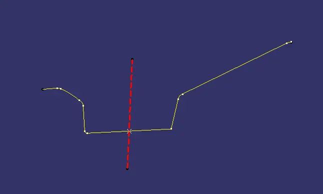
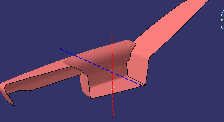
BOTTLE HOLDER
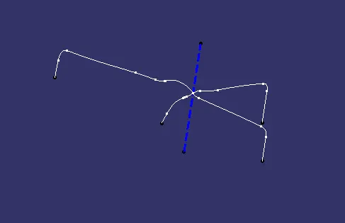
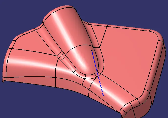
LOWER SUBSTRATE
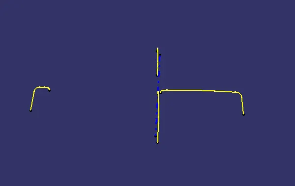
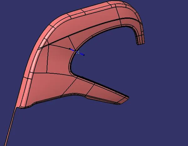
MAP POCKET
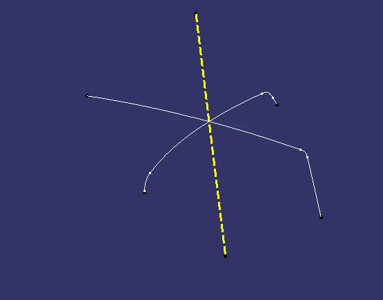
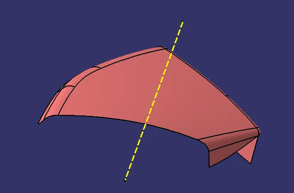
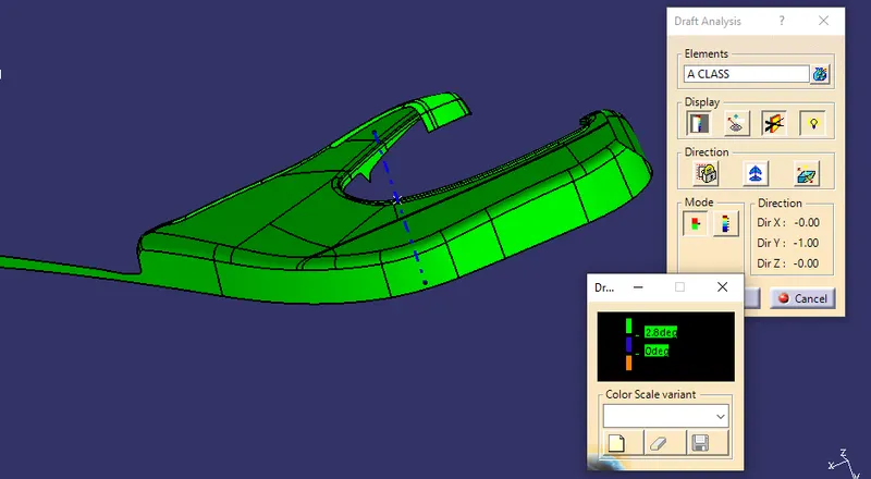
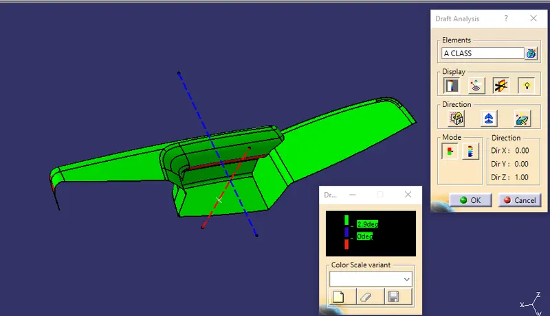
PERFORMING DRAFT ANALYSIS ON MODEL
- To perform draft analysis open customize view parameters and choose the Material
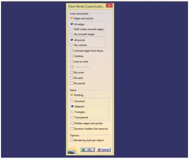
- Insert a feature draft analysis by following these commands
I insert>analysis>feature draft analysis
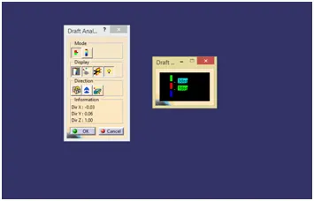
- Align the compass on the tooling axis that we created
- Open the color scale and enter the value as 3 deg.
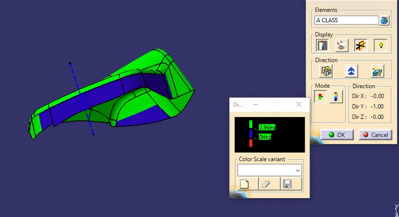
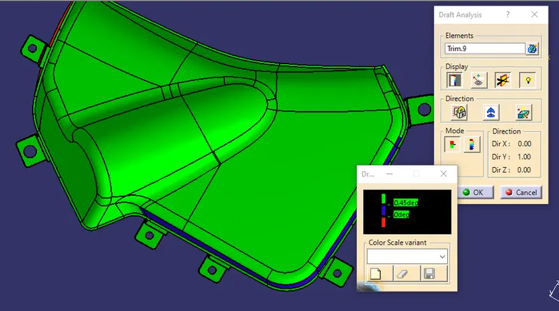
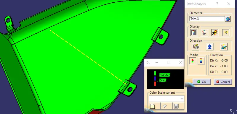
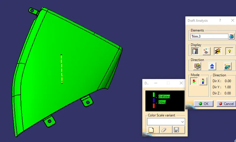
- If the whole body is green that all the faces are greater angle than the provided angle
DRAFT ANALYSIS REPORT OF CLASS A – LOWER SUBSTRATE
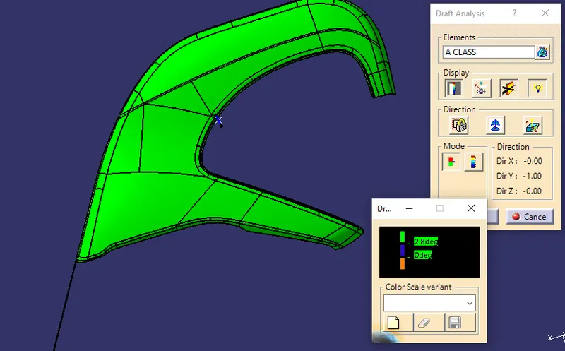
DRAFT ANALYSIS REPORT OF CLASS A – ARMREST
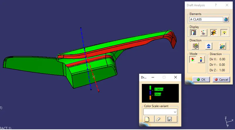
DRAFT ANALYSIS REPORT OF CLASS A – MAP POCKET
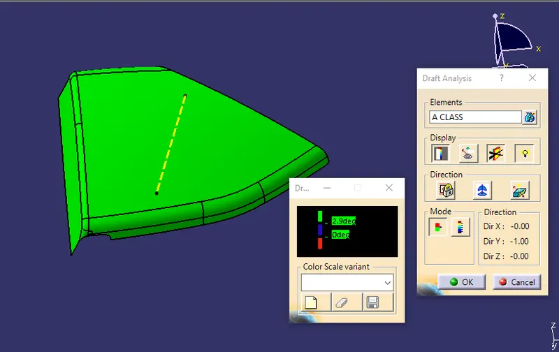
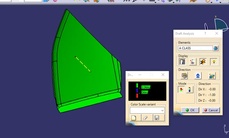
DRAFT ANALYSIS REPORT OF CLASS A – BOTTLE HOLDER
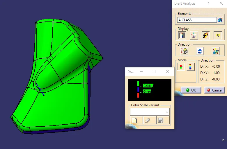
CREATION OF CLASS B SURFACE
- Insert a new geometrical set. Measure the value of thickness in the master section.The value is 2.5mm
- Offset the class A surface to 2.5mm.
- Check all the sub-elements are formed if not try to fix them locally
LOWER SUBSTRATE CLASS B
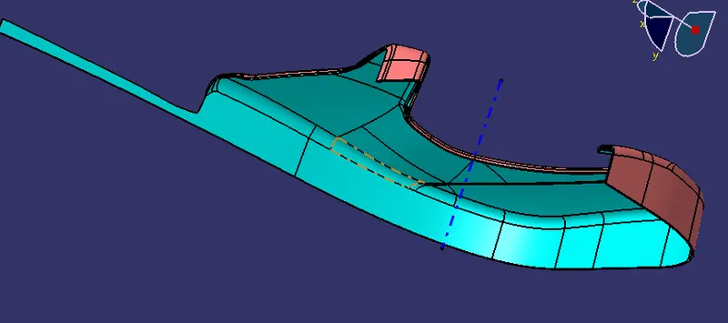
BOTTLE HOLDER CLASS B
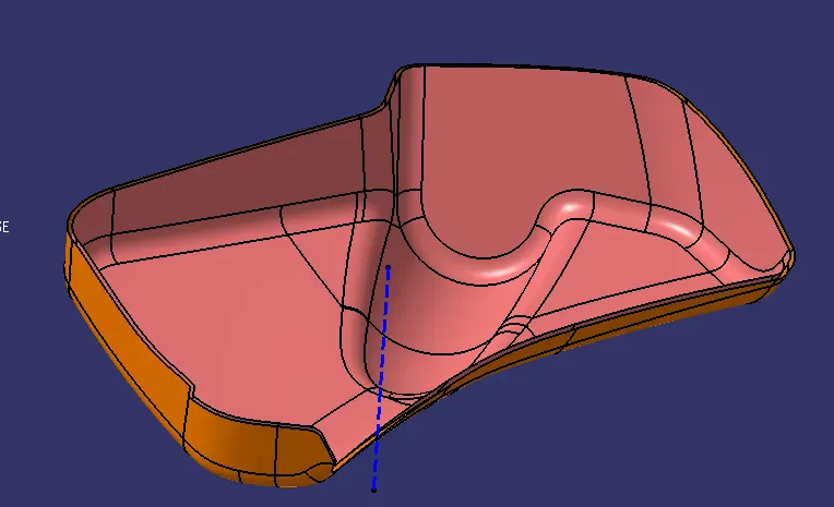
ARMREST CLASS B
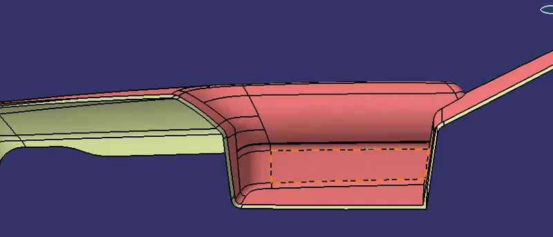
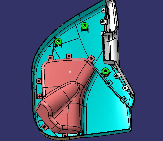
MAP POCKET CLASS B
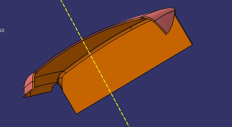
CREATION OF CLASS C SURFACE
- Analyse class A once where the sweep is easier to create toward the tooling direction
- Create a boundary using limitation points wherever possible for sweep
LOWER SUBSTRATE CLASS C SURFACE
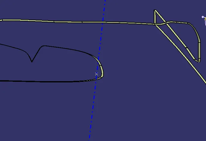
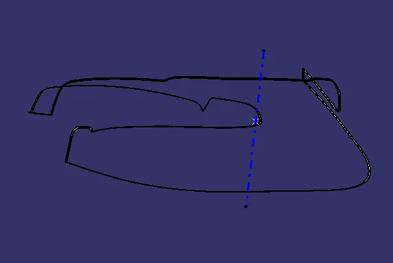
BOTTLE HOLDER CLASS C SURFACE
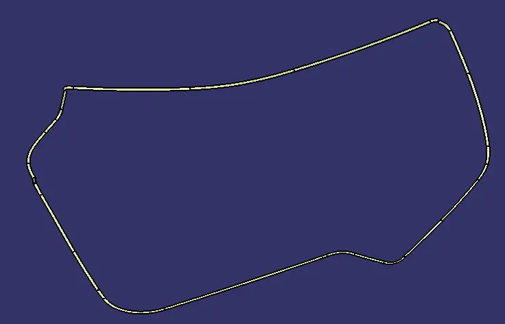
ARMREST CLASS C SURFACE
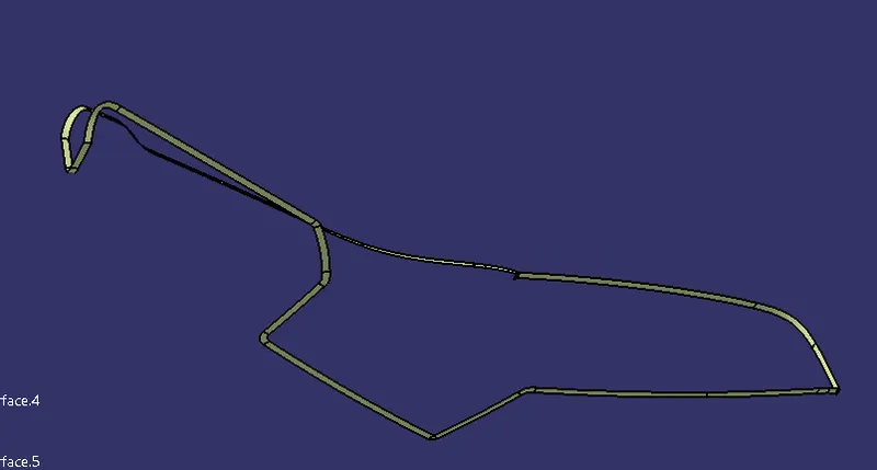
MAP POCKET CLASS C SURFACE
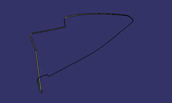
CREATION OF B-SIDE ATTACHMENT FEATURES
DOG HOUSE
- Extract the surface that we going to create a dog house
- Insert an axis system. use positioned and draw a dog house sketch
- Extrude the sketch in the direction of the main tooling axis
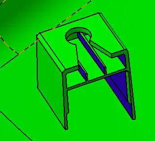
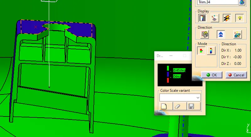
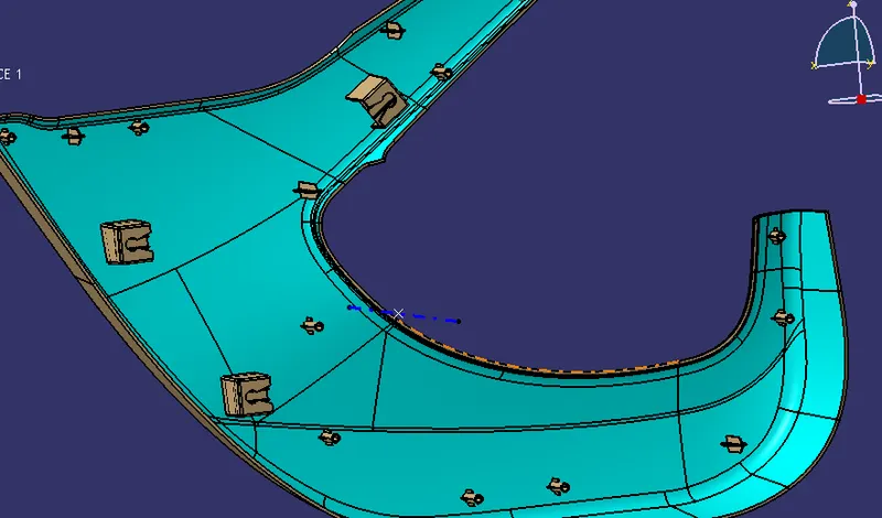
LOCATOR HEAT STAKES PUSHPIN & FLANGE
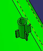
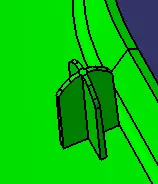
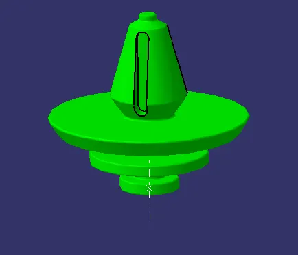
Create a flange for attachment of heat stakes and locators at lower substrate
WEIGHT OF THE COMPONENT
- Apply material plastic to the product
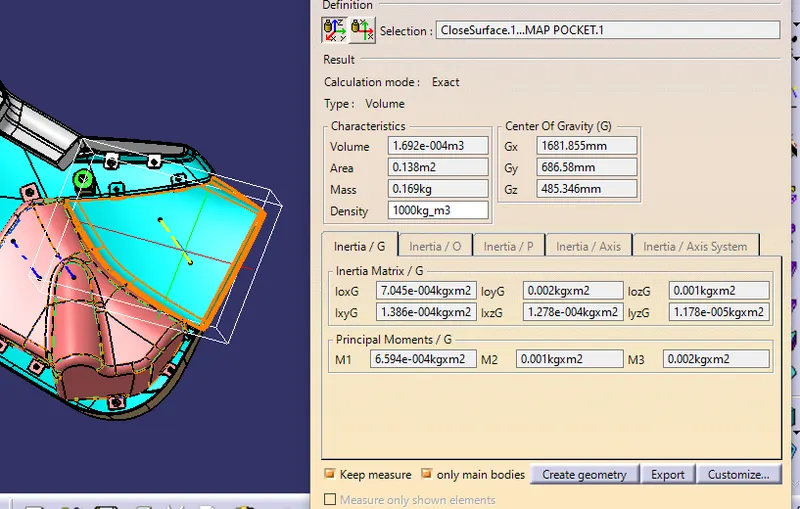
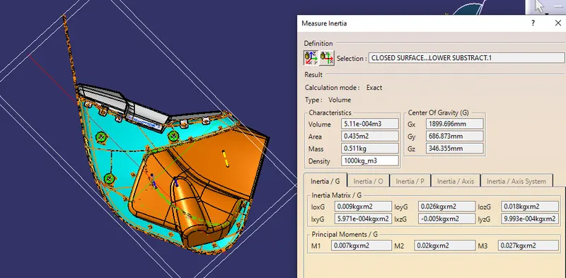
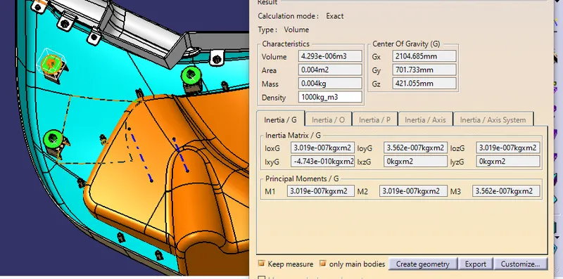
- Use the measure command to calculate the weight of the product
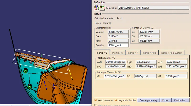
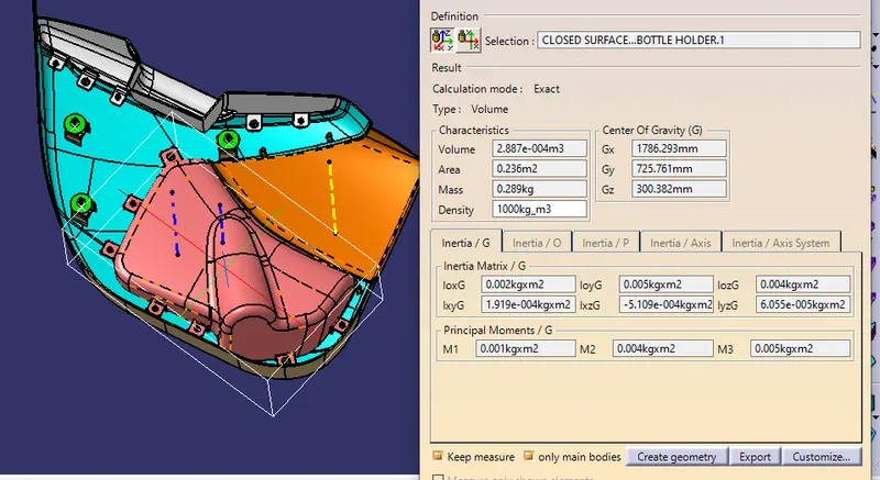
CALCULATION
Lower substrate=0.511kg
Bottle holder=0.289kg
Armrest =0.144kg
Map Pocket=0.169kg
Push Pin=0.004*3=0.012
The total weight of the product is =1.125kg
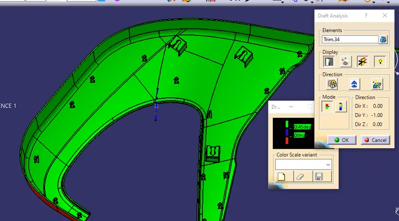
DRAFT ANALYSIS REPORT OF LOWER SUBSTRATE
DRAFT ANALYSIS REPORT OF BOTTLE HOLDER
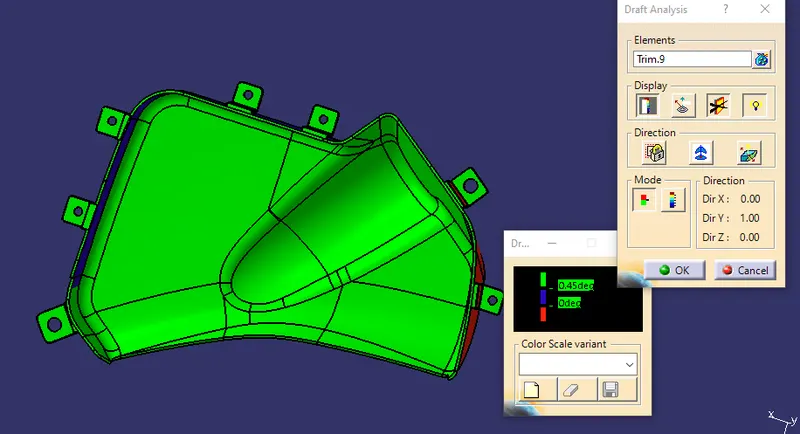
DRAFT ANALYSIS REPORT OF ARM REST
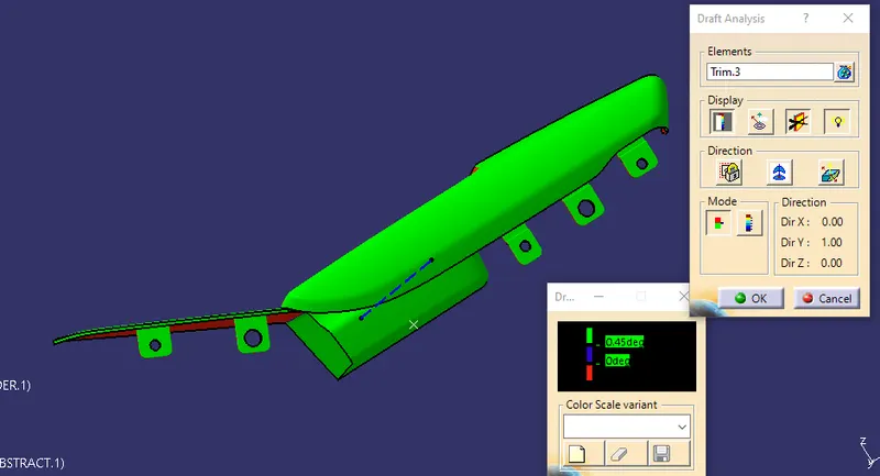
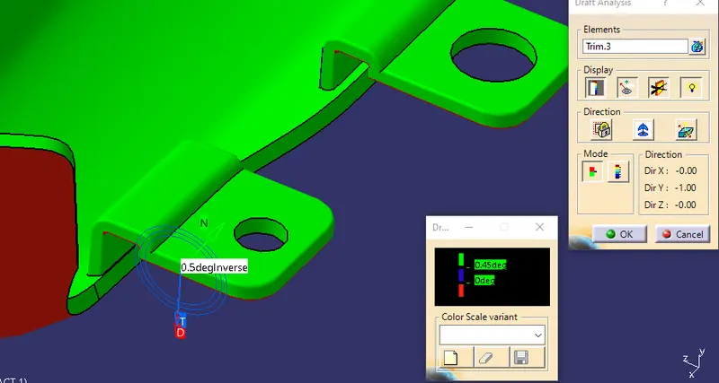
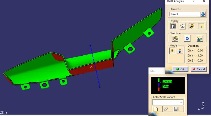
DRAFT ANALYSIS REPORT OF MAP POCKET
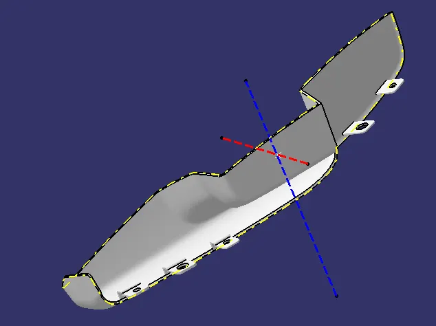
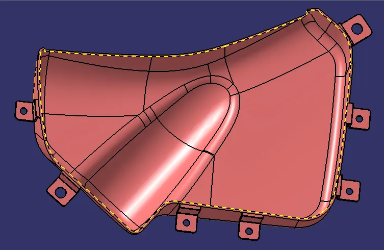
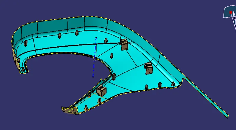
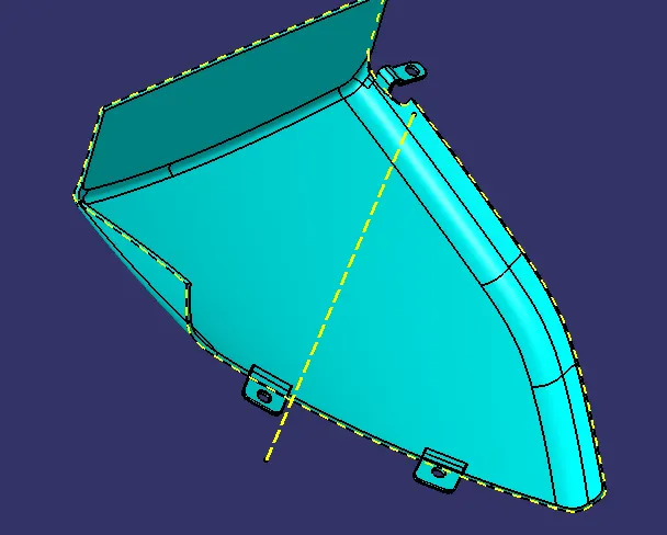
CREATION OF PARTING LINE
The parting line is used to the differentiate between core and cavity
NOTE = THE PARTING LINE BELOW IS CREATED WITHOUT ATTACHMENT
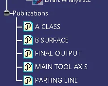
TREE STRUCTURE
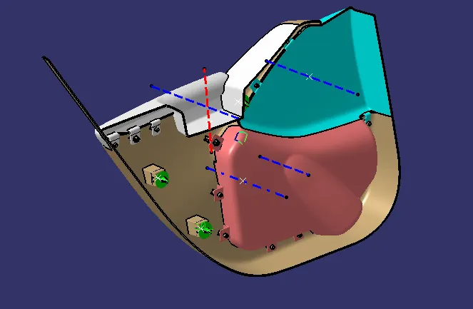
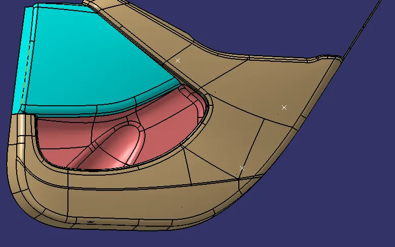
FINAL OBJECT
CONCLUSION
Thus the door interior part has been created from the inputs of class A surface along with the master section by following the design rules followed in tier 1 and OEM industries in catia v5