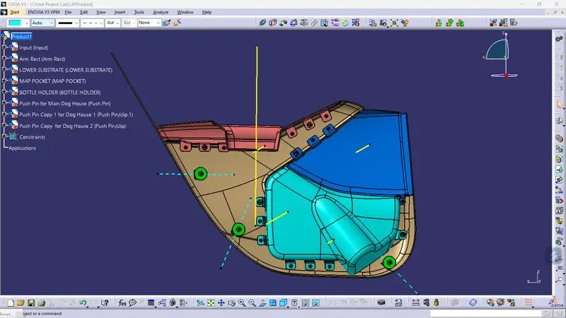
Final project - Lower Substrate Door Trim
1. Aim
To create the Lower Substrate Door Trim with Master Section and Class A Surface as an input. Design rules should be followed while creating the B side features. The mounting features should be created as per the guidelines and with the master Section.
2. Procedure
This Lower Substrate Door Trim is consists of 4 Parts and they are
- Arm Rest
- Map Pocket
- Bottle Holder
- Lower Substrate
As an input, Class A surface of this parts have been given. With the reference of Master Section, these Class A Surface's will be thickened seperately as an individual part. And finally these thickened Surface's will be assembled together with the Engineering features to form the Lower Substrate Door Trim.
Work Flow Pattern for the conversion of Thickened Surface;
- Creation of Tooling Axis
- Creation of Class B Surface
- Creation of Class C Surface
- Creation of Solid Component
As for the Engineering Features, Heat Stakes, Locators and Dog House with an push clip will be designed in the Lower Substrate part. And for the Mounting Features, Flanges will be designed in the Arm Rest, Map Pocket and Bottle Holder. The Lower Substrate part will act as the base where the Arm Rest, Map Pocket and Bottle Holder parts are gonna mounted together to form the final Lower Substrate Door Trim.
Work Flow Pattern for the B Side features
- Creation of Heat Stakes, Locators and Dog House at Lower Substrate.
- Creation of Flanges at Arm Rest, Map Pocket and Bottle Holder.
3. Conversion of Surface's into part:
3.1 Arm Rest:
3.1.1 Class A Surface Check
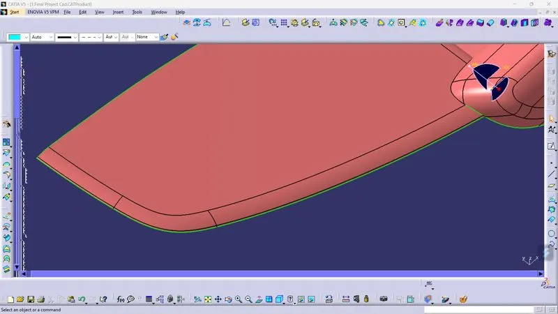
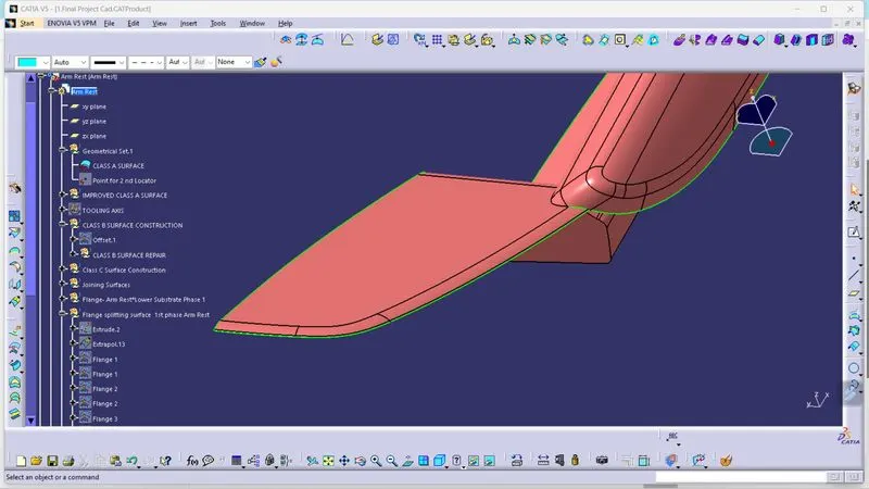
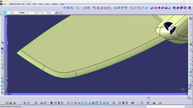
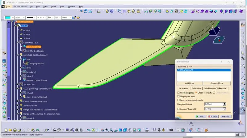
The Class A Surface which was provided as an input has an open boundary. As an Plastic Part Designer it is not allowed to do any changes in class A Surface, but after consulting this issue with the Technical Support Engineer, it is made an exception and allowed to modify a little, since the Class A Surface itself has some issues. So, For this Class A the Merging distance used for the Surface's was 0.08mm and along with this a curvy edge section was also removed becuase, while offseting the Class A Surface, these curvy edge surface's were not offseted and since it were in the edge they cannot be able to recreated.
Class A Surface with defect:
Improved Class A Surface:
3.1.2 Creation of Tooling Axis
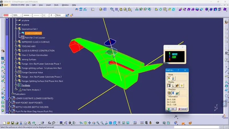
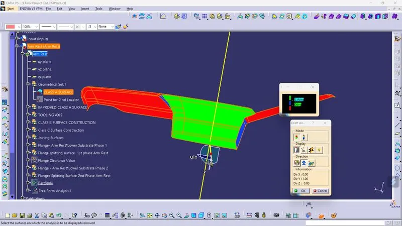
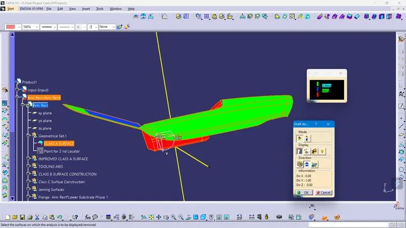
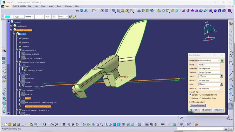
In Arm Rest there were two Tooling axis, where one acts as an and Main Tooling Axisthe other acts as an Side Core tooling Axis. This is because the Class A Surface has an curvy shape which cannot be able manufacture with a single Tooling Axis. The Main Tooling Axis was created with Direction to Y Method and the Side core Tooling Axis was created with Normal to Surface Method.
While Performing the draft analysis, Class A Surface clears at 3 degree of draft.
At Main Tooling Axis
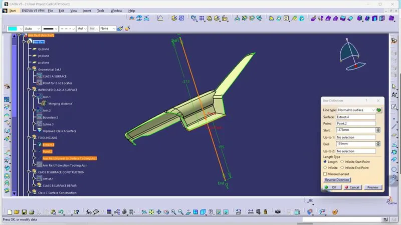
At Side Core Tooling Axis
3.1.3 Creation of Class B Surface
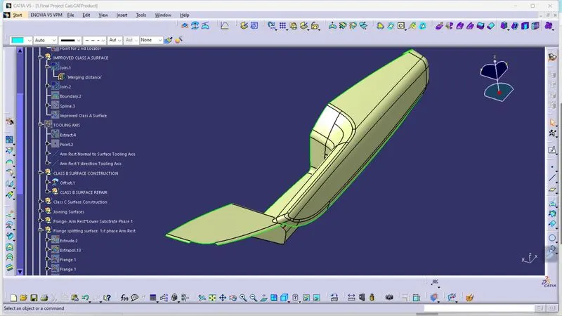
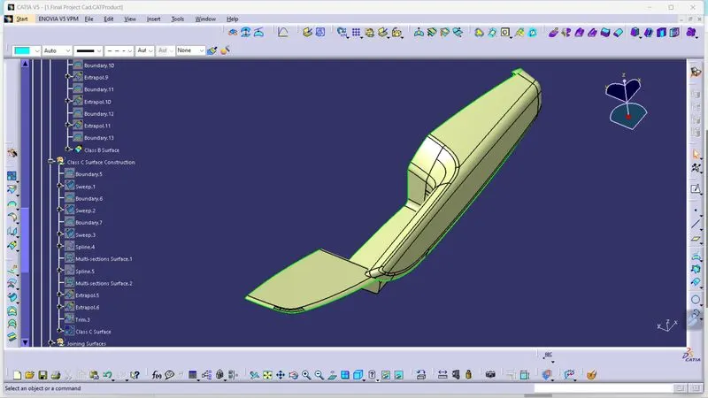
From the Master Section as reference, thickness of the part was taken as 2.5mm and it was offseted to it.
Offseted Class B surface:
Final Class B Surface:
3.1.4 Creation of Class C Surface
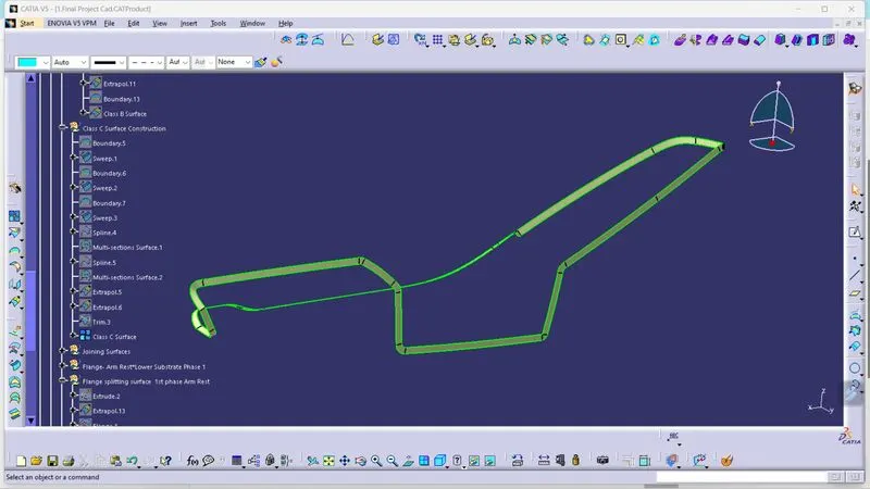
Class C Surface is nothing but the surface which joins Class A and B. For the Creation of Class C Surface. The surface which are perpendicular to the tooling axis was swept along reference to surface method with 90 degree angle and the surface which are parallel to the tooling axis was swept along draft direction method with 3 degree of angle.
Class C Surface:
3.1.5 Creation of Solid Component:
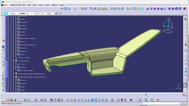
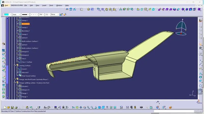
Now after the creation of all Class A, B and C Surface, it is time to assemble them together to create the closed Surface. For that, first the Class A and C surface were joined and trimmed with the Class B Surface to create the final Closed surface. With the Closed Surface in hand, it will be moved into Part Workbench to convert this Closed Suface to an Solid Part. With this Arm Rest Part was created.
Class A and C Surface:
Final Close Surface:
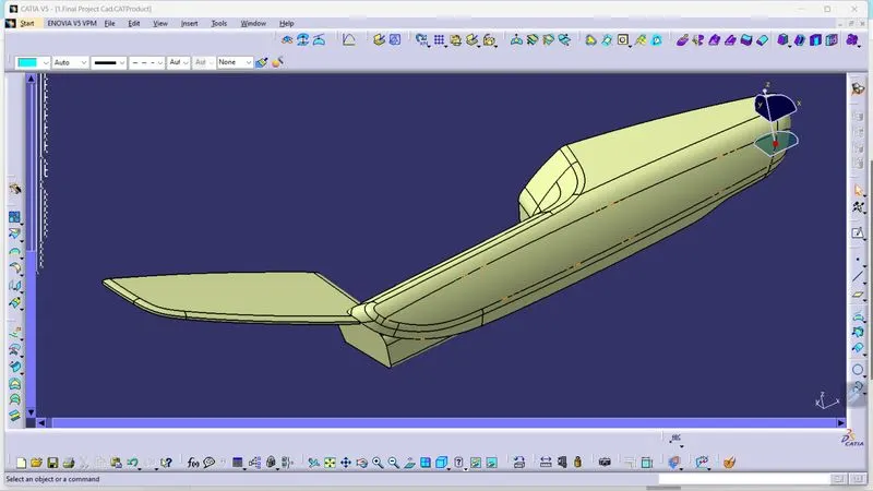
Thickened Part:
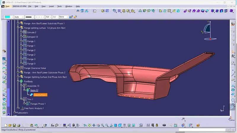
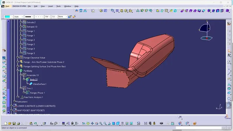
The Solid part creation of the Lower Substrate, Map Pocket and Bottle Holder will be mostly similar to the steps that were followed in the creation of Arm Rest's Solid Part with slight changes.
3.2 Map Pocket
3.2.1 Creation of Tooling Axis
For Map Pocket the Tooling Axis was created at Y direction.
Draft Analysis of Class A Surface at 2.9 degree:
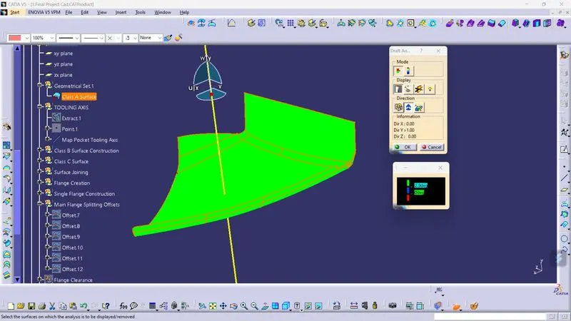
Tooling Axis:
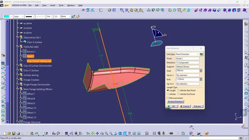
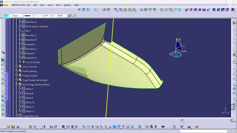
3.2.2 Creation of Class B Surface
From the Master Section as a reference, thickness of the part was taken and offseted into 2.5mm. All the edges of the Surfaces were extrapolated for 1 mm.
Offseted Class B surface:
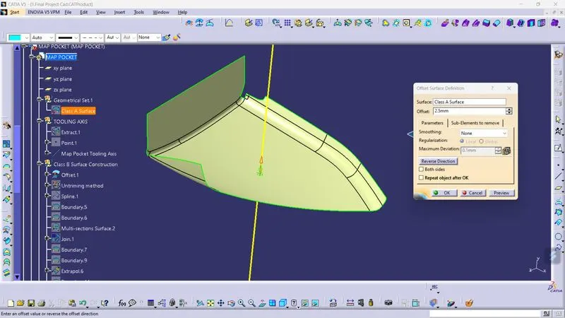
Final Class B Surface:
3.2.3 Creation of Class C Surface
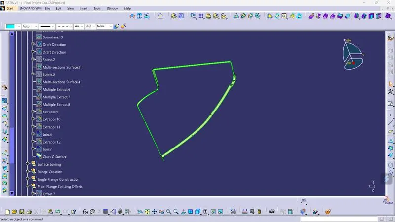
The surface which are perpendicular to the tooling axis was swept along reference to surface method at 90 degree angle and the surface which are parallel to the tooling axis was swept along draft direction method at 3 degree of angle.
Class C Surface:
3.2.4 Creation of Solid Component:
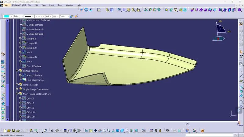
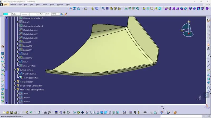
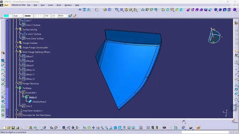
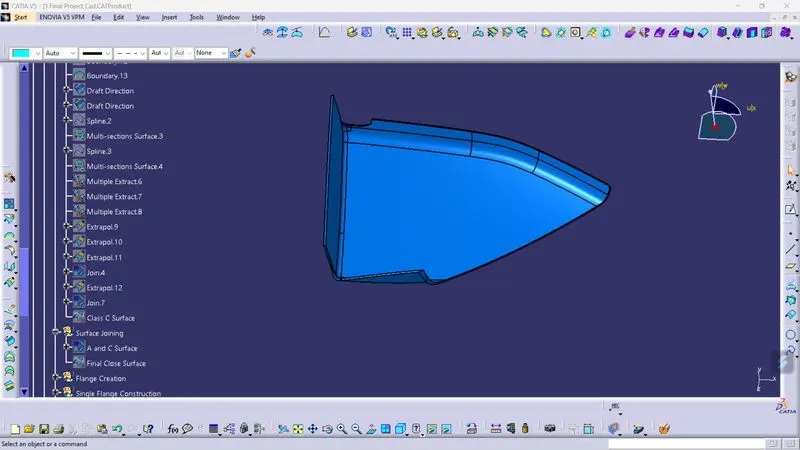
The Class A, B and C Surface's were assembled together to form an Closed surface and finally converted into an Solid Component.
Class A and C Surface:
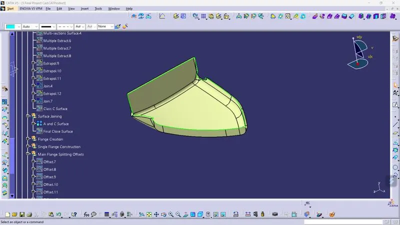
Final Close Surface:
Thickened Part:
3.3 Bottle Holder
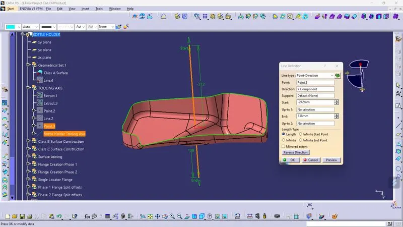
3.3.1 Creation of Tooling Axis
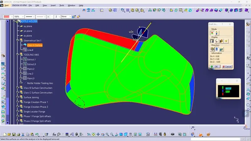
For Bottle Holder Tooling Axis was created in the Y Direction. The Class A Surface of this Bottle Holder is not clearing draft analysis since the Class A Surface itself wasn't drafted properly. With Consulting the Technical Support Engineer , it was said to proceed further with the same Class A Surface.
Draft Analysis of Class A Surface at 3 degree:
Tooling Axis:
3.3.2 Creation of Class B Surface
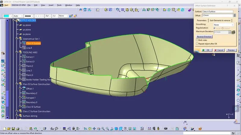
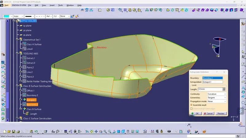
From the Master Section as a reference, thickness of the part was taken and offseted into 2.5mm.
Offseted Class B surface:
Final Class B Surface:
3.3.3 Creation of Class C Surface
The surface which are perpendicular to the tooling axis was swept along reference to surface method at 90 degree angle and the surface which are parallel to the tooling axis was swept along draft direction method at 3 degree of angle.
Class C Surface:
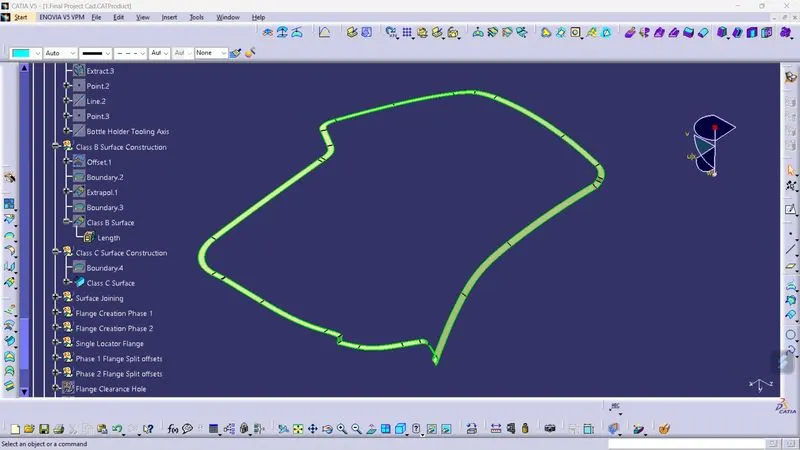
3.3.4 Creation of Solid Component:
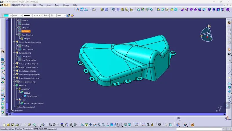
With Assembling the Class A, Class B and Class C surface , the closed surface was formed and later it was converted into Solid part in the Part Workbench
Class A and C Surface:
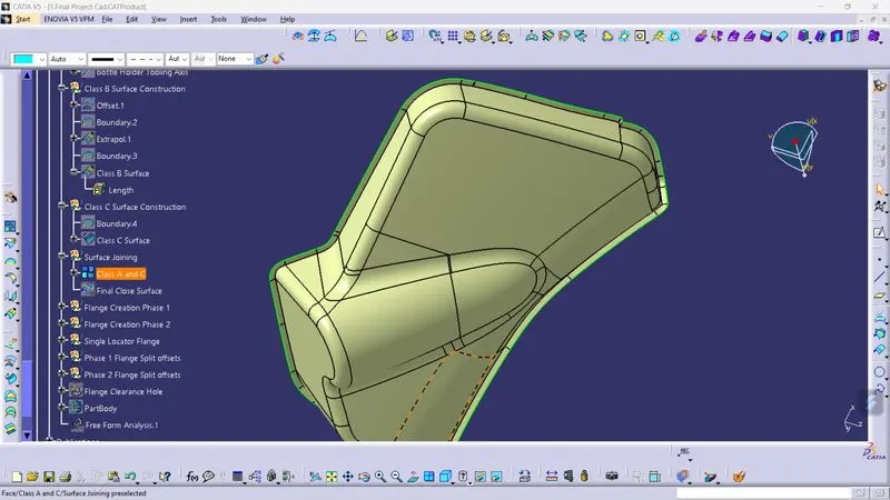
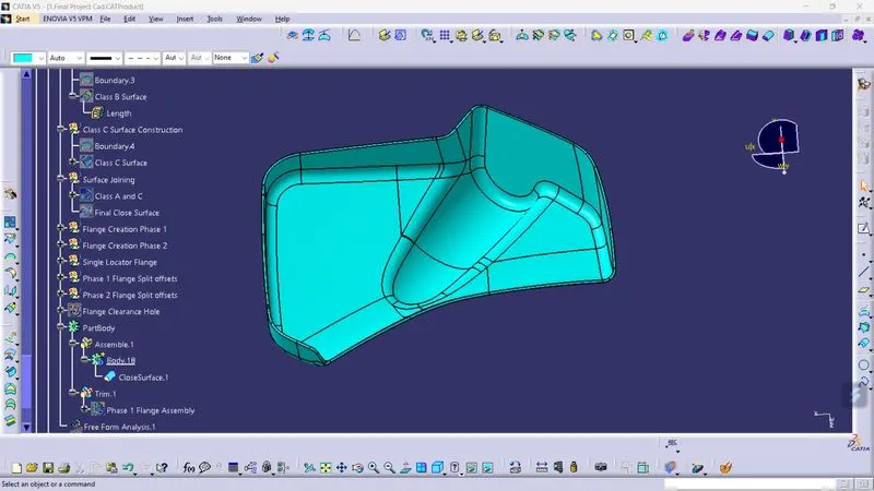
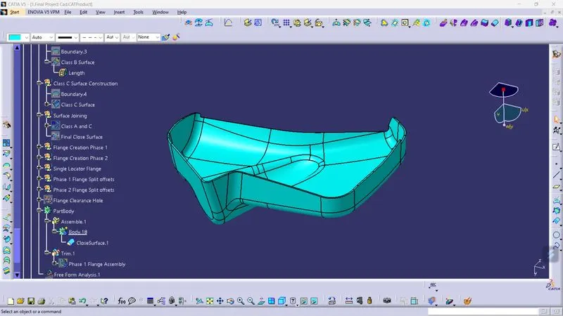
Final Close Surface:
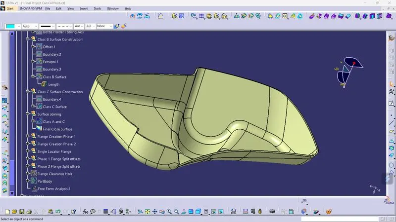
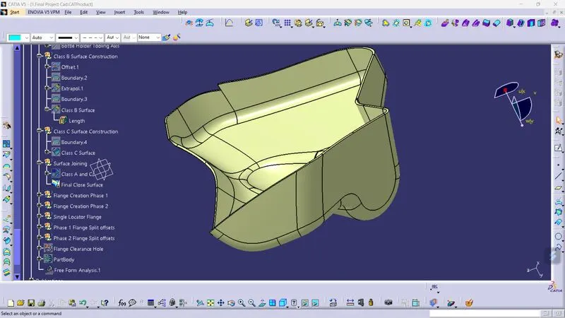
Thickened Part:
3.4 Lower Substrate
3.4.1 Creation of Tooling Axis
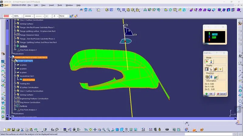
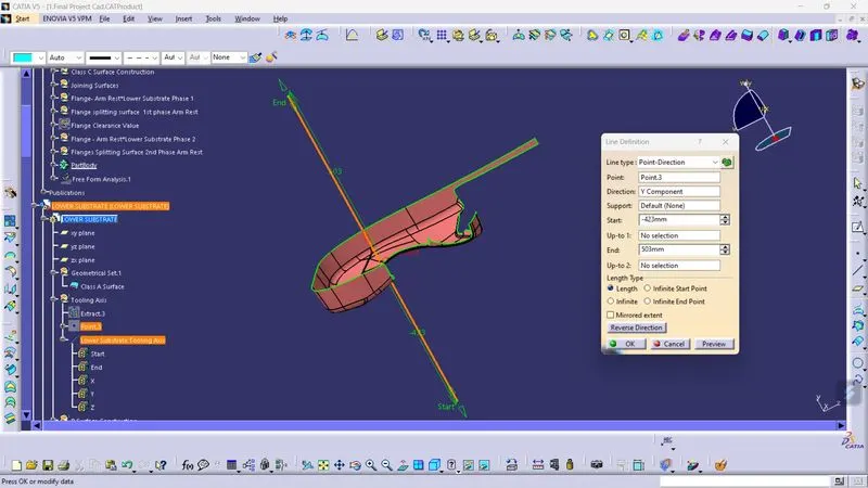
For Lower Substrate Tooling Axis was created in the Y Direction where all the surfaces were clearing at 3 degree of draft angle.
Draft Analysis of Class A Surface:
Tooling Axis:
3.4.2 Creation of Class B Surface
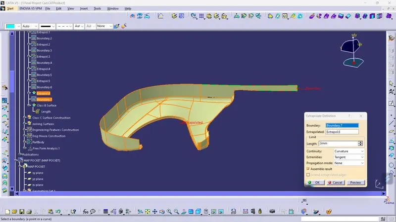
From the Master Section as a reference, thickness of the part was taken and offseted into 2.5mm.
Offseted Class B surface:
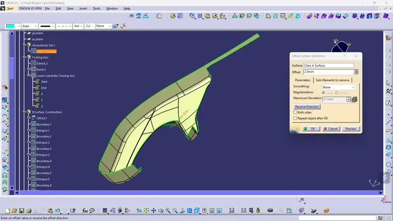
Final Class B Surface:
3.4.3 Creation of Class C Surface
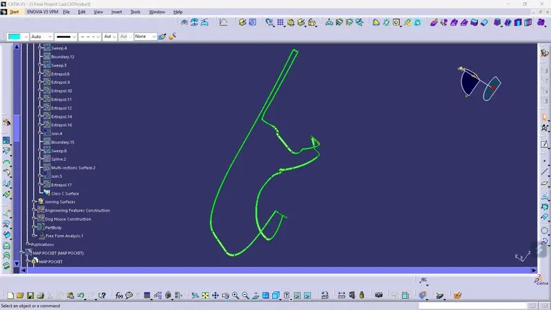
The surface which are perpendicular to the tooling axis was swept along reference to surface method at 90 degree angle and the surface which are parallel to the tooling axis was swept along draft direction method at 3 degree of angle.
Class C Surface:
3.4.4 Creation of Solid Component
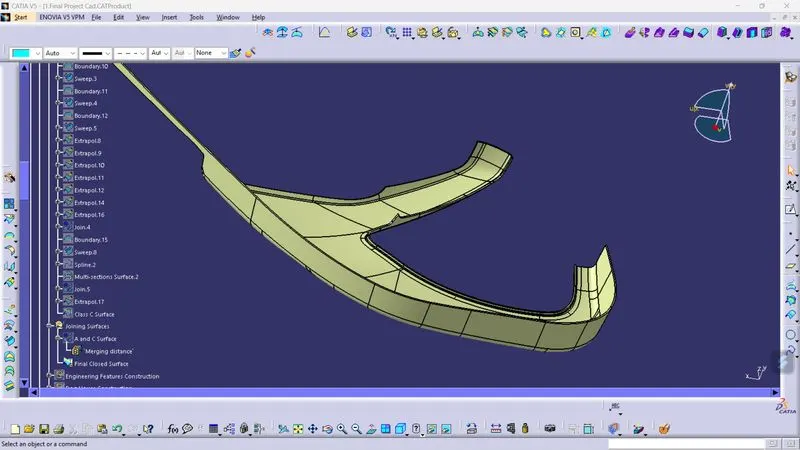
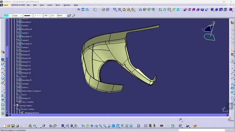
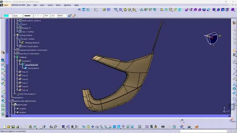
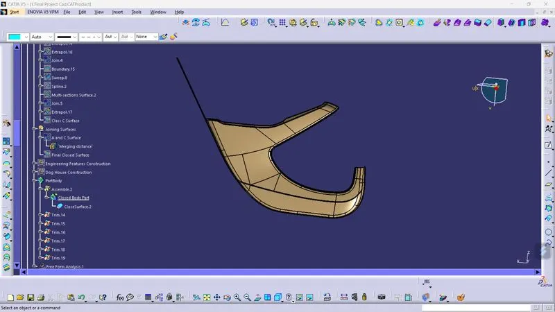
After the Creation of Class C Surface, Class A and C surface's were joined and trimmed along the Class B Surface to create the final Closed surface. Then in part workbench it was converted into Part by using Close Surface Tool. With this thickened part, the Lower Substrate part was created.
Class A and C Surface:
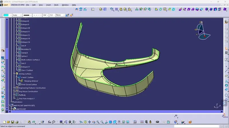
Final Close Surface:
Thickened Part:
4. Creation of B Side Features
4.1 Creation of Engineering Features:
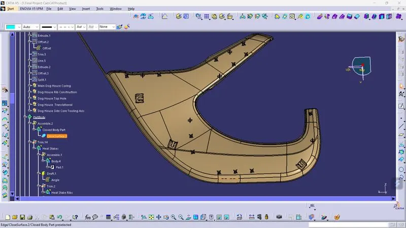
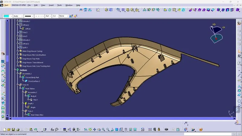
Firstly, the Engineering Features such as Heat Stakes, Locators and Dog House were planned to build in the Lower Substrate. For the Heat Stake design Master Section was followed. For all three features firstly the parent part alone were created later they were duplicated as result with link and translated to different Points.
The Design Constraints which was followed while designing them:
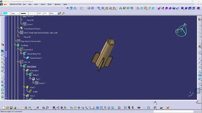
1. Heat Stakes
- Height - 25mm
- Inner Diameter - 4.5mm
- Outer Diameter - 7.5mm
- Draft Degree - 0.5
- Fillet Radius - 0.25mm
Design:
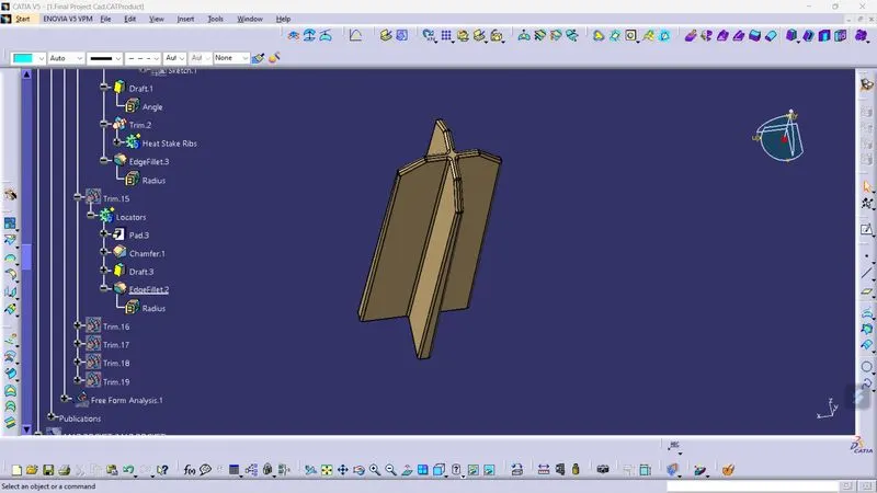
2. Locators
- Height - 30mm
- Draft Degree - 0.5 degree
- Fillet Radius - 0.25mm
- Length - 12*12
- Thickness at Tip - 0.776mm
Design:
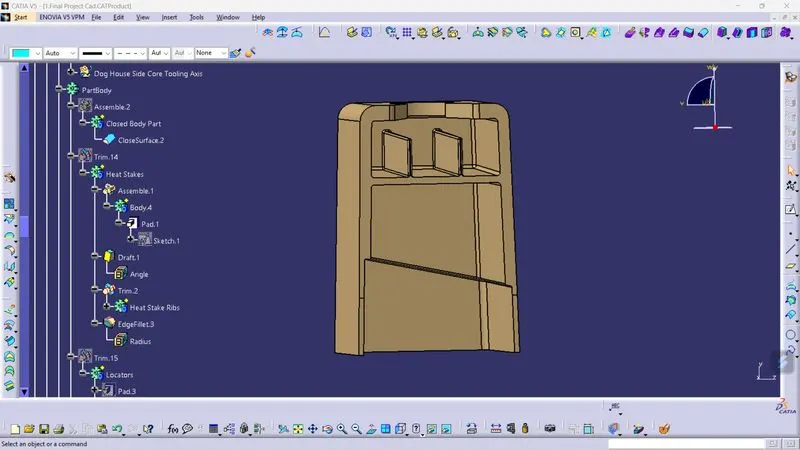
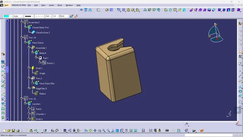
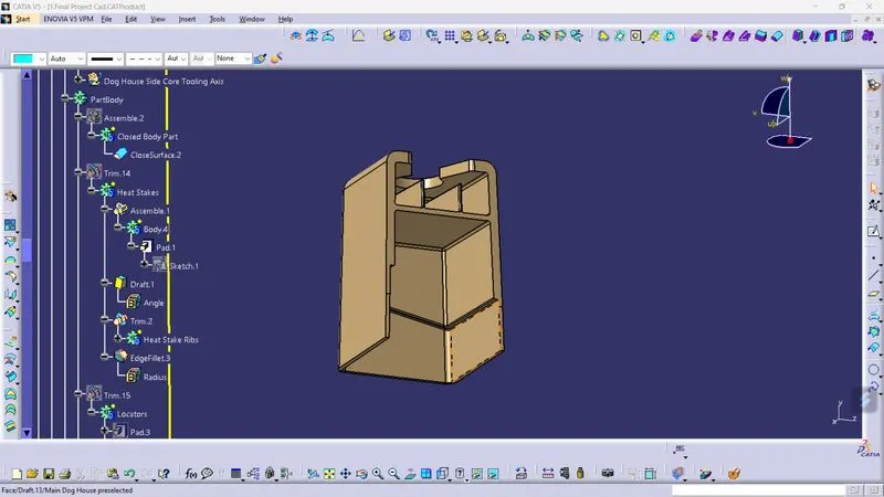
3. Dog House
- Height - 35mm
- Wall Thickness - 2mm
- Core Wall Thickness - 1mm
- Outer Wall Fillet Radius - 2.5mm
- Inner Wall Fillet Radius - 0.5mm
- Core Wall Fillet Radius - 0.25mm
- Main Tooling Axis Draft Degree - 1.49 degree
- Side Core Tooling Axis Draft Degree - 0.49 degree
- Push Pin Hole - Radius 5
Design:
4.2 Mounting Feature:
1. Flanges
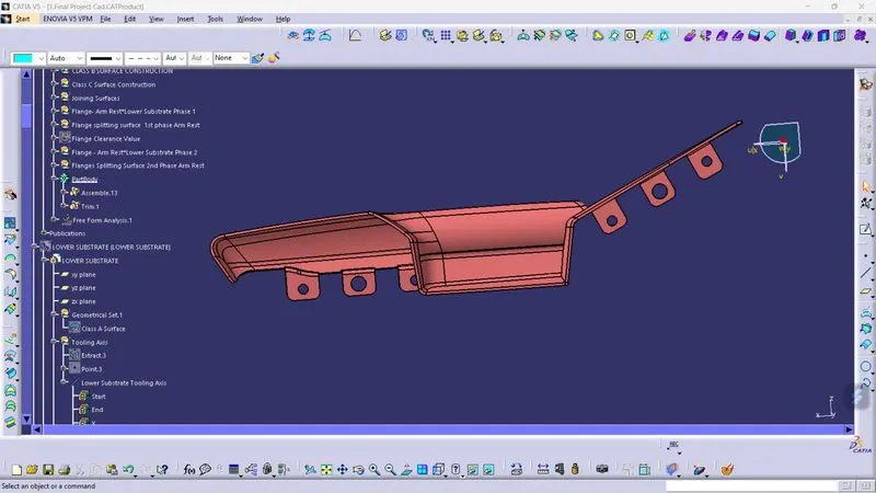
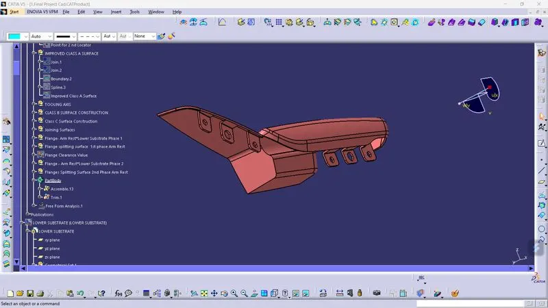
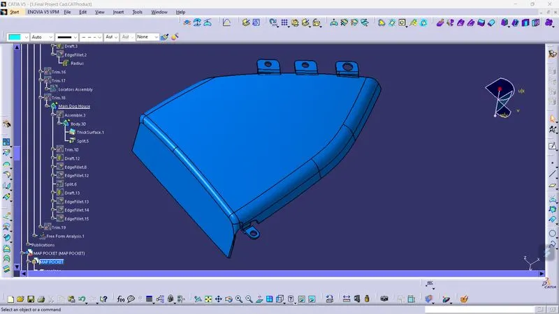
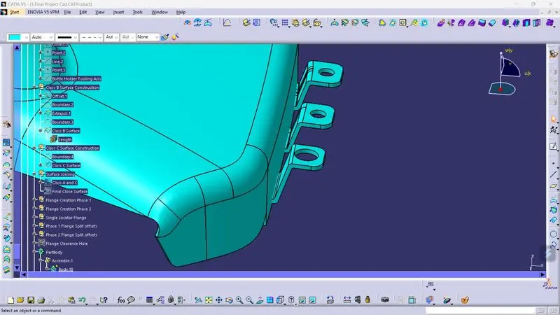
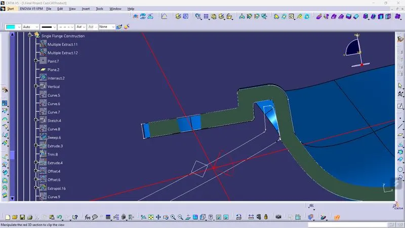
As an Mounting Feature Flanges were created on the three parts namely Arm Rest, Map Pocket and Bottle Holder. Geometry and Dimensional Constraints were taken from the Master Section as Reference. Also the holes in the Flanges for Heatstakes and Locators was provided with 0.5mm of clearance.
Flange Design in Arm Rest:
Flange Design in Map Pocket:
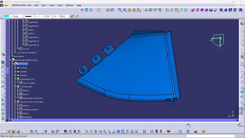
Flange Design in Bottle Holder:
3.6 Assembling of Engineering and Mounting Features
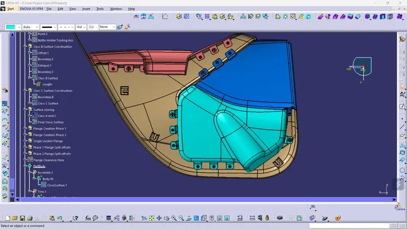
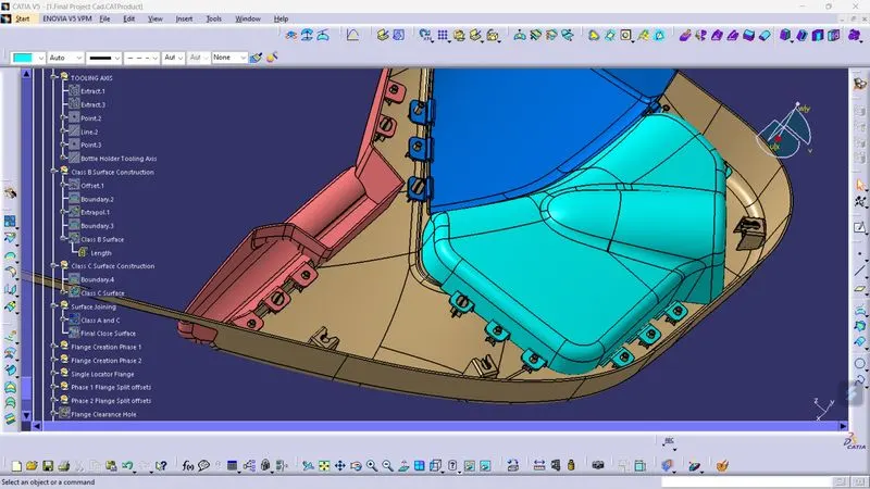
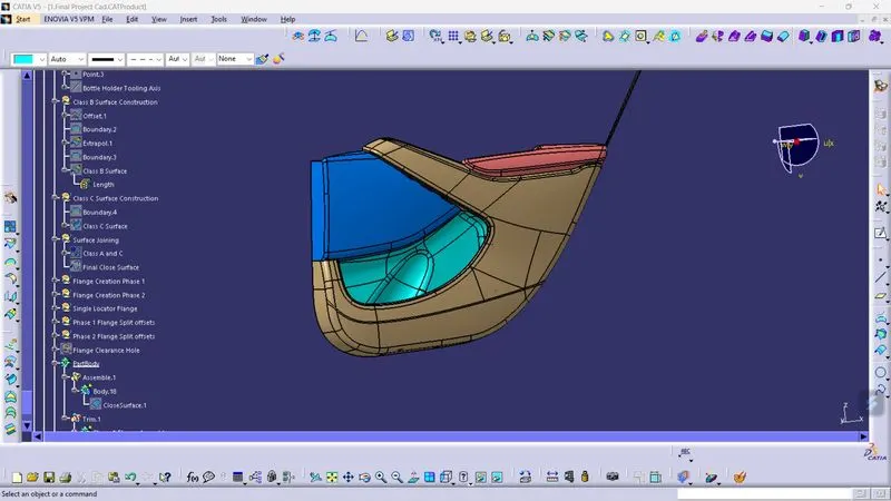
After all the Creation and Translation of the Engineering Features, Every Feature were assembled into their appropriate Part Body Using Boolean Operation Command 'Union Trim'.
Lower Substrate with Engineering Features:
Master Section Followed:
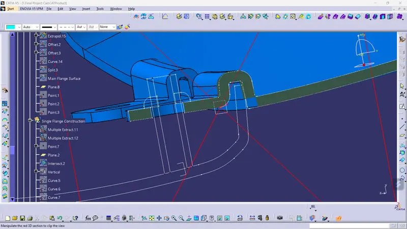
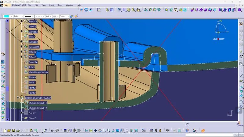
Assembled Product :
5. Draft Analysis
5.1 Draft Analysis of Solid Parts
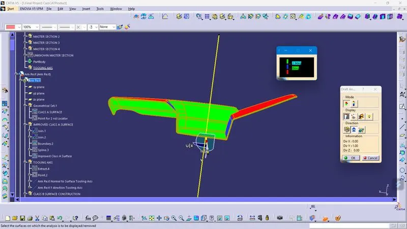
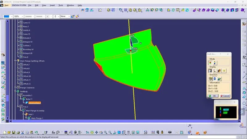
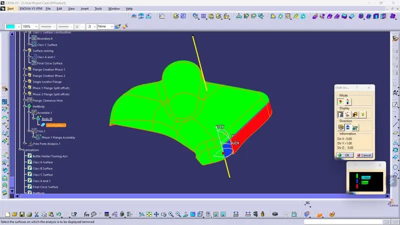
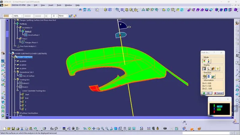
Draft Analysis of all the Solid Parts at 2.9 degree. The C surface for Map Pocket and LowerSubstrate were swept with Draft Direction at 3 degree angle. And in the final Part the wall are clearing the draft Analysis at 2.7 degree.
5.1.1 Arm Rest
- Main Tooling Axis
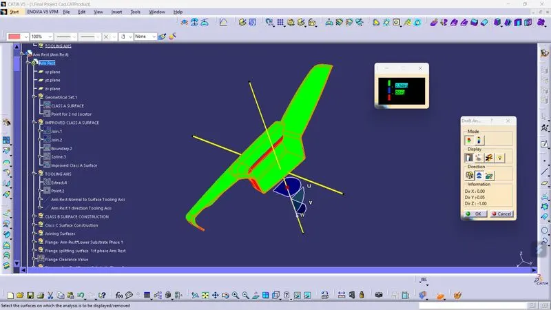
- Side Core Tooling Axis
5.1.2 Map Pocket
5.1.3 Bottle Holder
5.1.4 Lower Substrate
5.2 Draft Analysis on Engineering Features
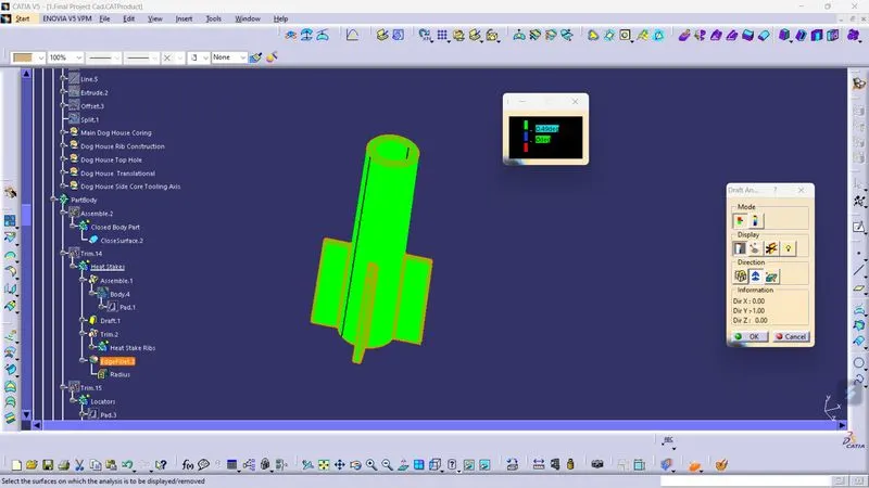
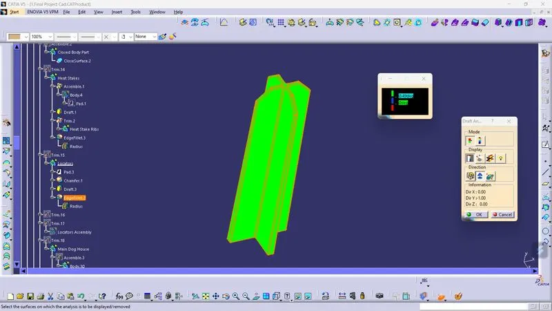
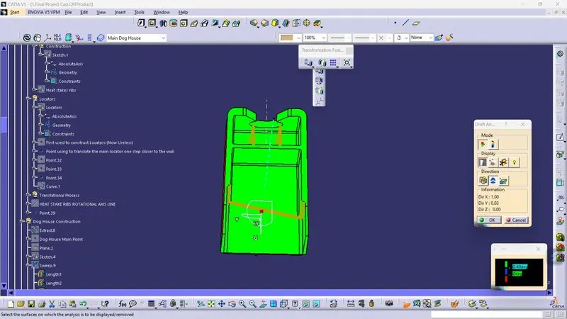
Draft Analysis of Engineering Features at 0.49 degree
5.2.1 Heat Stakes
5.2.2 Locators
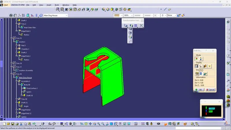
5.2.3 Dog House
- Main Tooling Axis at 1.49 draft degree
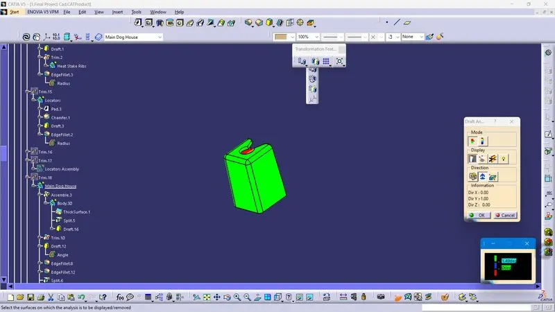
- Side Core Tooling Axis at 0.49 draft degree
5.3 Draft Analysis on Mounting Features
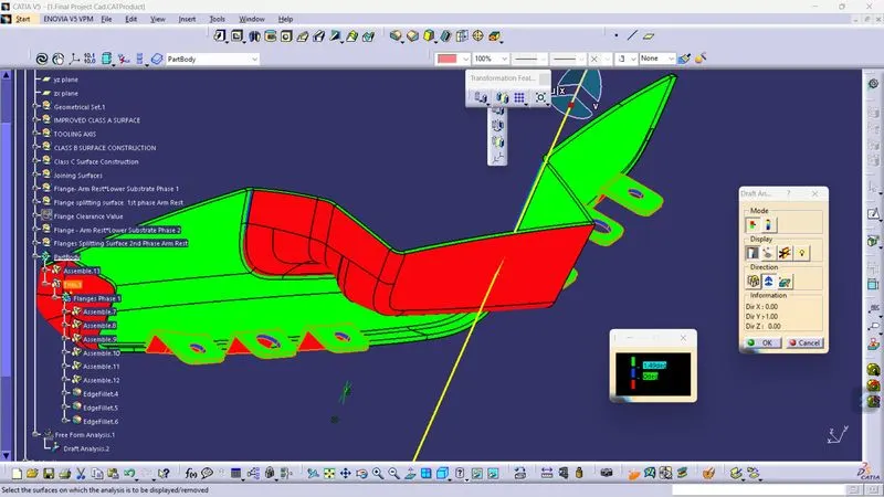
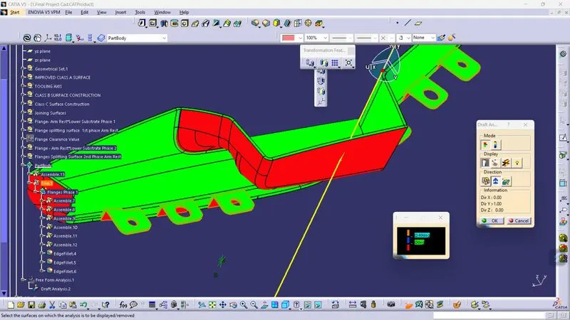
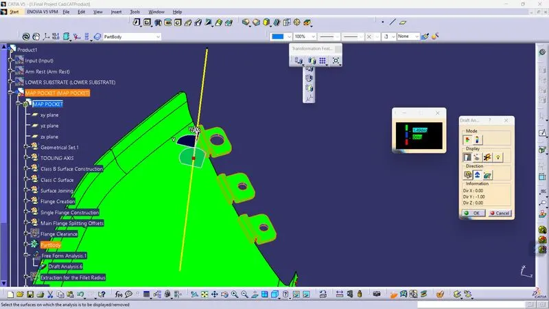
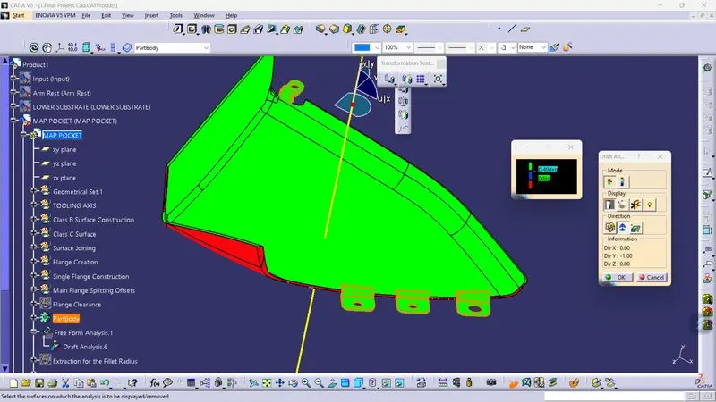
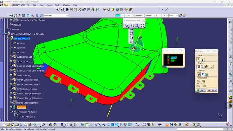
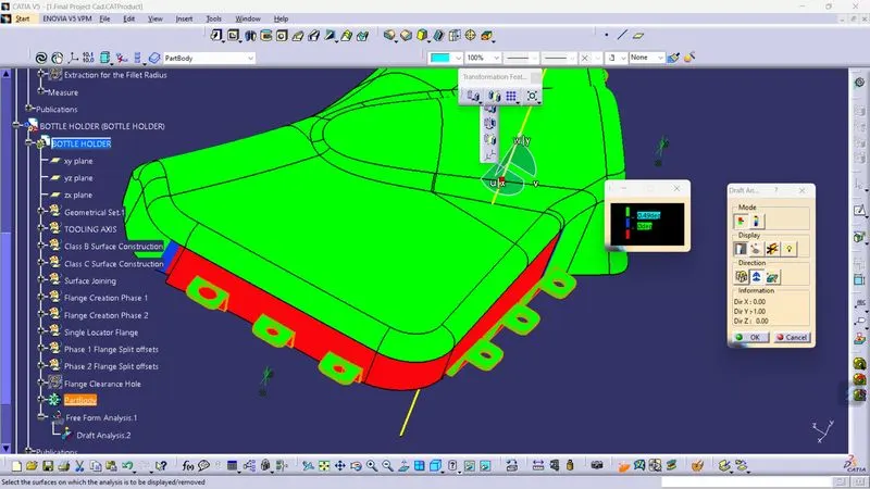
For the Flanges, 1.5 degree of draft angle was provided and its hole has 0.5 degree of draft angle.(0.5 is the clearance value that given to the Holes that putted on the Flanges for the Entry of Heat Stakes and Locators)
5.3.1 Arm Rest with Flange
- At 1.49 degree
- At 0.49 degree
5.3.2 Map Pocket with Flange
- At 1.49 degree
- At 0.49 degree
5.3.3 Bottle Holder with Flange
- At 1.49 degree
- At 0.49 degree
6. Conclusion
With the given Class A surface as an input, Tooling Axis, Class B Surface , Class C Surface and all the Engineering Features were Created. Also both the Final Component and Engineering Features were clearing the Draft Analysis.
Final Product: