Week 11 - Final project
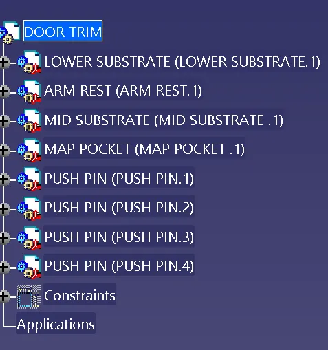
DOOR TRIM ASSEMBLY:
PARTS:
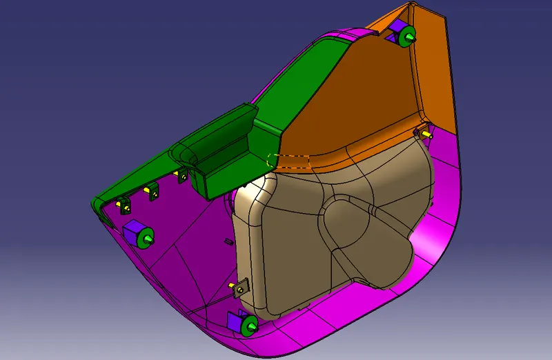
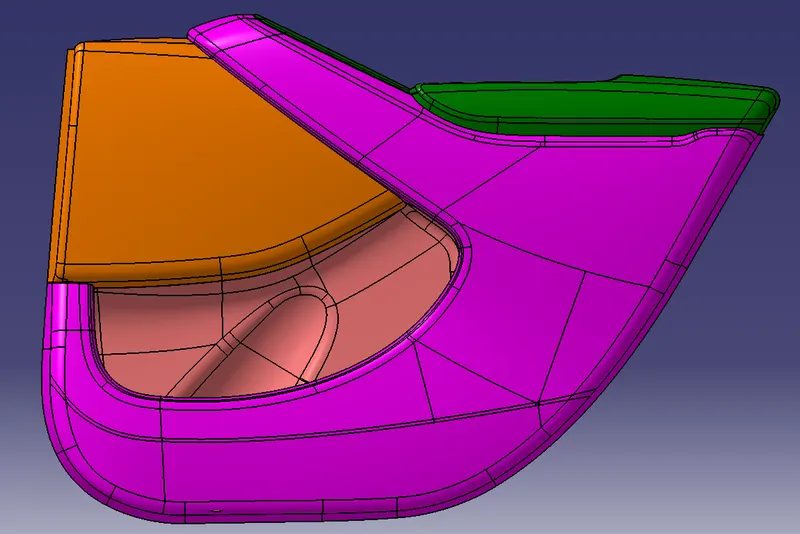
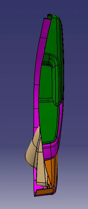
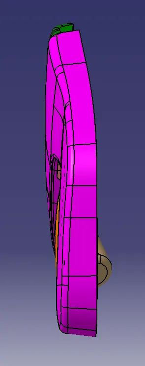
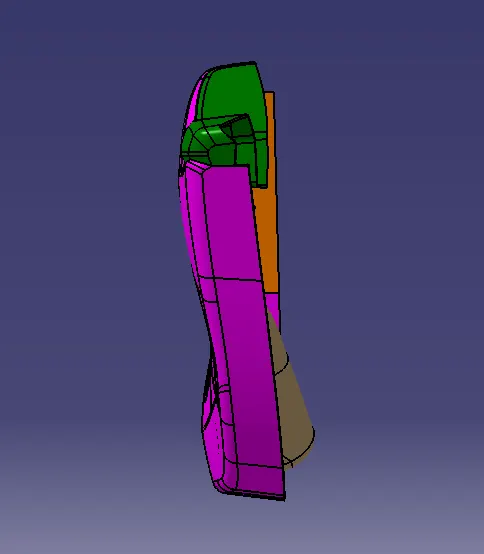
| S.NO. | PART NAME | REPRESENTAION COLOR | QUANTITY |
| 1 | LOWER SUBSTRATE | Pink | 1 |
| 2 | ARM REST | Green | 1 |
| 3 | MID SUBSTRATE | Orange | 1 |
| 4 | MAP POCKET | Beige | 1 |
| 5 | PUSHCLIPS | Light Green | 2 |
ASSEMBLY TREE STRUCTURE:
FRONT & BACK VIEW:
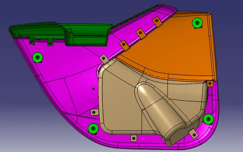
TOP & BOTTOM VIEW:
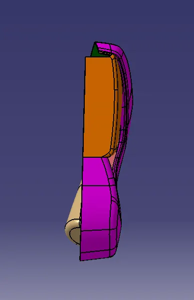
SIDE VIEWS:
TOOLING AXIS CREATION:
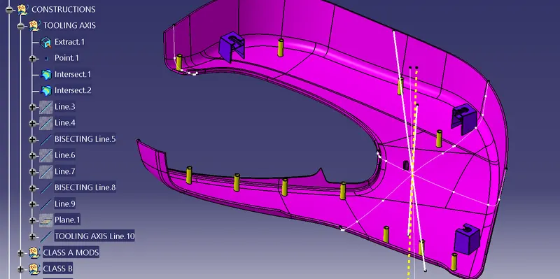
1. LOWER SUBSTRATE:
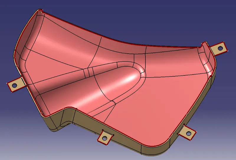
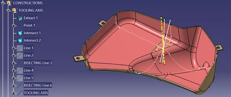
As seen below Extract from class A is taken and its centroid is obtained through which TOOLING AXIS will be passing.
Axis system is introduced for creating intersect in other two direction.
Projection Lines are created on steepest surface with respect to draft angle for each intersect.
The lines obtained are then bisected to form BISECTING lines (thick white lines) as mentioned in tree structure.
Further, these BISECTING lines are bisected to form the TOOLING AXIS (dotted yellow).
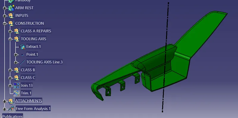
2. ARM REST:
As seen below Extract from class A is taken and its centroid is obtained through which TOOLING AXIS will be passing.
TOOLING AXIS (dotted black) is created in direction normal to surface.
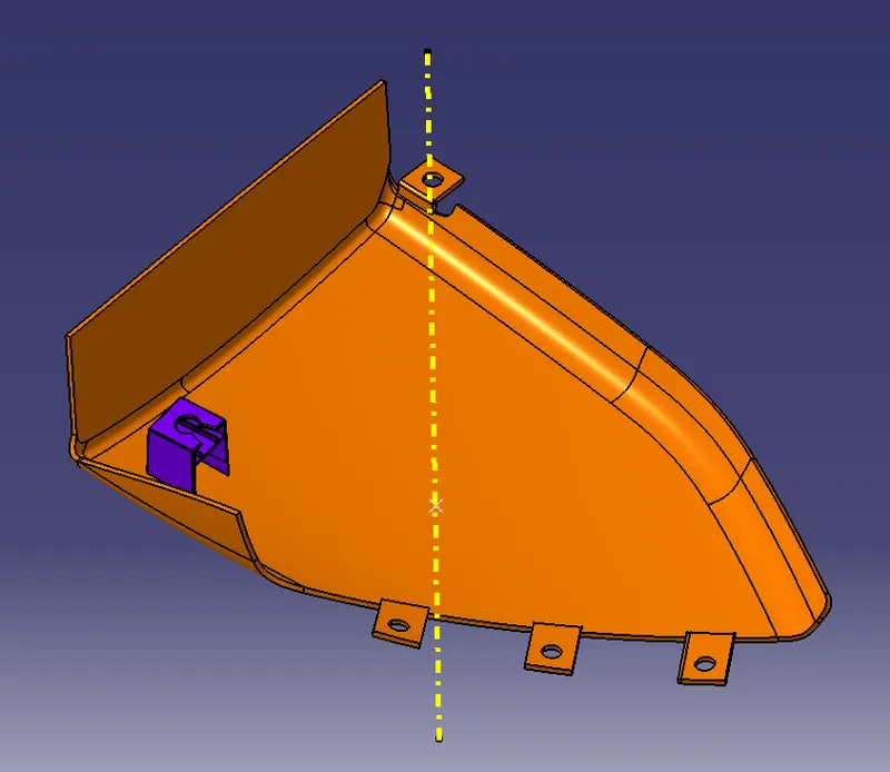
3. MID SUBSTRATE:
As seen below Extract from class A is taken and its centroid is obtained through which TOOLING AXIS will be passing.
TOOLING AXIS Line is created parallel to the lower substrate tooling axis because both uses identical doghouse structures and also clears draft analysis for class A as well as class B surface for both structures.
4. MAP POCKET:
As seen below Extract from class A is taken and its centroid is obtained through which TOOLING AXIS will be passing.
Axis system is introduced for creating intersect in other two direction.
Projection Lines are created on steepest surface with respect to draft angle for each intersect.
The lines obtained are then bisected to form BISECTING lines (thick white lines) as mentioned in tree structure.
Further, these BISECTING lines are bisected to form the TOOLING AXIS (dotted yellow).
DRAFT ANALYSIS:
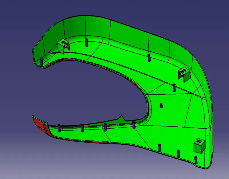
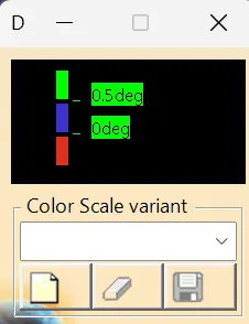
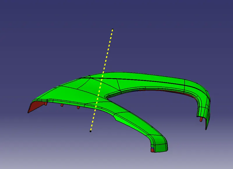
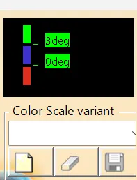
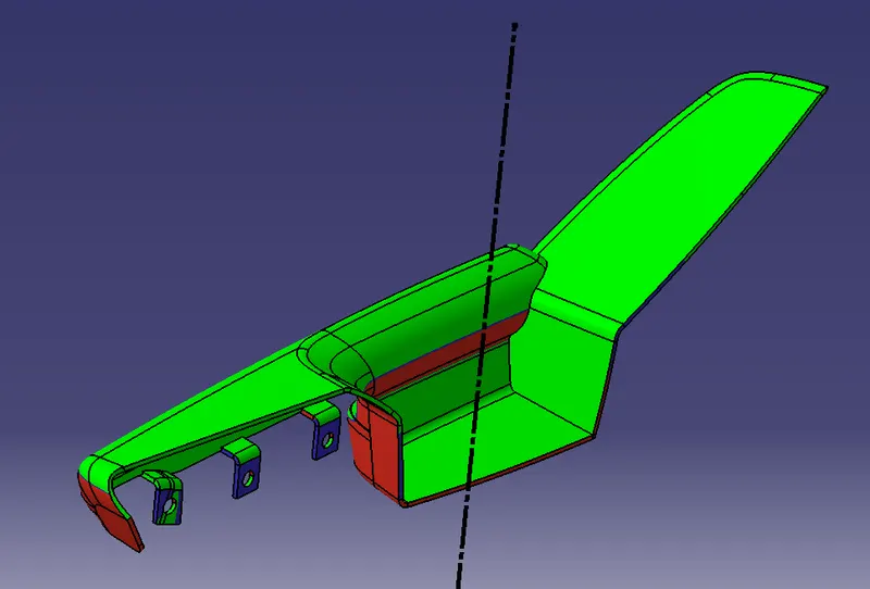
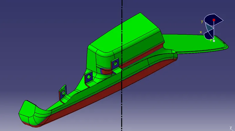
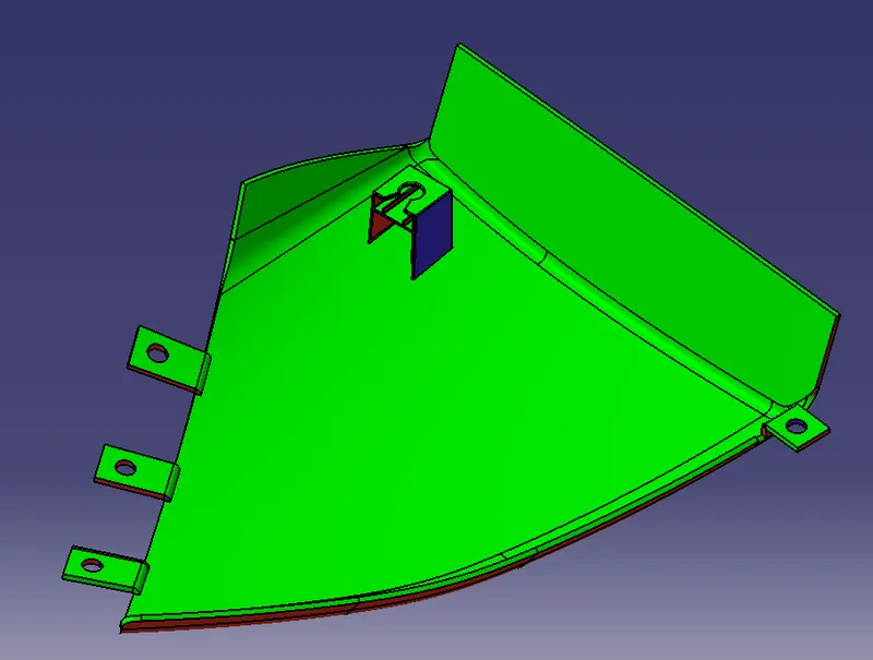
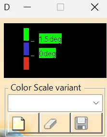
GREEN: shows Surfaces that are over the minimum draft angle given.
BLUE: shows Surfaces that are below the minimum draft angle given but above 0deg.
RED: shows Surfaces that are below the 0deg draft angle.
1. LOWER SUBSTRATE:
Minimum Draft Angle: 0.5deg because of HEAT STAKES and locator present on CLASS B surface
Minimum Draft Angle: 3deg at class A surface as it is free from any attachments.
2. ARM REST:
Minimum Draft Angle: 3deg
3. MID SUBSTRATE:
Minimum Draft Angle: 3deg on CLASS A surface.
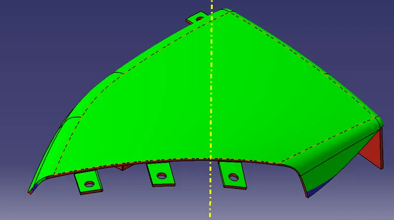
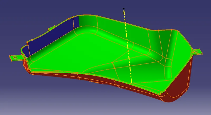
Minimum Draft Angle: 1.5 deg on CLASS B surface due to presence of DOGHOUSE.
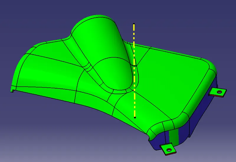
4. MAP POCKET:
Minimum Draft Angle: 3deg
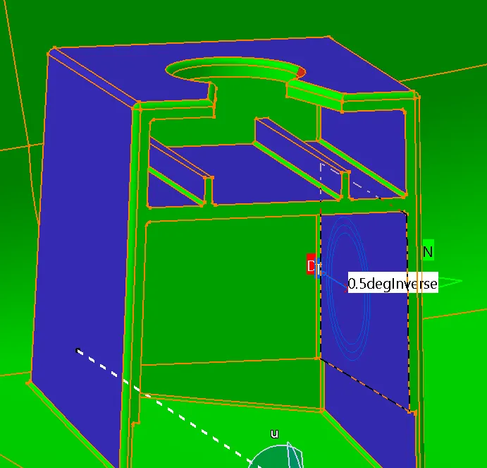
5. DOGHOUSE:
Minimum Draft Angle: 0.5deg
Situated on LOWER SUBSTRATE and MID SUBSTRATE parts.
PARTING LINES:
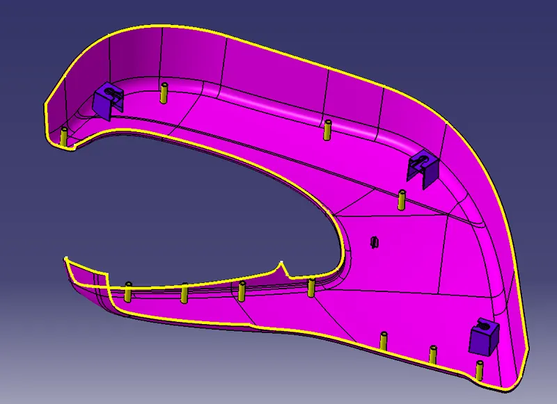
1. LOWER SUBSTRATE:
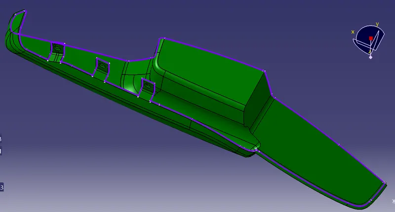
2. ARM REST:
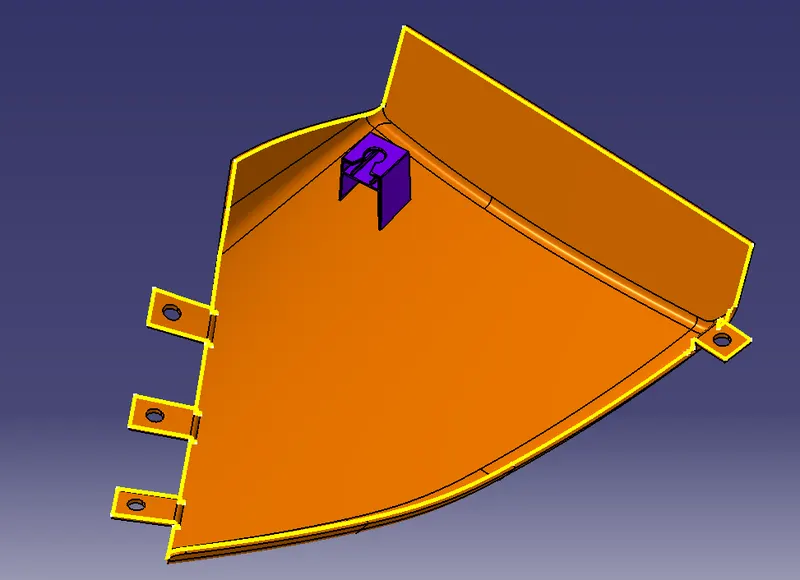
3. MID SUBSTRATE:
4. MAP POCKET: