Week 11 - Final project
Aim - To design the car door Inner Panel with reference to given Class-A surface by using given mastersection, creating attachment features and performing draft analysis to check the manufacturing feasibility of the component by using software CATIA V5.
Objective -
- Ensure Proper Tree Structure.
- Geometrical sets should have a proper name based on the sketches present inside them.
- All the sketches should be created under the Geometrical set.
- Use the Close Surface feature to make a solid body from the surface.
- To publish the Tooling Axis, Class A, Class B ,Final Product.
- Other attachment features were also created for assembly of the different components of door trim
Design Methodology -
- Class-A suface was extracted from the given surface.
- Determining the tooling axis for the A pillar design
- Creation of class B surface.
- Creation of class C surface.
- Join the class A, class B, and class c surfaces and ensure all the surfaces are closed surfaces.
- Use the Close Surface feature to make a solid body from the surface.
- Engineering features were created for attachment.
- Draft analyses of each component was performed to check the manufacturing feasibility.
Introduction -
The inner door panel is an aesthetic and functional component in a car, it is the interface between the car interior and the inner working of door. Inner door panel usually consists of armrest, map pocket, bottle holder, handle bar, other switches, upper and lower substrate, storage compartments, convenience (puddle) lights and locking mechanism. Nowdays door panel is made of plastic material like polypropylene, ABS etc. which helps in making lightweight and complicated shapes of door panels.
The manufacuring Process of plastic door panel is called Injection molding. In this manufacturing process the heated molten plastic material is injected into the mould between core and cavity and cooled down to form a solid plastic component.
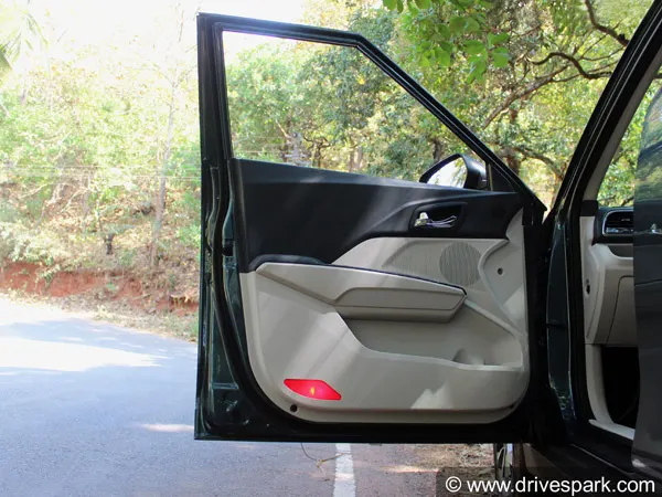
PROCEDURE
Given CLASS-A surface with Mastersection
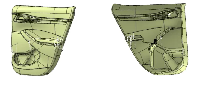
Components included in door panel
- Arm Rest
- Map Pocket
- Lower Substrate
- Bottle Holder
1.Arm Rest -
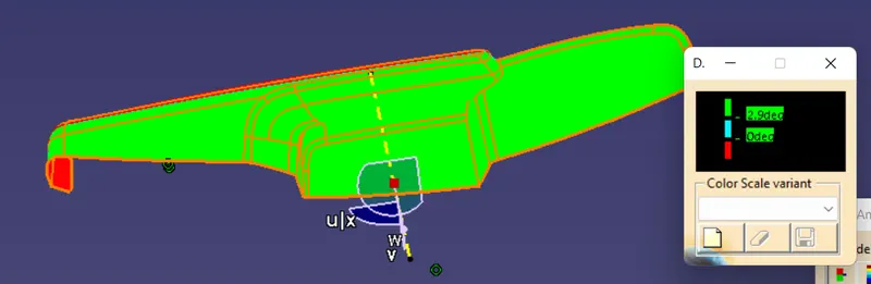
1.1.Tooling Axis - Generally 3 methods used to create the tooling axis.
- Normal to plane (Large surface avilable).
- Bisecting the line.
- Point and Direction.
For Arm Rest we have used bisecting line method to create main tooling axis and point and diresction for the side core tolling axis and Class A surface clears in draft analysis.
1.2.Class B Surface -
To create the class B surface, offset the class A surface inside as per our thickness requirement (here the master section given and thickness is 2.5mm, so offseted the class A to 2.5 mm inside). Once the offset is created, we can observe some patches on the offset surface by taking the boundary for the offset surface, those patches are formed due to the fillets on the class A surface. We need to cover those patches with the help of the multi-section surfaces command by extracting the patch boundaries. Once all the patches on the offset are covered properly join all the patches with the offset surface, to get the replicated surface of the class A surface.
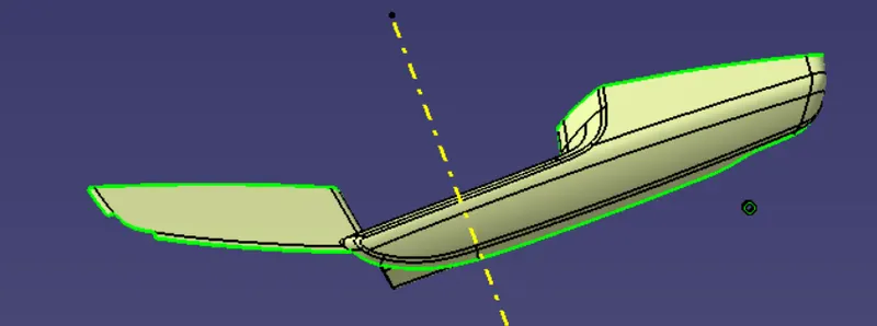
Fig. After Giving Offset
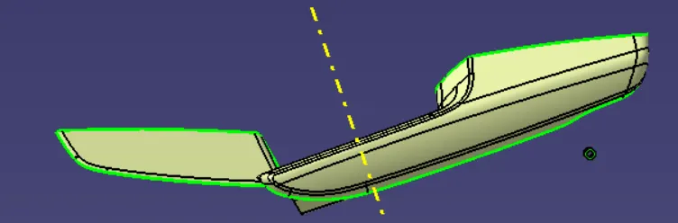
Fig. After Filling Patches
1.3.Creation of C Surface -
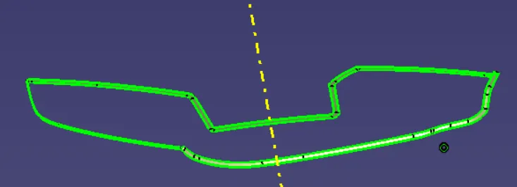
The edges of the Class-A surface are extracted using the multiple extracts and surface that are parallel to the main tooling axis are made with sweep draft angle 3 degree and surfaces that are perpendicular to the main tooling axis are made with sweep reference surface. At last join the all surfaces.
1.4.Final Trims -
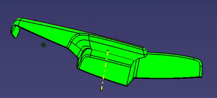
Joining the Surface A + Surface B + Surface C
1.5.Flanges-
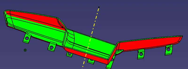
Flanges are the joining features that help to assemble different components. The mastersection was used to make flanges. After creating one flange axis to axis sytem was used to translate the flanges. The draft of 0.5 is given to the flanges. The gap between flanges should be 60-100 mm. Boolean operations were used to add attachment features into closed body.
2.Map Pocket -
2.1.Tooling Axis - Generally 3 methods used to create the tooling axis.
- Normal to plane (Large surface avilable).
- Bisecting the line.
- Point and Direction.
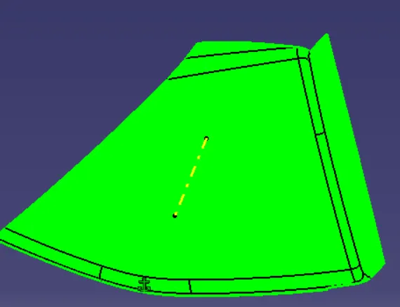
For Map Pocket normal to surface is used to create main tooling axis and Class A surface clears in draft analysis.
2.2.Class B Surface -
To create the class B surface, offset the class A surface inside as per our thickness requirement (here the master section given and thickness is 2.5mm, so offseted the class A to 2.5 mm inside). Once the offset is created, we can observe some patches on the offset surface by taking the boundary for the offset surface, those patches are formed due to the fillets on the class A surface. We need to cover those patches with the help of the multi-section surfaces command by extracting the patch boundaries. Once all the patches on the offset are covered properly join all the patches with the offset surface, to get the replicated surface of the class A surface.
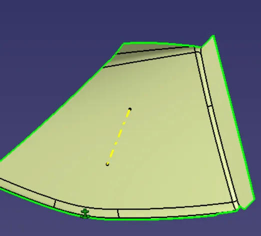
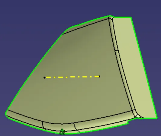
Fig.After Giving Offset Fig.After After Filling Patches
2.3.Creation of C Surface -
The edges of the Class-A surface are extracted using the multiple extracts and surface that are parallel to the main tooling axis are made with sweep draft angle 3 degree and surfaces that are perpendicular to the main tooling axis are made with sweep reference surface. At last join the all surfaces.
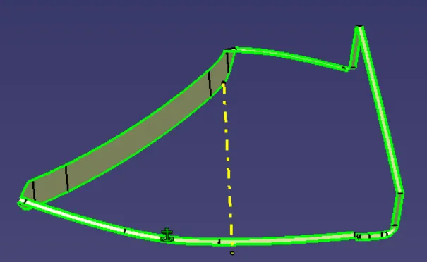
4.Final Trims -
Joining the Surface A + Surface B + Surface C and last Close surface.
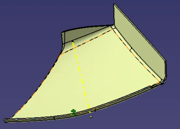
2.5.Flanges-
Flanges are the joining features that help to assemble different components. The mastersection was used to make flanges. After creating one flange axis to axis sytem was used to translate the flanges. The draft of 0.5 is given to the flanges. The gap between flanges should be 60-100 mm. Boolean operations were used to add attachment features into closed body.
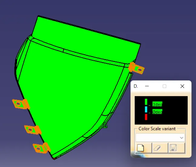
3.Lower Substrate -
3.1.Tooling Axis - Generally 3 methods used to create the tooling axis.
- Normal to plane (Large surface avilable).
- Bisecting the line.
- Point and Direction.
For A Lower Subsrtae Point and Direction is used to create main tooling axis and Class A surface clears in draft analysis.
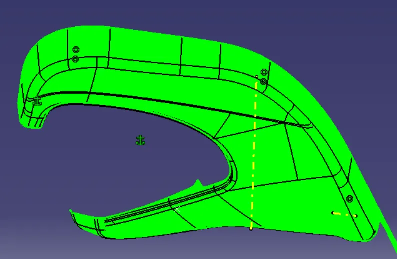
3.2.Class B Surface -
To create the class B surface, offset the class A surface inside as per our thickness requirement (here the master section given and thickness is 2.5mm, so offseted the class A to 2.5 mm inside). Once the offset is created, we can observe some patches on the offset surface by taking the boundary for the offset surface, those patches are formed due to the fillets on the class A surface. We need to cover those patches with the help of the multi-section surfaces command by extracting the patch boundaries. Once all the patches on the offset are covered properly join all the patches with the offset surface, to get the replicated surface of the class A surface.
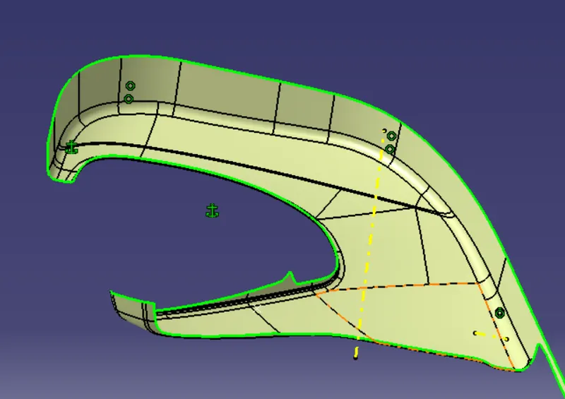
3.3.Creation of C Surface -
The edges of the Class-A surface are extracted using the multiple extracts and surface that are parallel to the main tooling axis are made with sweep draft angle 3 degree and surfaces that are perpendicular to the main tooling axis are made with sweep reference surface. At last join the all surfaces.
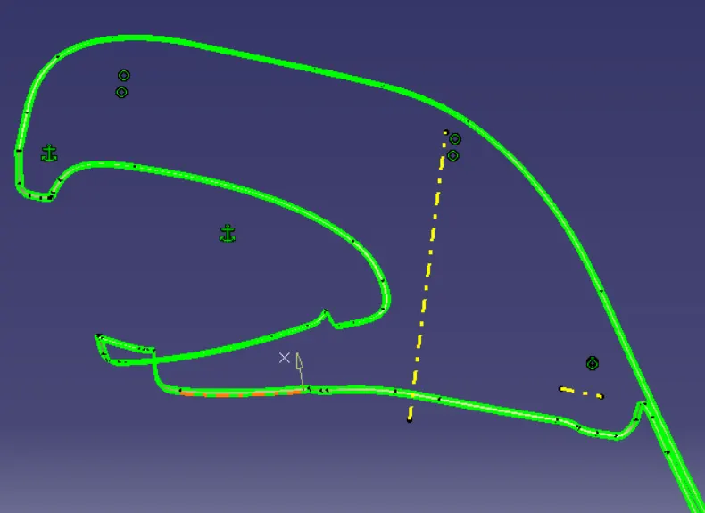
3.4.Final Trims -
Joining the Surface A + Surface B + Surface C and last close surface.
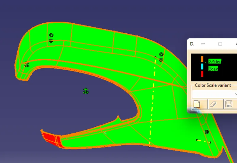
3.5.DESIGN OF HEAT STAKES WITH RIBS :
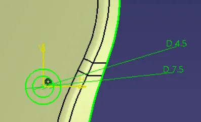
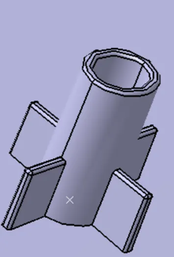
We took a geometrical set and drawn a sketch with reference of master section and projection point, after given PAD to the sketch with in the dimension limits as, with NEUTRAL FIBER.
Thickness of the walls is 1mm , Height of heat stake - 25mm , Height of suppoting rib – 3-6mm ,
Draft of 0.5 degree and fillet of 0.25mm.
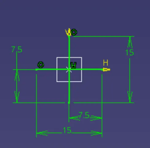
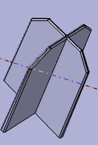
3.6 DESIGN OF 4 WAY LOCATORS :
We took a geometrical set and drawn a sketch with reference of plane and projection point, after PAD the sketch with in the dimension limits as, with NEUTRAL FIBER.
THICKNESS = 1mm and HEIGHT-28mm
Given a DRAFT = 0.2 (As tip is making less than 0.75mm so draft given 0.2) Entry chamfer - 3mm at 45 degree and given a fillet - 0.25mm
With paste special and translation created another 4way locator. Assemble and union trim with main body.
3.7.Dog House design -
Dog house is an engineering feature used in the plastic trim design. Dog houses are used as supporting features. Sometimes other engineering features like snaps; locators, etc. are mounded on them to increase their strength. Dog house and other engineering Features are built on B-surface.
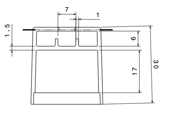
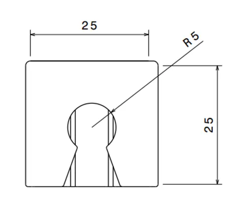
With help of above design rules and master section created dog house following OEM standards
3.8.Push Pins- Push pins are used for joining one component to another . These are basically attached to the doghouse. For creating the push pins the following reference was taken for dimensions.
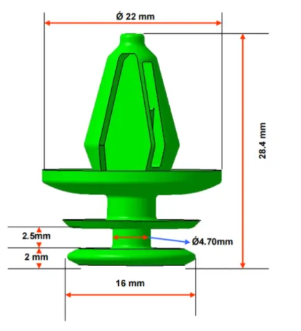
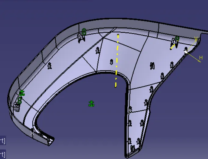
Fig.Lower Substrate with Engineering Features
4.Bottle Holder -
4.1.Tooling Axis - Generally 3 methods used to create the tooling axis.
- Normal to plane (Large surface avilable).
- Bisecting the line.
- Point and Direction.
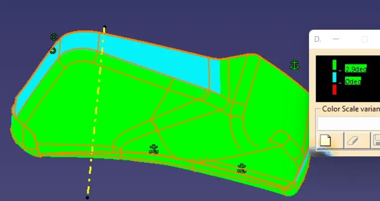
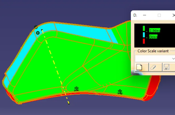
For A Bottle Holder Point and Direction is used to create main tooling axis and Class A surface clears in draft analysis.
4.2.Class B Surface -
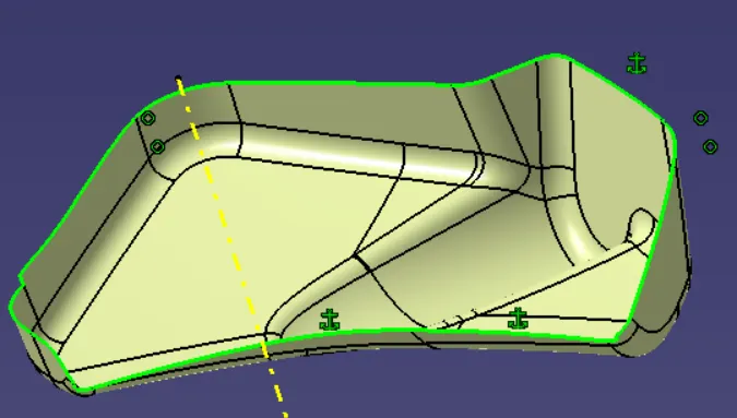
To create the class B surface, offset the class A surface inside as per our thickness requirement (here the master section given and thickness is 2.5mm, so offsetted the class A to 2.5 mm inside). Once the offset is created, we can observe some patches on the offset surface by taking the boundary for the offset surface, those patches are formed due to the fillets on the class A surface. We need to cover those patches with the help of the multi-section surfaces command by extracting the patch boundaries. Once all the patches on the offset are covered properly join all the patches with the offset surface, to get the replicated surface of the class A surface.
4.3.Creation of C Surface -
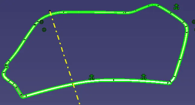
The edges of the Class-A surface are extracted using the multiple extracts and surface that are parallel to the main tooling axis are made with sweep draft angle 3 degree and surfaces that are perpendicular to the main tooling axis are made with sweep reference surface. At last join the all surfaces.
4.4.Final Trims -
Joining the Surface A + Surface B + Surface C And last close surface.
4.5.Flanges-
Flanges are the joining features that help to assemble different components. The mastersection was used to make flanges. After creating one flange axis to axis sytem was used to translate the flanges. The draft of 0.5 is given to the flanges. The gap between flanges should be 60-100 mm. Boolean operations were used to add attachment features into closed body.
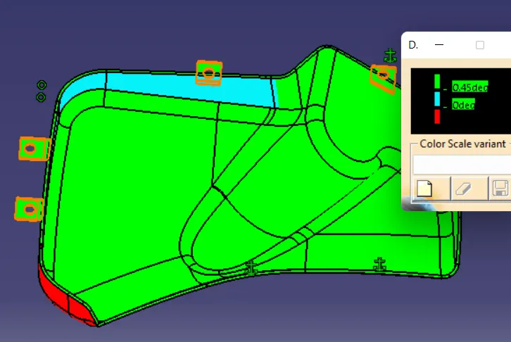
Fig.Bottle Holder with Flanges
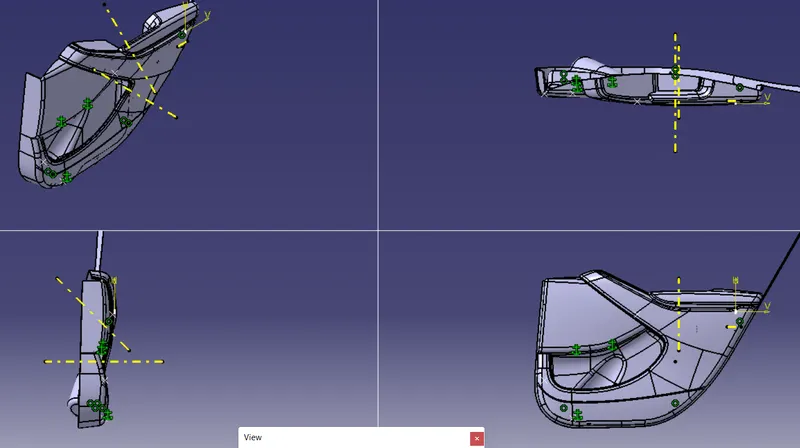
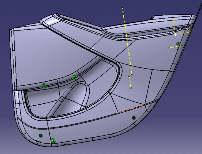
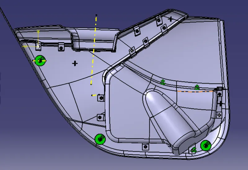
Final Door Trim Engineering Features Different View
Conclusion
Door Trim was made with OEM guidelines using Part Workbench and Generative Shape Design Workbench using CATIA V5.