Week 11 - Final project
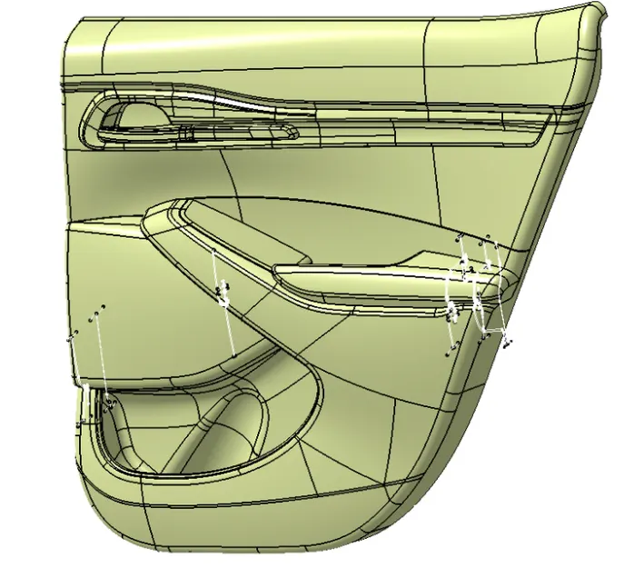
AIM: To create a CAD model from the Class-A surface given as input of a Door Panel.
SOFTWARE USED: CATIA-V5.
INPUT: Master section line and Class A surface.
INTRODUCTION:
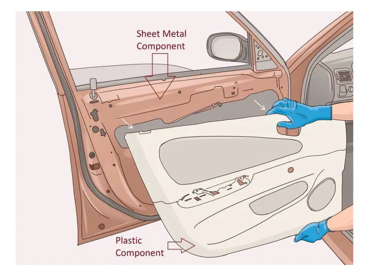
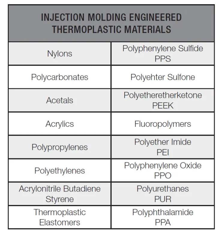
Door panel is a part of the vehicle having a plastic component , wire harness inside and sheet metal components. They are expected to meet a variety of design specifications regarding safety, aesthetics, and functionality. Different types of material are used for plastic components as per requirement.
Class-A Surface:
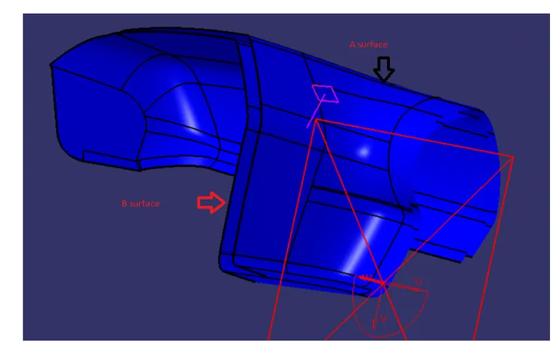
A surface basically, which is seen by the consumer. A surface must be defect free and aesthetically good. This is only possible with high-class finish and good forms. This is the reason why in design industries Class-A surfaces are given more importance. Although, strictly, it is nothing more than saying the surfaces have curvature and tangency alignment. Class A surfacing is done using computer-aided industrial design applications named as Autodesk Alias Surface. Industrial designers develop their design styling through the A-Surface.
Class-B surface:
Class B surfaces are offset from A surface. You can see inside of your car glove box, ash tray, etc. These are not seen by the customer generally.
Class-C surface:
C surfaces are made with the help of A and B surfaces. C surfaces are nearly equal to the thickness of the part. Flashes always come on the either edge of the C surface.
Injection Molding Materials:
B-Side Features:
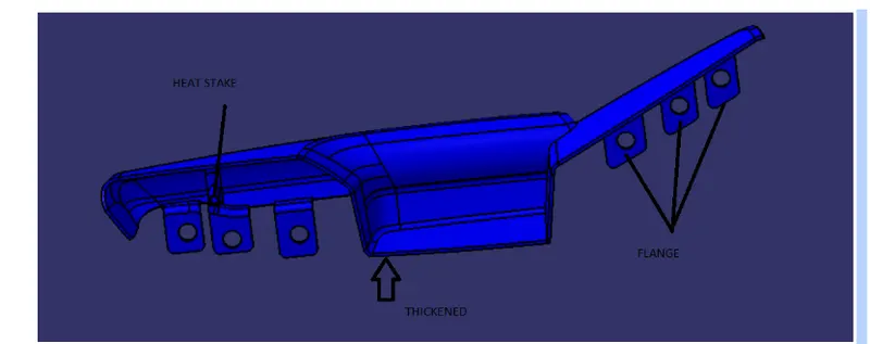
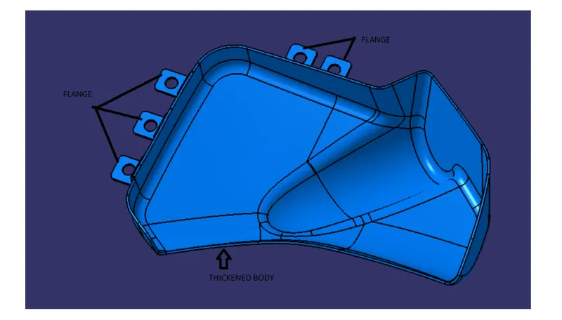
B side features are Dog house, rib, rib boss, 2 way locator, flange and 4 way locator.
RIB:-
Rib is a thin solid part which is used to give strength to the part . Rib is made with parameters given below:-
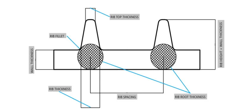
1)Rib Thickness:
Bottom Rib Thickness :( 0.3 to 0.6) * Wall Thickness
Note: Top Rib Thickness should be minimum of 0.75mm.
2)Rib height:
Rib Height= 5 * Wall Thickness.
3)Rib fillet:
Rib fillet = 0.125 * Wall Thickness.
4)Wall Thickness:
Wall thickness should not be less than 5 mm.
2 WAY LOCATOR:-
2-way locators are used to fix the movement of parts with a degree of freedom.
4-Way Locators:
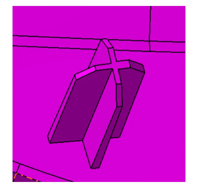
These are the locators which arrest the 4 degrees of freedom by four ribs junctioning together.
Heat Staking:
Heat stake :-
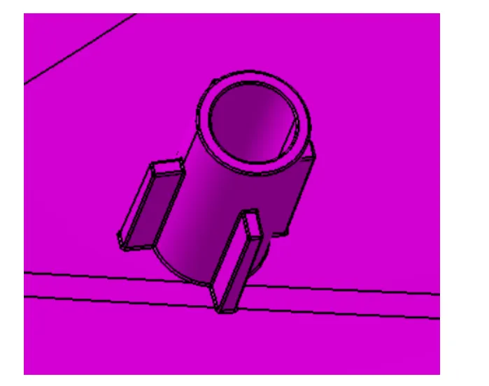
Heat stake is made for joining two parts for plastic parts .The process is to deform the plastic material using heat and force at a set process time.
Draft Analysis:
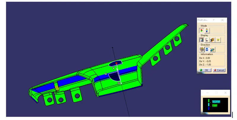
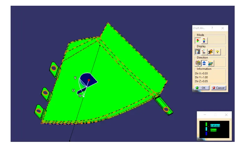
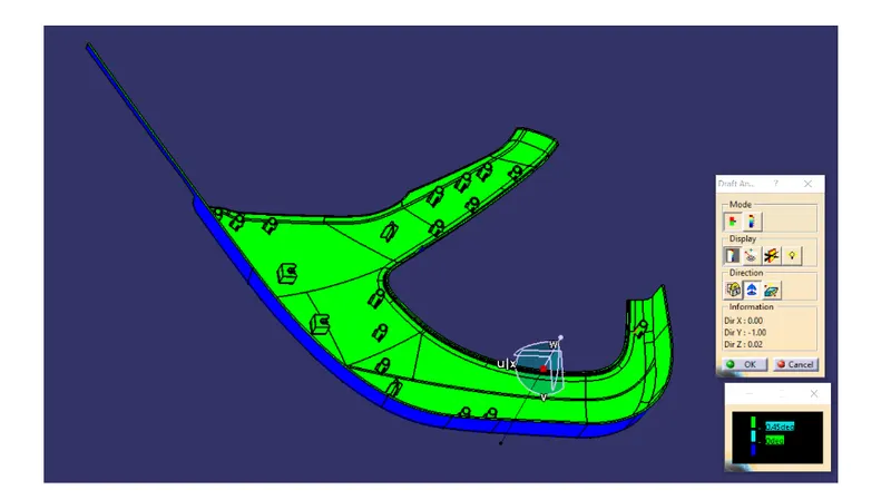
Draft analysis is very important for manufacturing. If the draft is not cleared , then this part is not possible to manufacture by core cavity process. Every heat stake is drafted 0.5° per side. Not even heat stake but also ribs, 4 way locator.
Every part must clear its draft analysis.
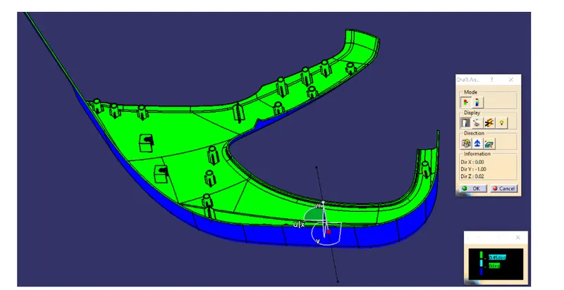
The maximal draft analysis accuracy is 0-3 deg.
Sequence of Operations to generate CAD Model of a plastic component:
- Extracting the input Class-A surface into different parts of Assembly.
- Looking for defects in Class-A surfaces.
- Improving Class-A surface by patching defects.
- Improving Class-A surface as per Master section.
- Creating Tooling Axis.
- Creating Class-B surface.
- Creating Class-C surface.
- Creating a Closed Body.
- Creating a Dog House.
- Creating Locator as per Master Section.
- Creating Ribs as per requirement.
- Draft Analysis.
- Adding Draft as per requirement.
- Creating Side core Tooling Axis.
DESIGNING OF PLASTIC COMPONENT FOR GIVEN DOOR TRIM PANEL CLASS-A SURFACE:
Door Trim Panel consists of following Components.:
- Door Arm-Rest.
- Upper Map Pocket.
- Lower Map Pocket.
- Lower Substrate.
- Upper Substrate.
- Flanges.
- Heat stakes and Dog Houses.
Extracted Surfaces: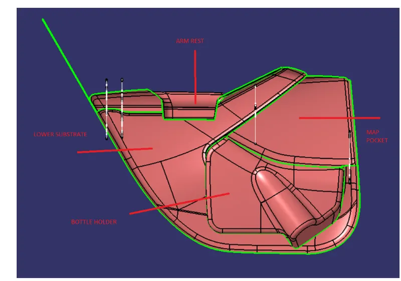
1.Door Arm Rest:
In the front of the car, a central armrest, which commonly folds away based on user preference, will also often include a storage compartment and sometimes even cup holders.
Extracted Class-A Surface:
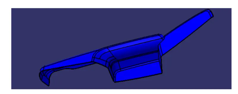
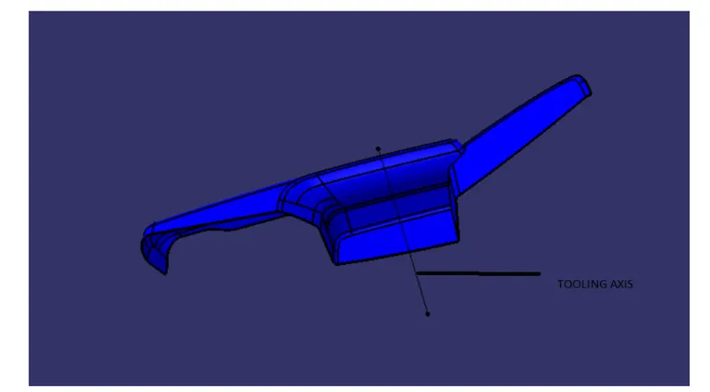
Creation of Tooling Axis for Arm-Rest :
 Creation of thickened plastic component with B-Side Features:
 Draft Analysis of Arm Rest:
2.Map Pocket:
An aperture in the door trim panel defines the opening into the map pocket. The front portion defines a lower front wall and a pair of side walls. The region above the lower front wall is generally open to provide access to the storage compartment of the map pocket. The map pocket assembly is then attached to the rear surface of the door trim panel such that the opening of the map pocket is generally aligned with an opening formed in the door trim panel.
Extracted Upper Map Pocket Class-A surface:
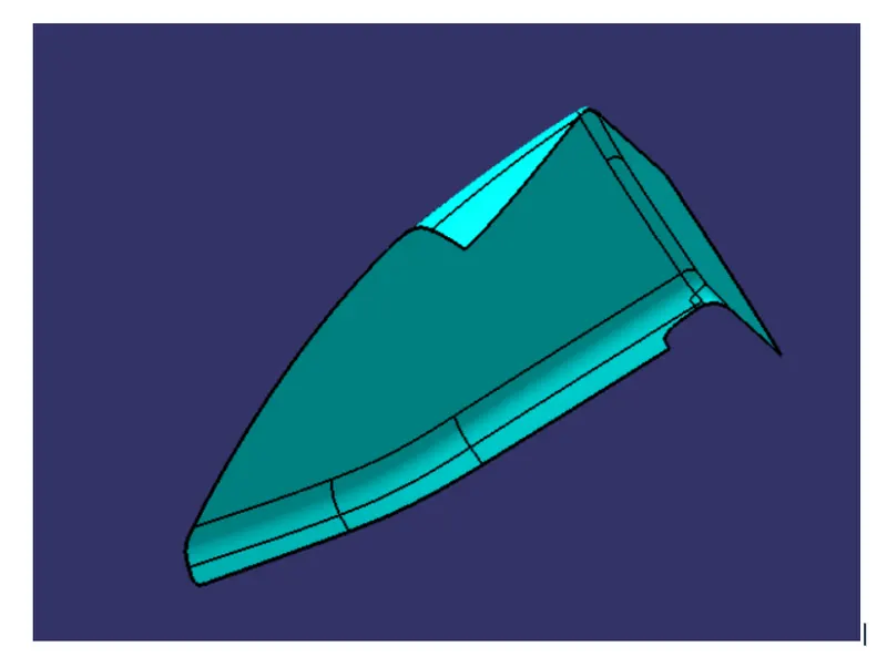
Creation of Tooling Axis for Upper Map Pocket:
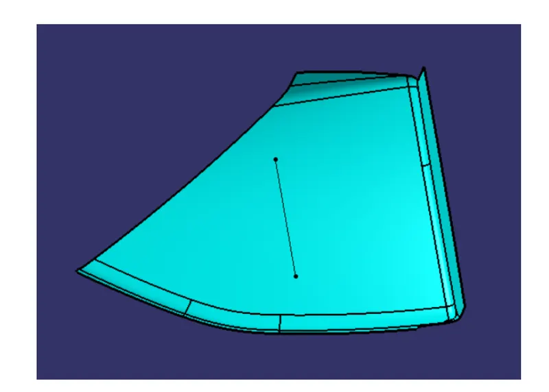
Creation of thickened plastic component with B-Side Features:
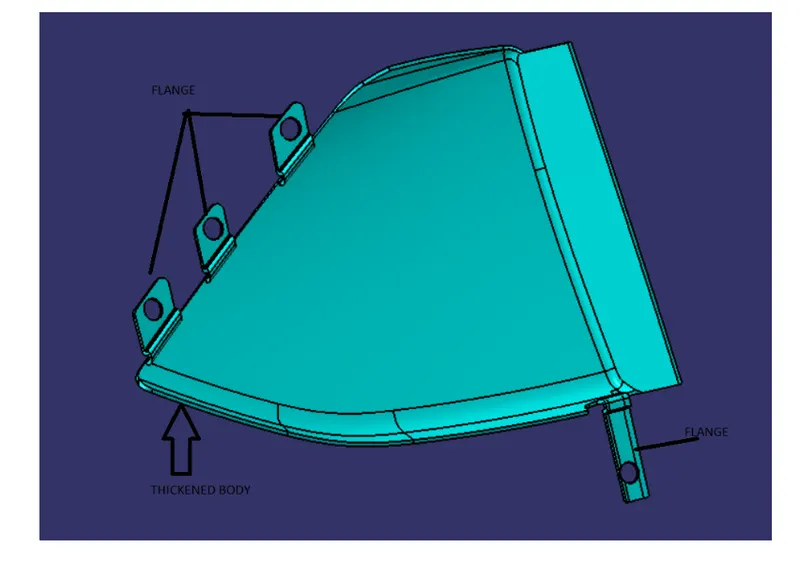
Draft Analysis of Upper Map Pocket:
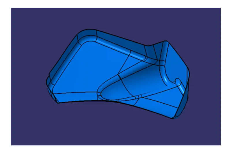
Extracted BOTTLE HOLDER Class-A Surface:
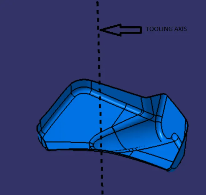
Creation of Tooling Axis for BOTTLE HOLDER :
Creation of Thickened plastic component with B-Side Features:
 Draft Analysis of BOTTLE HOLDER :
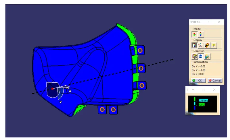
Extracted Lower Substrate Class-A surface:
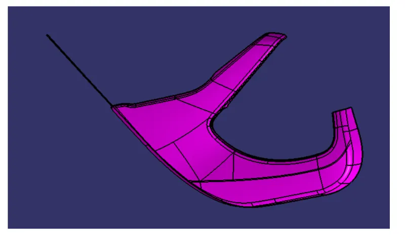
Creation of Tooling Axis for Lower Substrate:
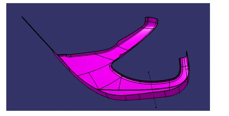
Creation of Thickened Plastic component with B-Side Features:
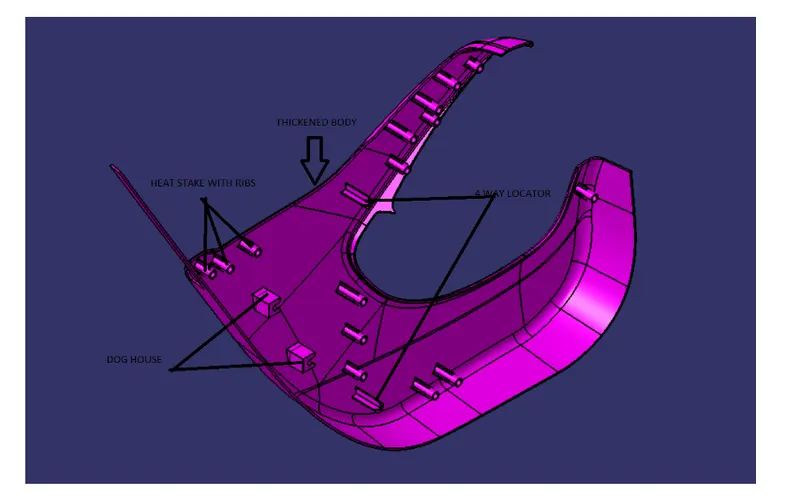
Draft Analysis of Lower Substrate:
CONCLUSION:
Hence, Input surface is extracted into different components and B-side Features are created considering the OEM standards to design Plastic components.