Week 11 - Final project
AIM:
Creation of Door Panel considering following inputs as like in OEM and tier1 companies
- Class A surface
- Nominal thickness: Refer to master sections
- Attachment strategy
OBJECTIVES:
- Create 4 components of door panel: lower substrate, map pocket, hand rest and push pin.
- Create thickened part using master section for reference
- Create the mounting features as per design guidelines in the industry and with master sections
- Draft analysis & Tooling analysis
- Creation of parting lines and check tooling feasibility
THEORY:
DESIGN LIFE CYCLE:
- Concept Sketch: These sketches are freehand drawings made by designers as a simple way to explore initial ideas for designing.
- Class A creation: Class A styling is done using CAD software mainly Alias. In this stage we create aesthetic surfaces which are visible surfaces in exterior and interior. Class A surfacing complements the prototype modelling stage by reducing time and increasing control over design iterations.
- Clay Modelling: With the help of Clay modelers a prototype will be built. This gives the designers a realistic representation of surfaces and how the vehicle will look. Both exterior and interior parts and modeled in clay.
- NPD CAD: Using CAD software the product is made for manufacturing purposes considering the design rules and manufacturing process. After NPD CAD the product is manufactured.
GUIDELINES FOR B-SIDE FEATURES (RIBS, DOG-HOUSE)
RIBS:
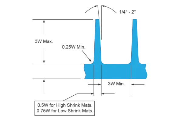
- Draft - min of 0.3deg.
- Thickness - 0.5 times the primary thickness which is 2.5mm here.
- Height – 3 to 5 times the primary thickness.
- Spacing – Min of 3 times the primary thickness between two ribs.
- Thickness at top should be min of 0.75mm.
DOG HOUSE:
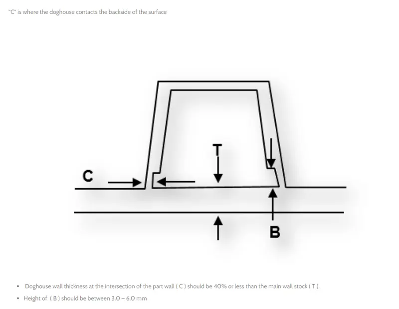
- C should be less than 40% of wall thickness.
- B should be between 3-6mm.
- Min height of the dog house is 6mm. Less than 6mm cause weak steel condition.
- Min width should be 12mm.
- Draft is 0.3deg.
PROCEDURE:
CLASS A SURFACE PROVIDED BY THE OEM:
In this project the Class A surface is provided from the Aesthetic design team to the NPD CAD team. The team will inspect the manufacturability of the model and check if it is following the design principles. If the team finds the model okay they proceed with extracting the surfaces part by part and work on class A, B and C surfaces. Then the engineering team will provide the mounting features also. Shown below is the Class A surface that I got to work on.
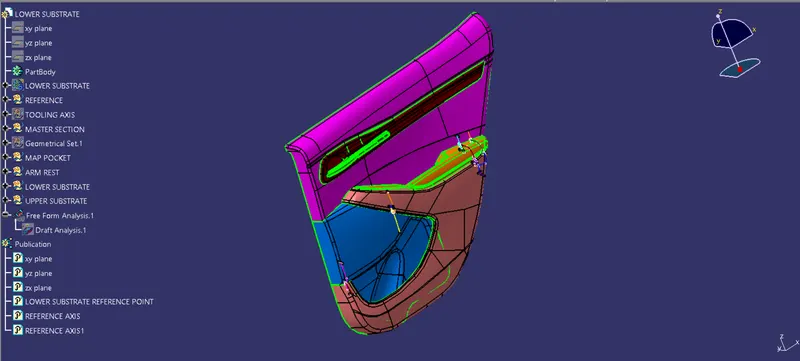
FIG: Class A surface for Door Panel
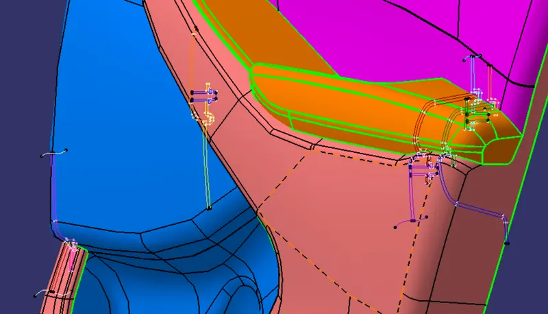
FIG: Master Section available for the model
Master Section: It is used for a feasibility checks. To check the clearance with mechanism and the fixation strategy will be decided in the master section.
Divided the model into 4 part files:
- Map Pocket
- Arm rest upper
- Arm rest lower
- Lower substrate
MAP POCKET:
Step 1: EXTRACTING CLASS A
Extracted the required surfaces from the main input and joined them together as one part. This become my class A surface.
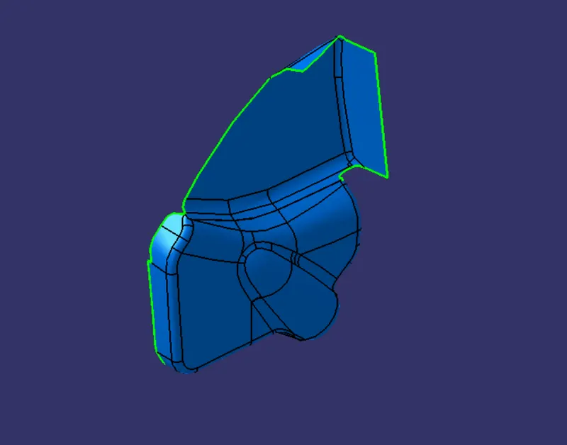
FIG: Map Pocket Class A surface
Step 2: CREATING TOOLING AXIS:
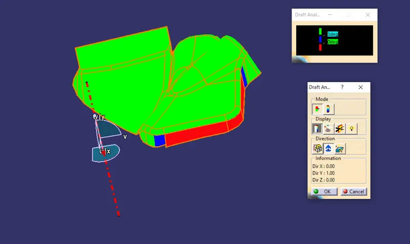
FIG: Main tooling axis with draft analysis
When I performed draft analysis I found out issues with the A surface which is shown in fig. This issue can be rectified by the permission of the aesthetic team.
After performing draft analysis then created the flanges for the class A surface. The Master section was used as a reference for creating the flanges.
STEP 3: CLASS B SURFACE
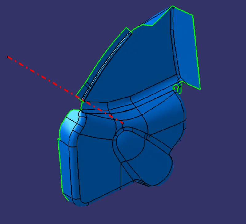
FIG: Class B surface with flanges
Class B surface was created by offsetting class A surface to 2.5mm. Proper fillets are provided.
STEP 4: CLASS C SURFACE
Class C surface was created by sweeping the boundary of class A surface along the tooling axis with a min of 3deg outwards. In some areas 90deg sweep was given which are perpendicular to the tooling axis.
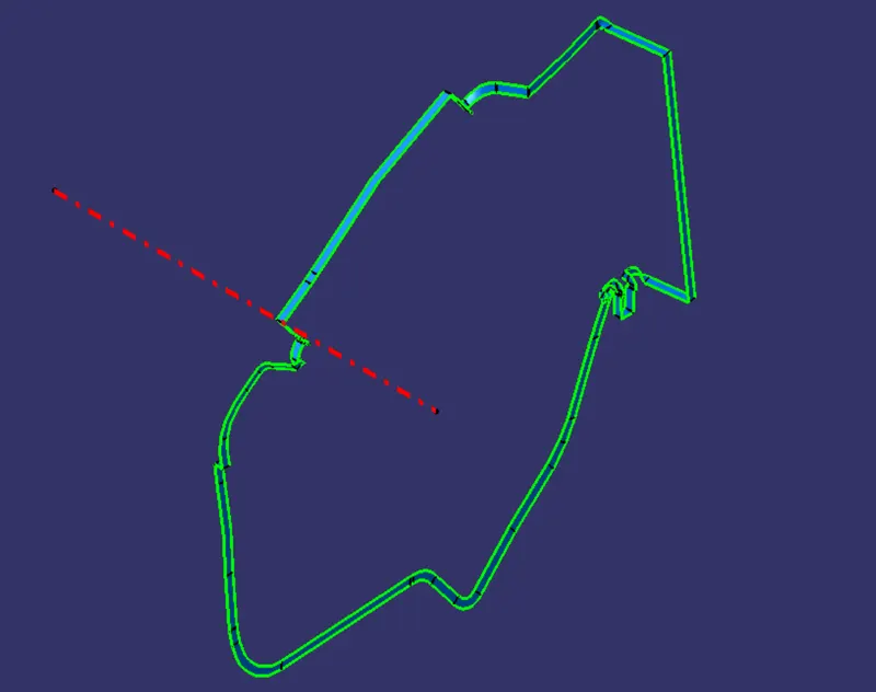
FIG: Class C surface
STEP 5: WHOLE MAP POCKET BODY
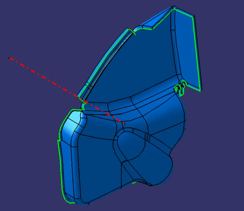
FIG: Joined class A with C surface
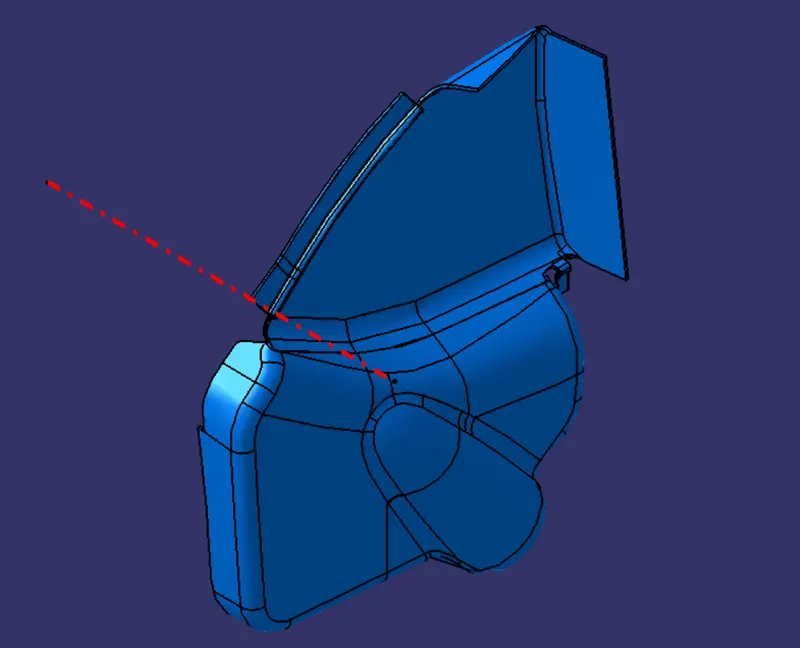
FIG: Final closed body
Here the joined surface was trimmed with Class B surface in order to form the closed body.
STEP 6: CREATING HOLES ON THE FLANGES FOR HEAT STAKE
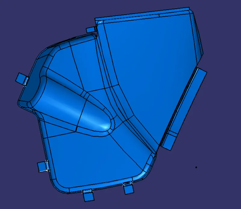
FIG: Created flanges for the closed body
STEP 7: CREATING THE SOLID BODY USING BOOLEAN OPERATIONS AND ADDING NECESSARY FILLETS TO THE BODY.
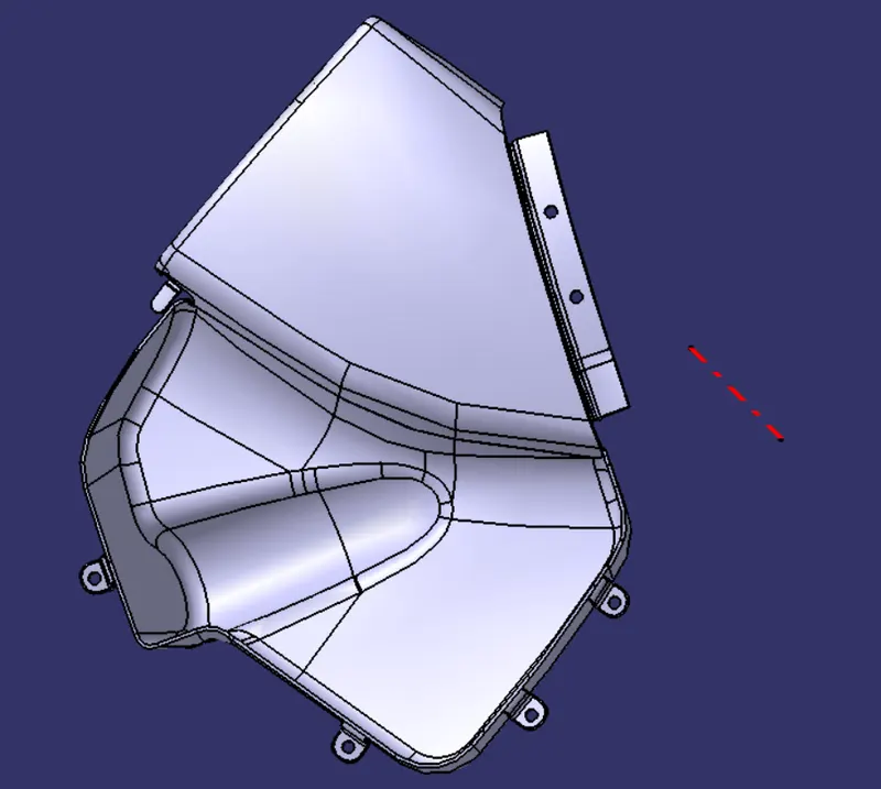
STEP 8: DRAFTIING
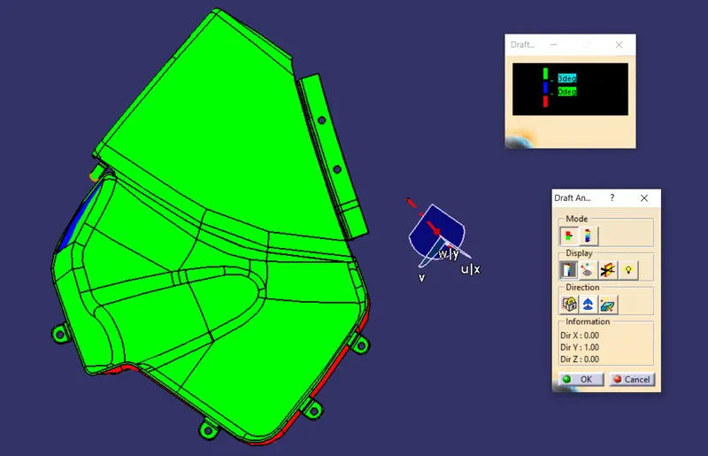
FIG: Draft analysis report of Map Pocket
ARM REST UPPER:
STEP 1: EXTRACTING THE REQUIRED SURFACES FROM THE INPUT
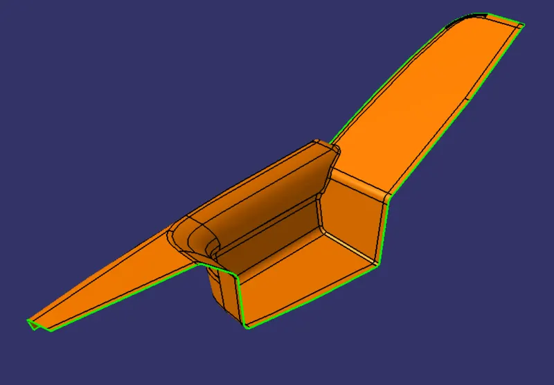
FIG: Arm Rest Upper Class A surface
Step 2: CREATING TOOLING AXIS
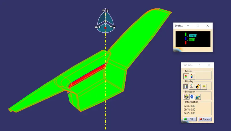
FIG: Main tooling axis with draft analysis
After performing draft analysis I found there is an undercut portion. So decided to give a slider.
When I gave the slider I was able to clear the red area from the previous fig.
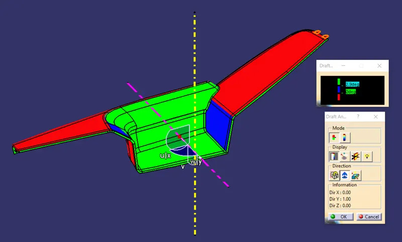
FIG: Slider tooling axis with draft analysis
STEP 3: CLASS B SURFACE
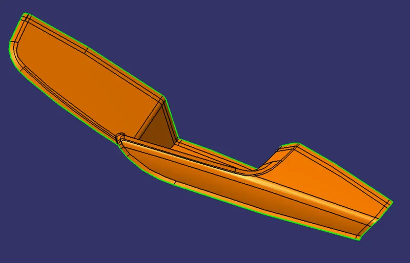
FIG: Class B surface
Created Class B surface by offsetting the Class A for 2.5mm. Proper fillets were given according to the master section.
STEP 4: CLASS C SURFACE
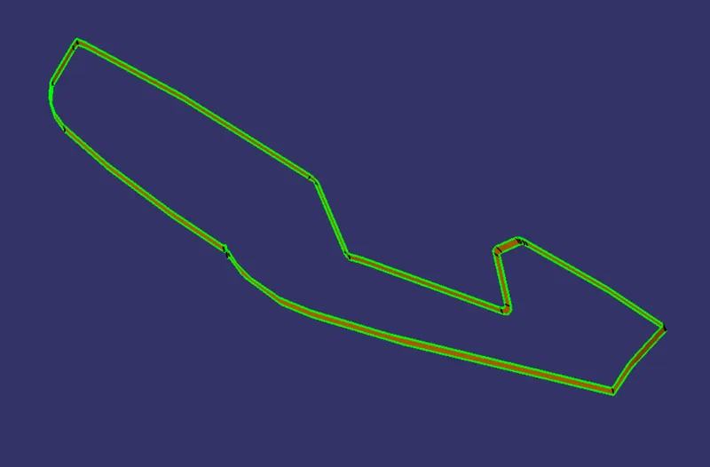
FIG: Class C surface
Class C surface was created by sweeping the boundary of class A surface along tooling axis with min of 3deg outwards.
STEP 5: CREATED THE CLOSED BODY
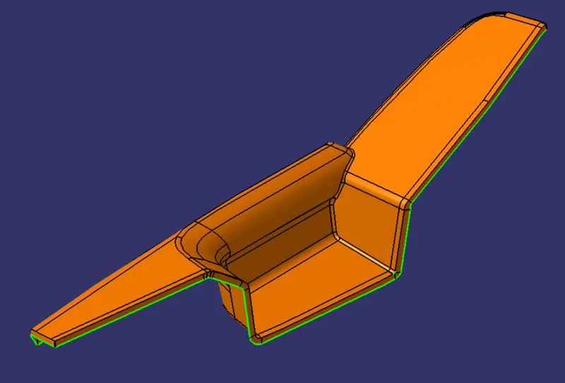
FIG: Joined Class A and C surfaces
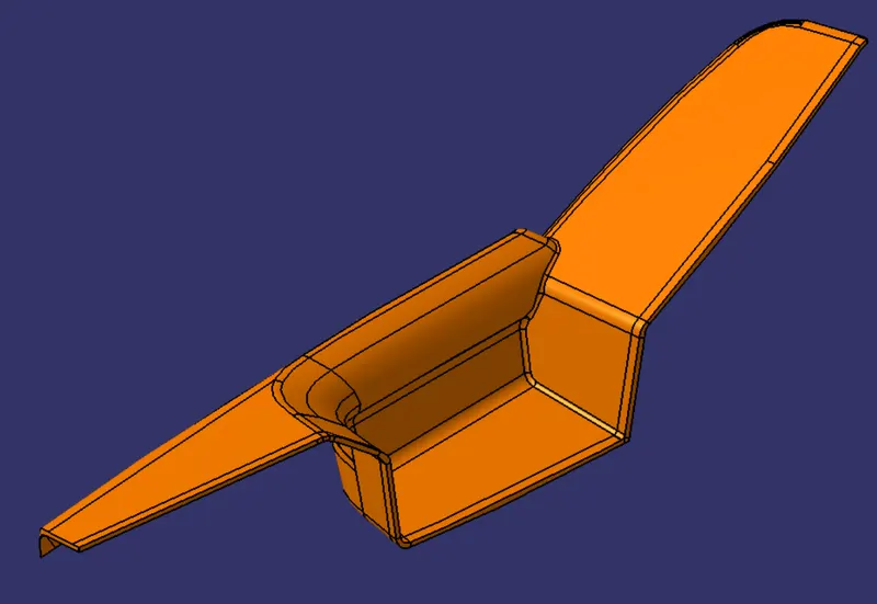
FIG: Closed body
Here the joined Class A and C surface is trimmed with Class B surface to get closed body.
STEP 6: CREATED MOUNTING FIXTURES
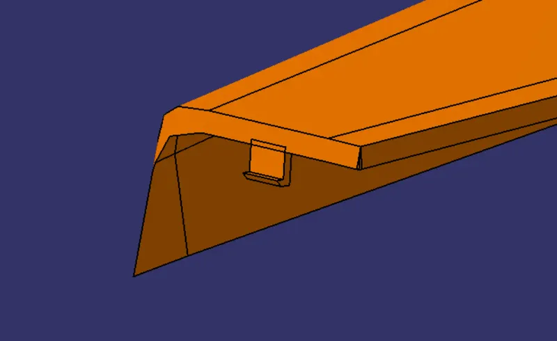
FIG: L clip for easy removal and installation
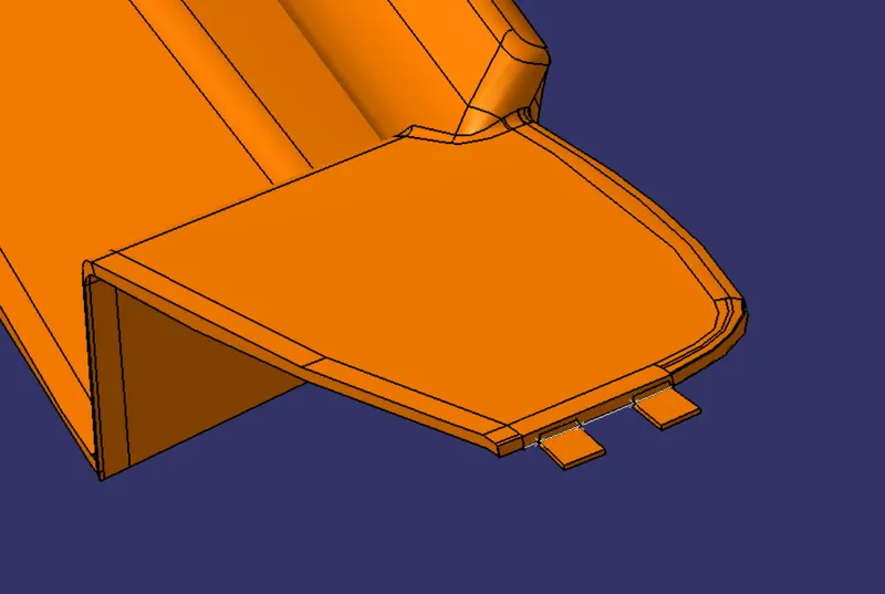
FIG: Two legs for locating the position
STEP 7: CREATING THE PART BODY USING BOOLEAN OPERATIONS AND ADDING NECESSARY FILLETS TO THE BODY
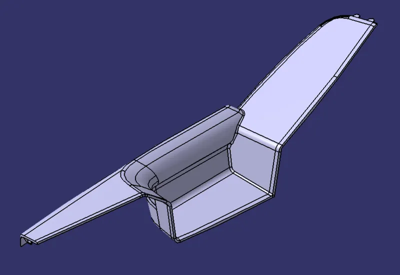
STEP 8: DRAFTING
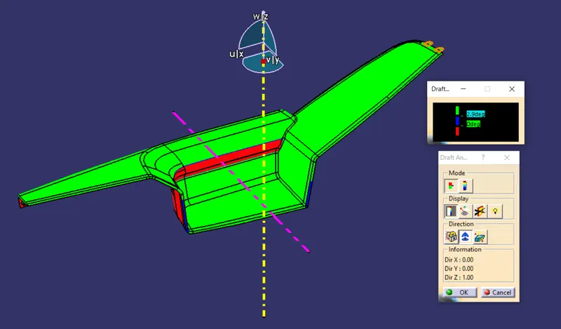
FIG: DRAFT WITH RESPECT TO MAIN TOOLING AXIS
FIG: DRAFT WITH RESPECT TO SLIDER AXIS
ARM REST LOWER:
STEP 1: EXTRACTING THE REQUIRED SURFACES FROM THE INPUT
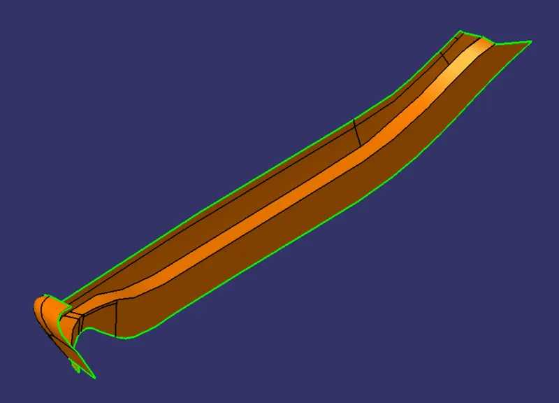
FIG: Class A surface of Lower Arm Rest
Step 2: CREATING TOOLING AXIS
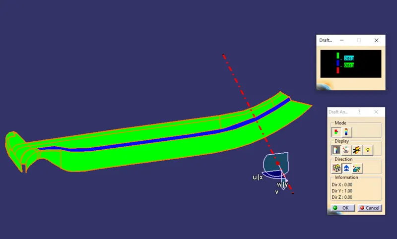
FIG: Main tooling axis with draft analysis report
Extracted surfaces from the input was joined together to form Class A surface. After that I performed draft analysis.
STEP 3: CREATE CLASS B SURFACE
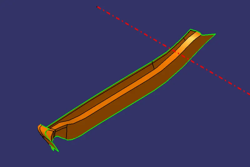
FIG: Class B surface
Created Class B surface by offsetting the Class A for 2.5mm. Proper fillets were given according to the master section.
STEP 4: CLASS C SURFACE
Class C surface was created by sweeping the boundary of class A surface along tooling axis with min of 3deg outwards. In some areas 90deg sweep was given which are perpendicular to the tooling axis.
STEP 5: CREATED THE CLOSED BODY
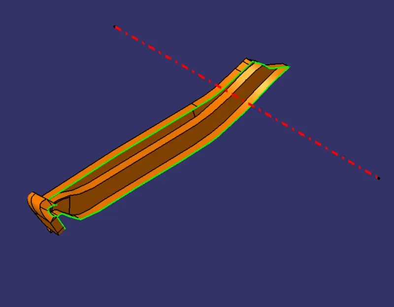
FIG: Joined Class A with C surface
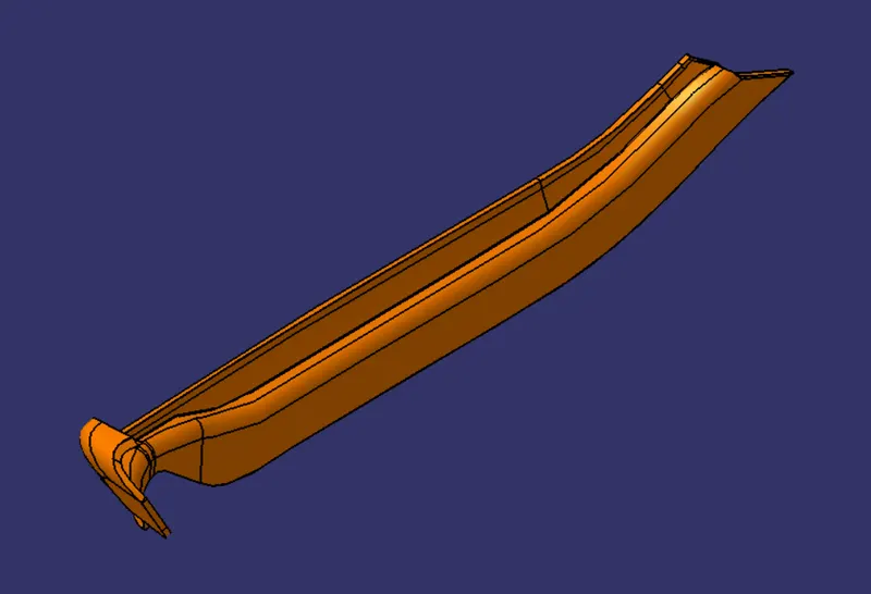
FIG: Closed body
Here the joined Class A and C surface is trimmed with Class B surface to get closed body.
STEP 6: CREATED HEAT STAKE HOLE FOR MOUNTING
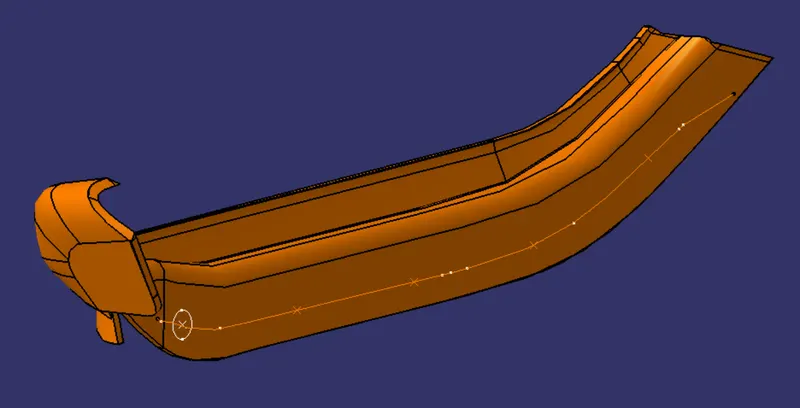
FIG: Projected the heat stake sketch to the arm rest model
STEP 7: CREATED THE PART BODY
Here the closed body was converted to the part body. Then the projected circle was padded in part workbench and with Boolean operator removed the pad from the main body to create the hole.
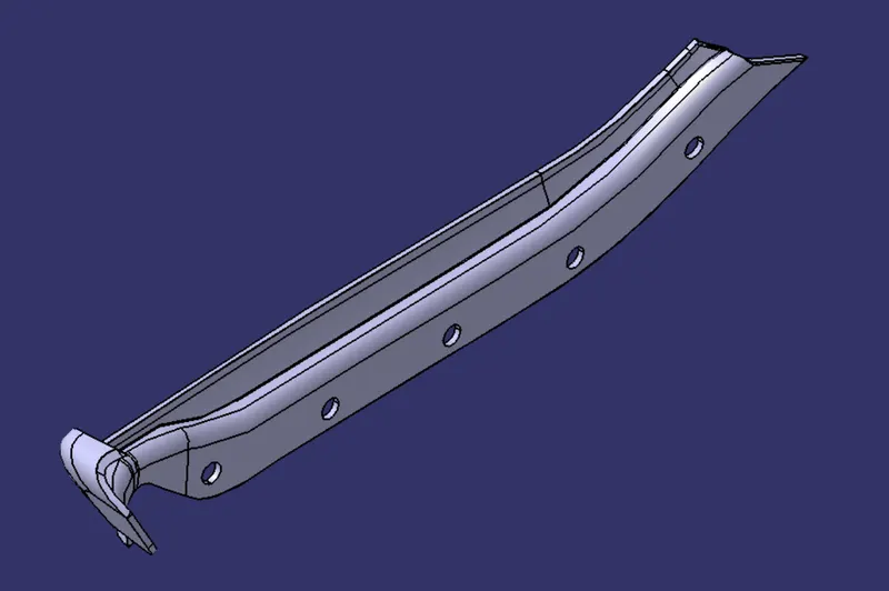
FIG: Arm rest lower
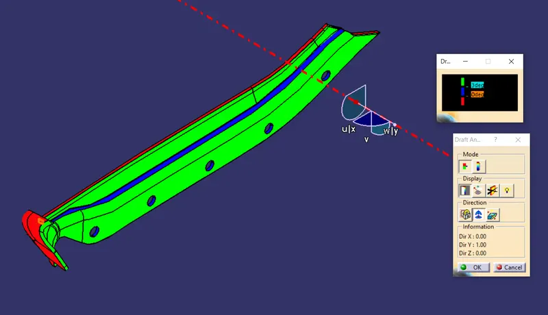
STEP 8: DRAFT ANALYSIS
LOWER SUBSTRATE:
STEP 1: EXTRACTING THE REQUIRED SURFACES FROM THE INPUT
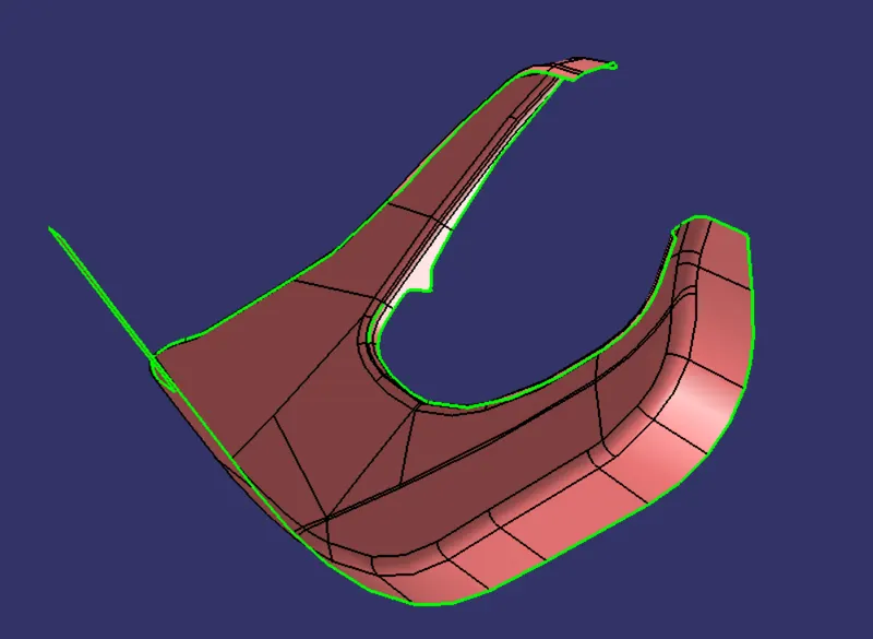
FIG: Class A surface of Lower Substrate
STEP 2: CREATED TOOLING AXIS
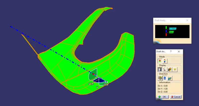
FIG: Main tooling axis with draft analysis report
Here I extracted surfaces from the input model and joined together to get Class A surface. After that I performed draft analysis. The draft analysis report is given above.
STEP 3: CREATE CLASS B SURFACE
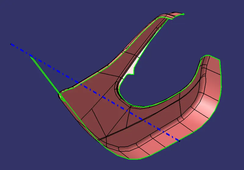
FIG: Class B surface
Created Class B surface by offsetting the Class A for 2.5mm. Also created flanges according to the master section given. Also given the proper fillets.
STEP 4: CLASS C SURFACE
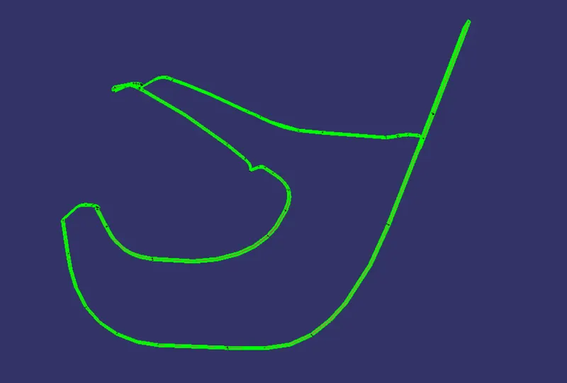
FIG: Class C surface
Here the Class C surface was created by sweeping the boundary of class A surface along tooling axis with min of 3deg outwards. In some areas 90deg sweep was given which are perpendicular to the tooling axis.
STEP 5: CREATED THE CLOSED BODY
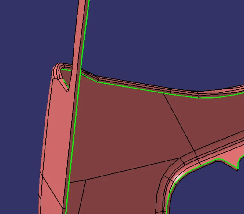
FIG: Class A with Class C
Here I joined the class A surface with class C surface and trimmed them with the class B surface to get the closed body.
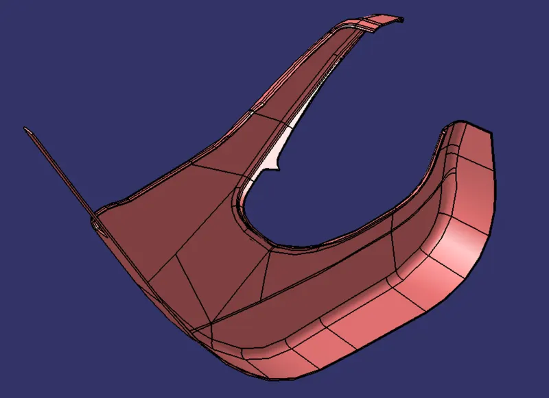
FIG: Closed body
STEP 6: CREATED THE PART BODY
Using close surface tool created the solid body.
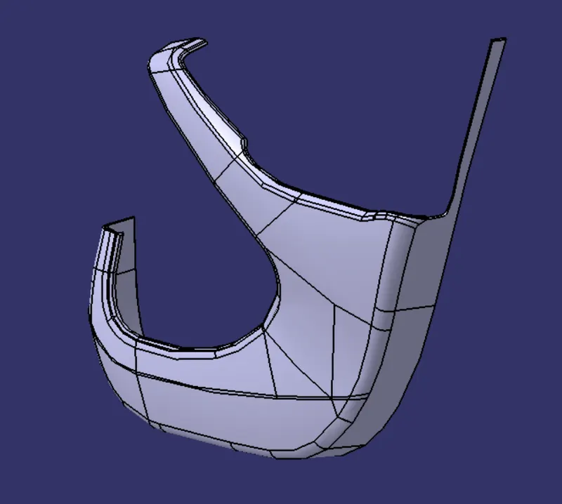
FIG: Lower substrate closed body
STEP 7: CREATE B SIDE FEATURES
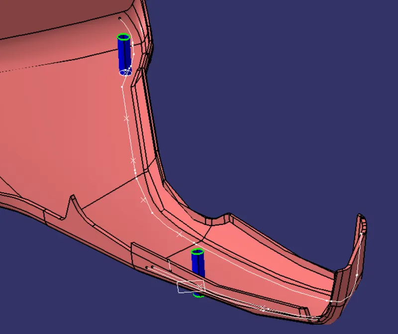
FIG: Heat stake and flanges
After creating the heat stake surface, it was thickened to form solid in part workbench then translated to the required positions.
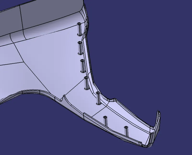
FIG: Heat stake translated to required positions
After that created the Dog house with the proper design rules.
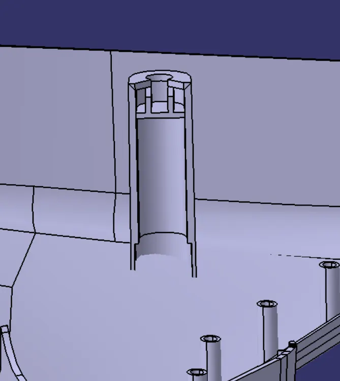
FIG: Dog House
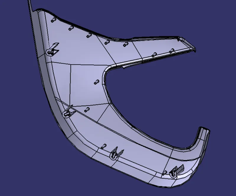
FIG: Translate the dog house to the required positions
Proper drafting was given to the heat stake and dog house. Also gave the proper fillets.
STEP 8: DRAFT ANALYSIS
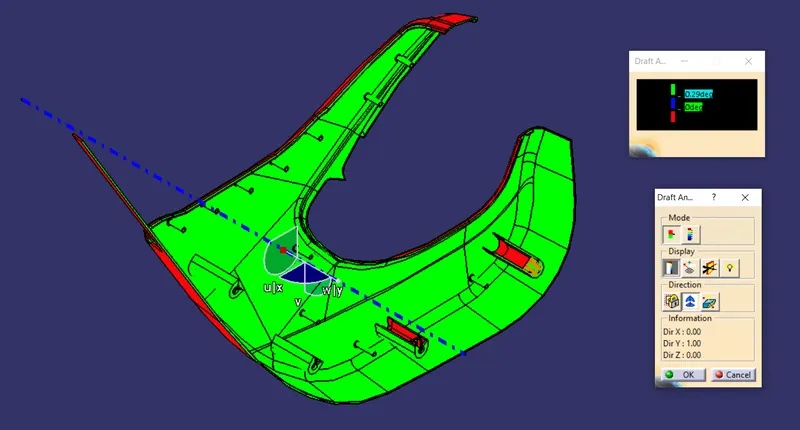
FIG: Draft analysis report with main tooling axis
In the main tooling axis I was not able to clear the inside of dog house. So I created the lifter axis for each dog house.
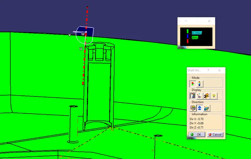
FIG: Lifter axis with draft analysis
PUSH CLIP:
STEP 1: CREATE THE SKETCH FOR PUSH PIN
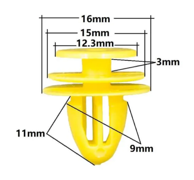
FIG: General dimension of push clip
After creating the sketch according the general dimension. Using sketch based feature tool. Developed the sketches into a solid body.
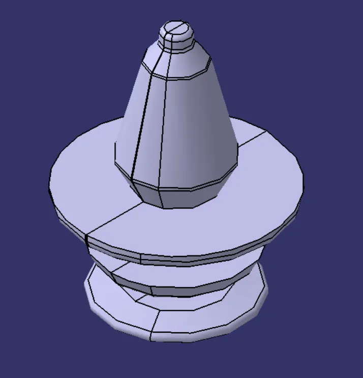
FIG: Push Clip
STEP 2: CREATE TOOLING AXIS
Created tooling axis normal to the ZX plane.
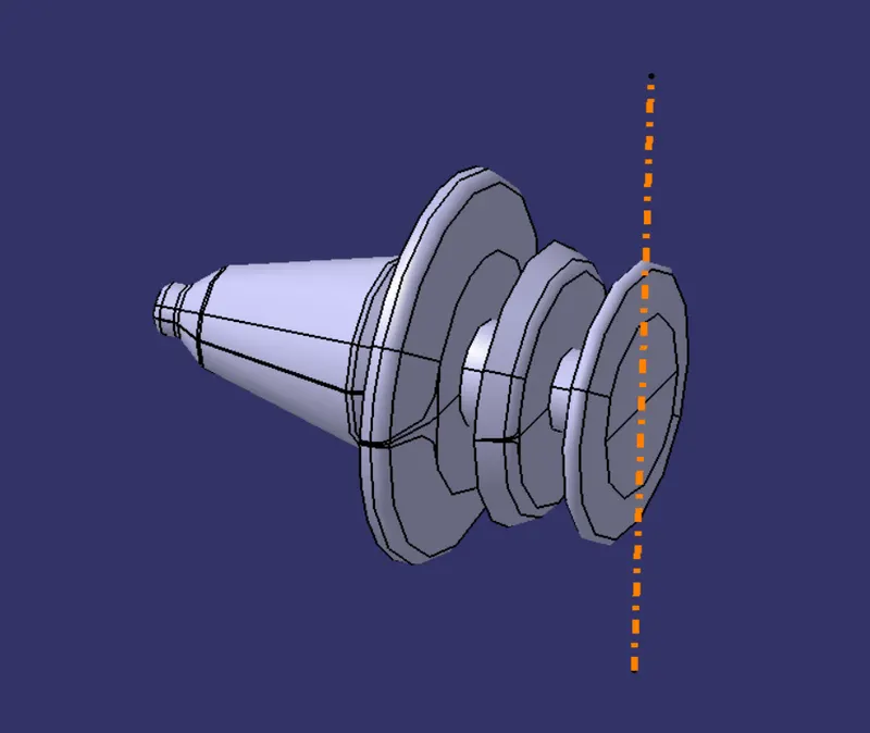
FIG: Tooling axis
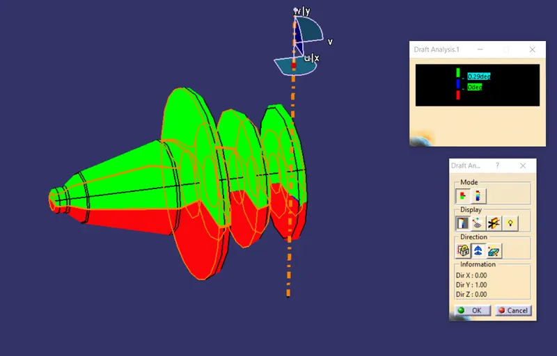
STEP 3: DRAFT ANALYSIS
FINAL PRODUCT:
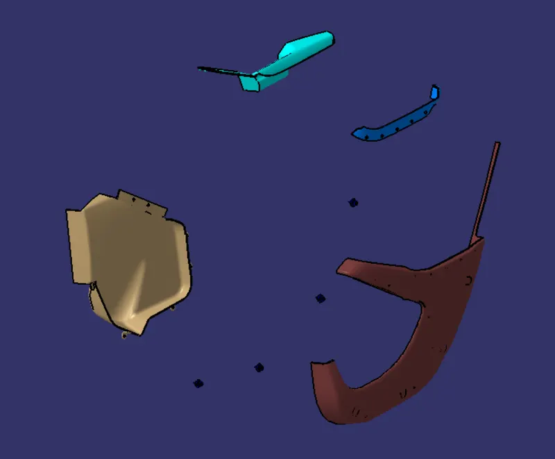
FIG: Exploded View
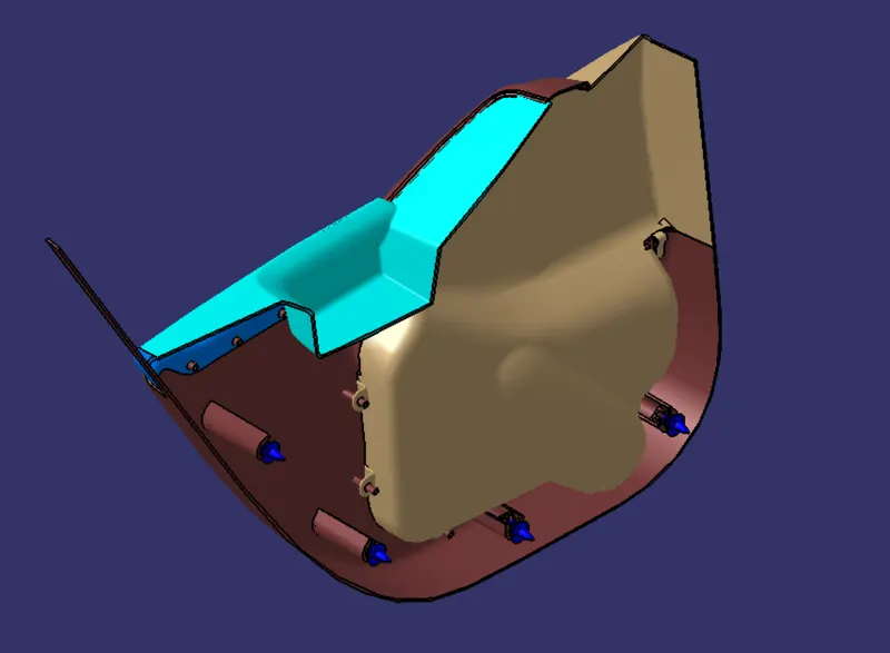
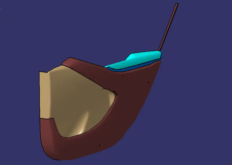
FIG: Assembled view