Control Logic for Washing Machine and Gear Shift
AIM:
- Implement control logic of a “Washing machine” using Stateflow.
- Make a Simulink chart for the “Gear shift”.
OBJECTIVE:
- Implement control logic of a “washing machine” using Stateflow as per given sequence:
- If the power supply is available, the system gets activated
- If the Water supply is not available, stop the process & indicate through LED
- Soaking time should be 200s followed by washing time of 100s.
- Then rinsing happens for next 20s & dryer runs for 50s
- After all the processes have completed turn on the finished LED
- Make a Simulink chart for the “Gear shift” logic as per below conditions:
|
Speed Range(kmph) |
Gear |
|
0 to 15 |
1 |
|
16 to 25 |
2 |
|
26 to 40 |
3 |
|
41 to 60 |
4 |
|
Above 61 |
5 |
Give speed input while the simulation is running & display the gear number.
THEORY:
Stateflow: It is a control logic tool used to model reactive systems via state machines and flow charts within a Simulink model. Chart block is used to represent stateflow in Simulink. It is generally used to specify the discrete controller in the model of a hybrid system where the continuous dynamics are specified using Simulink.
Control Logic: It is the decisions or conditions that controls the operations of the program. It takes command from user and acts own to perform the automated tasks. Control logic is modelled using control stateflow in matlab.
SIMULINK MODEL:
- Washing Machine
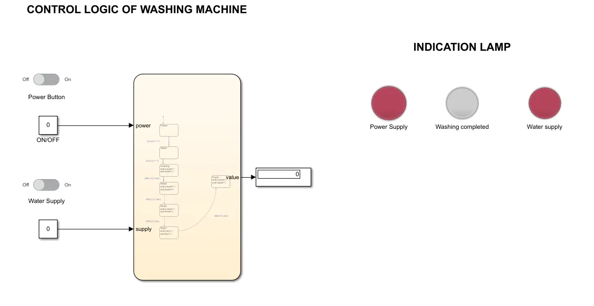
Fig: CONTROL LOGIC FOR WASHING MACHINE (Both power and water supply iin OFF state)
Explanation:
- Slider Switch: The slider switch block toggles the value of the connected block parameter between two values during simulation. Here the switch represents ON/OFF state of Power and water supply. For ON state it will give 1 and for OFF state it will give 0.
- Constant block: It is used to connect the slider switch to the input of chart.
- Chart block: It represents the stateflow of the washing process. Chart block has 2 input ports and 1 output port.
- Display block: It shows the output value.
- Lamp: Display the colour that reflects an input value.
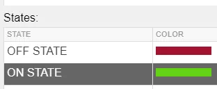
Explaining the stateflow:
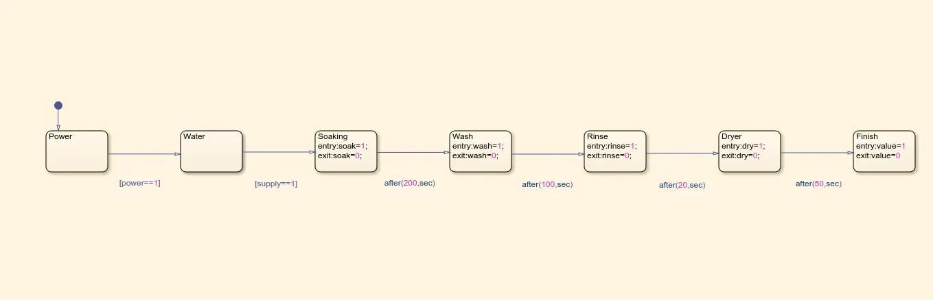
- Here 1st state check for the power supply if power == 1then only the transition happens to 2nd state else the process gets terminated.
- In 2nd state it checks for supply of water the transition happens only if the water supply in ON otherwise at that state the process terminates.
- In 3rd state soaking process is done for 200seconds. After 200seconds transition happens to 4th
- In 4th state washing process is done for 100seconds. After 100seconds transition happens to 5th
- In 5th state rinsing process is done for 20seconds. After 20seconds transition happens to 6th
- In 6th state drying process is done for 50seconds. After 50seconds transition happens to 7th
- In 7th state the entire washing process is completed and output is indicated as washing completed lamp.
2. Gear Shifting
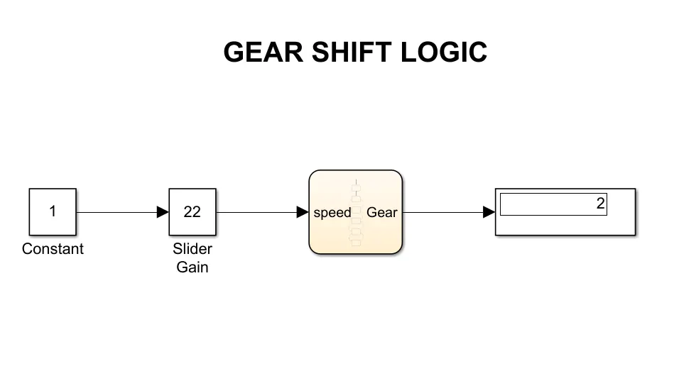
Here when the stimulation is running we have to vary the speed and according to the speed display the gear number.
Explanation:
- Slider Gain block: It is used to vary the speed. For a slider block there should be an input for that constant block is introduced. Output is connected to the chart block.
- Constant block: The value in the constant block is multiplied with the current value of slider gain. Here constant value is 1.
- Chart block: It represents the Stateflow of gear shifting according to the conditions.
- Display block: To display the current gear for the respective speed.
Explaining the Stateflow:
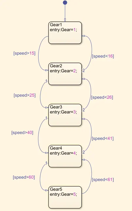
- Speed is the input and gear is the output for the stateflow.
- In 1st sate it will check if speed>15 if true transition happens to the 2nd state else the gear number is displayed.
- In 2nd state there are 2 transitions happening 1st it will check if speed>25 if true transition happens to the 3rd state, in transition 2 it will check if speed<16 if true it passes to 1st state if both conditions are false the gear number is displayed.
- In 3rd state there are 2 transitions happening 1st it will check if speed>40 if true transition happens to the 4th state, in transition 2 it will check if speed<26 if true it passes to 2nd state if both conditions are false the gear number is displayed.
- In 4th state there are 2 transitions happening 1st it will check if speed>60 if true transition happens to the 5th state, in transition 2 it will check if speed<41 if true it passes to 3rd state if both conditions are false the gear number is displayed.
- In 5th sate it will check if speed<61 if true transition happens to the 4th state else the gear number is displayed.
RESULT:
1. Washing machine
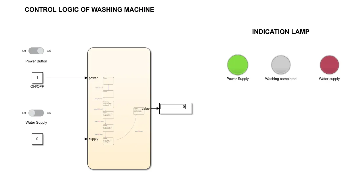
Figure shows that the system is activated when power is ON since the water supply is OFF the process cannot be completed that’s why washing completed lamp is not illuminated and water supply is indicated as red lamp because there is no water supply.
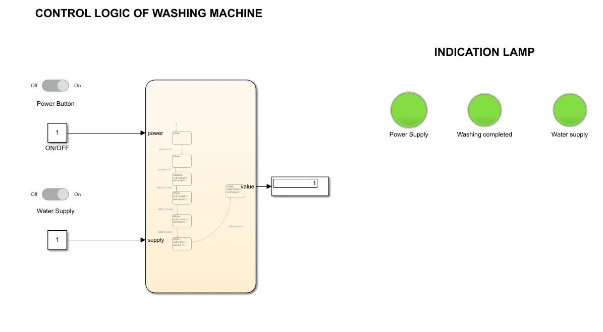
Figure shows that since the power and water supply is ON the process gets completed and washing completed lamp gets illuminated.
2. Gear Shifting
Here the speed input is varied during the running time for that the run time is set as infinite. So that we can observe the gear shift.
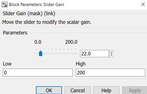
Fig: The slider is used to vary the speed
Fig: Displays the gear number for the respective speed.