Week 11 - Final project
AIM:
To design and development of vehicle interior door trim using Catia V5 with given class A surface along with Master section. Also create the Side Attachment features as per design rules.
OBJECTIVE:
- To create thickened part using master section for reference
- To create the mounting features as per design guidelines in the industry and with master sections
- To perform Draft analysis & Tooling analysis
INTRODUCTION:
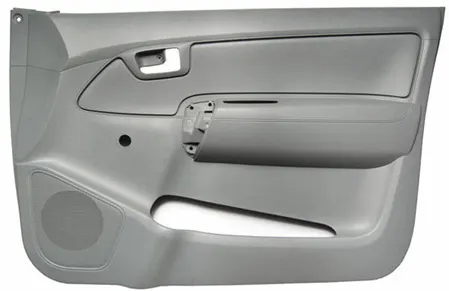
The door panel is the interface between the interior of the car and the inner workings of the door. Generally the door panel is divided into parts for easy designing like arm rest, map pocket, lower substrate. These require one of the toughest requirement among the interior parts of the car. This should be designed to with stand the load while being less than 2mm in thickness and also to protect the occupants during collisions.
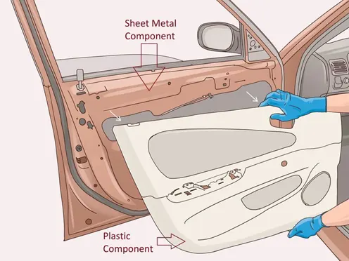
Door currently have an inner full width panel consisting of electronic windows, central locking system and speakers. These panels typically consists of a foamed core covered with either textiles or plastics.
The Final Project of DOOR TIM:
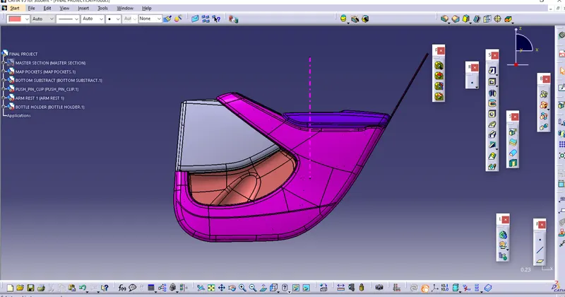
ISOMETRIC VIEW:
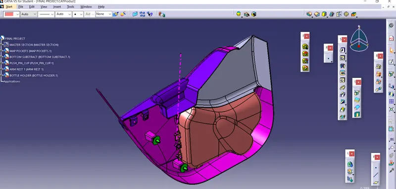
FRONT VIEW:
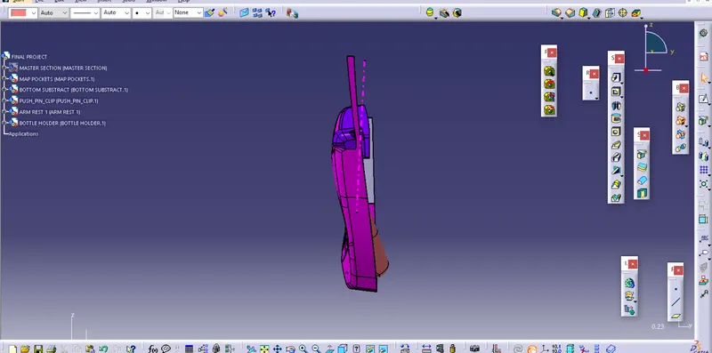
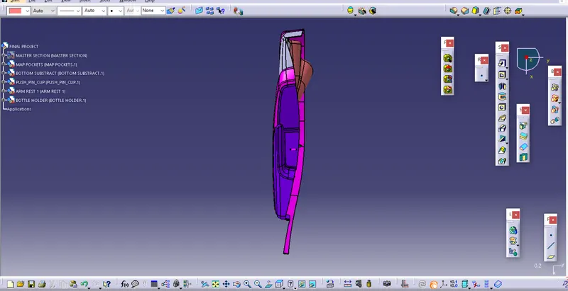
SIDE VIEW:
TOP VIEW:
Parts:
1. MAP POCKET
2. BOTTOM SUBSTRACT
3. PUSH_PIN_CLIP
4. ARM REST
5. BOTTLE HOLDER
ARM REST:
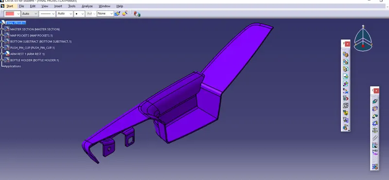
The Final part will create in following steps:
STEP - 1 CREATING TOOLING AXIS:
Tooling axis and draft analysis are explained below for arm rest.
tooling axis will be created by following steps.
tooling axis can be created in three different method.
they are: 1. X,Y,Z axis 2. Normal to the surface 3.Bisecting method.
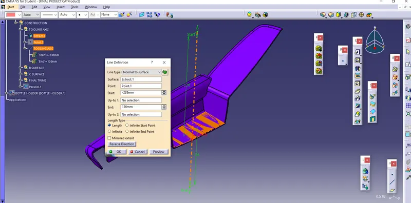
here I used Normal to the surface method.
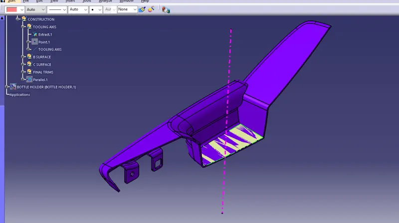
first extacted the surface and a point created as shown below.
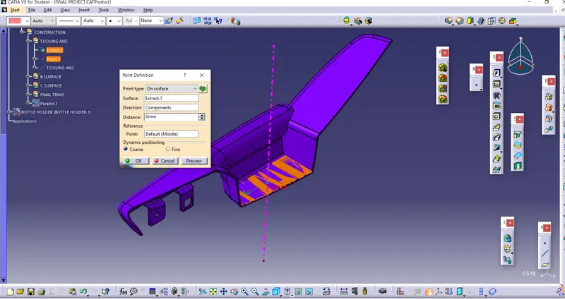
afterr a line taken normal to the surface as shown below.
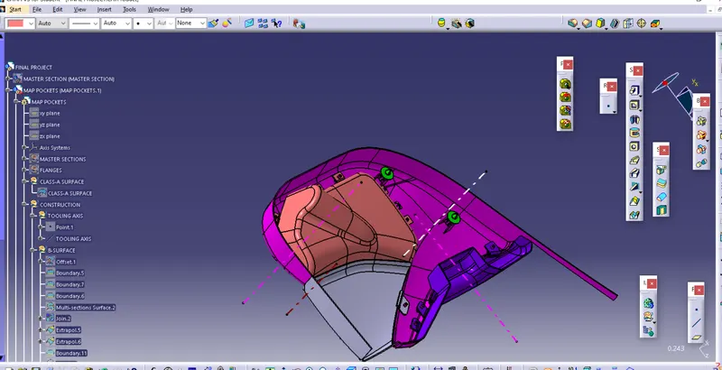
STEP -2 CREATING B-SURFACE:
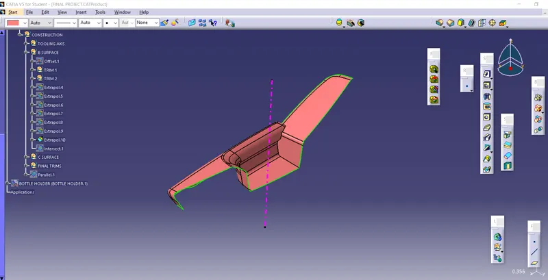
first the A- surface will be offset upto the thickness of the part 2.5mm
some parts like fillets, complex shapes won't be offset due to it's fillets radius and their shape.
so, using join command we will remove shapes and extrapolate and then trim.
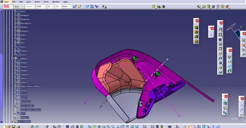
STEP - 3 CREATING C - SURFACE:
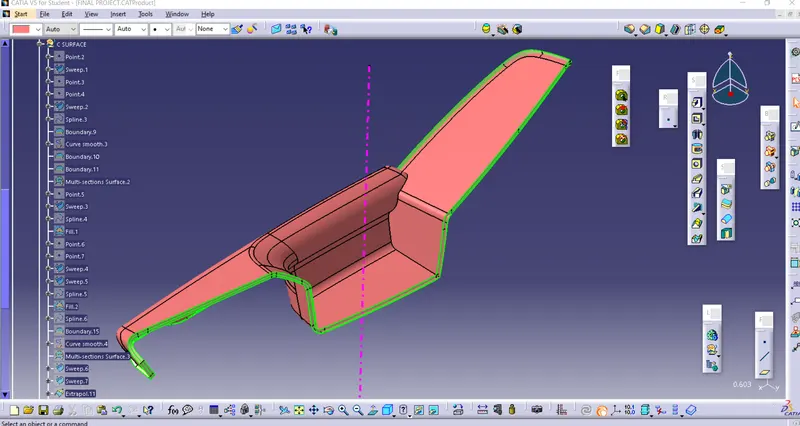
using A-Surface edges, we will create c surfaces.
STEP 4 FINAL PART BODY:
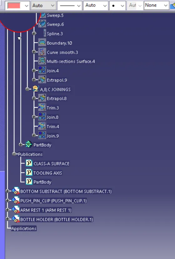
now we will join and trim A,B,C Surfaces.
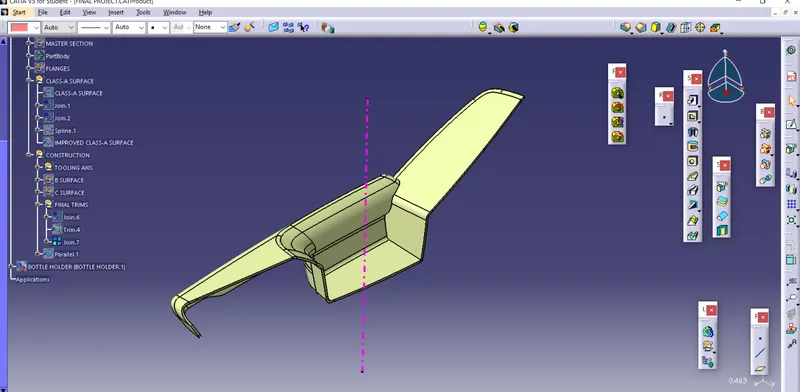
using close command we will create close body.
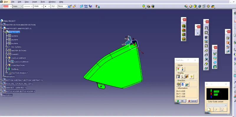
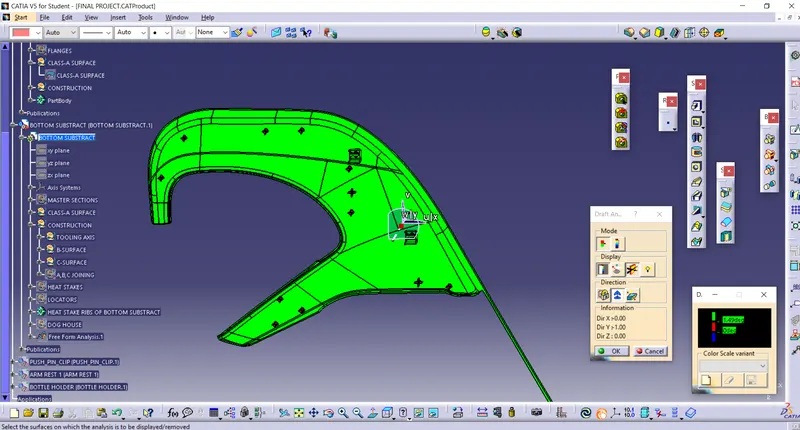
STEP 5 DRAFT ANALYSIS FOR FINAL BODY:
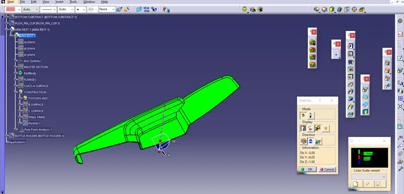
MAP POCKET ANALYSIS:
BOTTOM SUBSTRACT ANALYSIS:
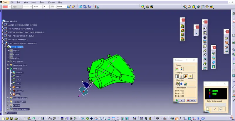
BOTTLE HOLDER ANALYSIS:
THE FINAL FEATURE TREE FOR THE PARTS GIVEN BELOW:
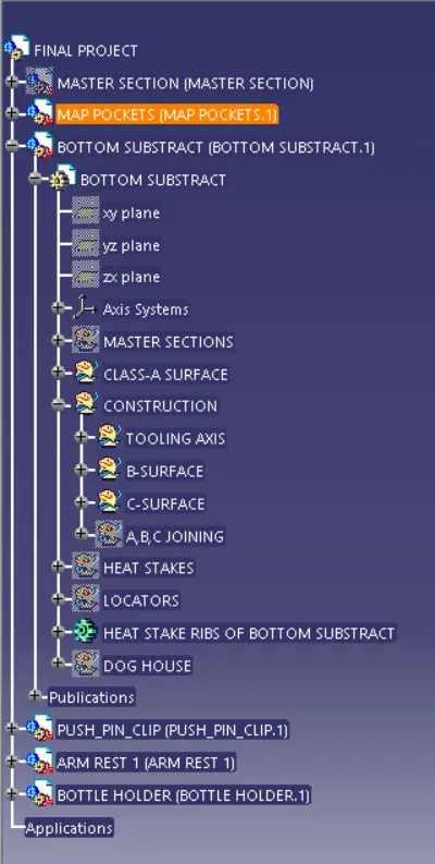
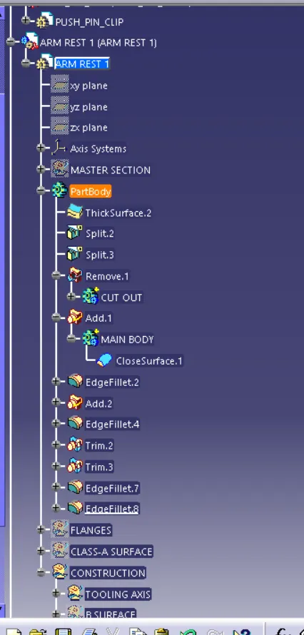
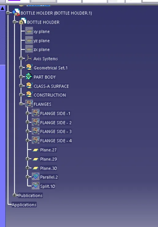
CREATING ENGINEERING FEATURES:
DOG HOUSE CREATION:
Extracting the surfaces of the part to create dog house.
Procedure to create dog house on LOWER SUBSTRATE:
Step 1: Create a point on required location and a plane from it. Create a sketch with base sketch for dog house.
Step 2: Use sweep tool to create a surface using this profile and draft direction at a draft angle of 1.5 degrees
Step 3: Use extrapolate and extrude option to create required surfaces and use trim and split to obtain the outer body of dog house.
Step 4: Create a new body and name it as dog house. Use thick surface option to create a solid of required thickness.
Step 5: Translate the dog house to required height using translate option and use thick command to extend the base surface to intersect the lower substrate.
Step 6: Extract the inner base edge and create a surface to get the required base profile. Use thick surface to create a solid and use Boolean operation to remove it from the base of dog house.
Step 7: To create top profile for attachment of push pins, create a sketch, extrude it and split it from the solid using split option
geometrical set for creating DOG HOUSE shown below.
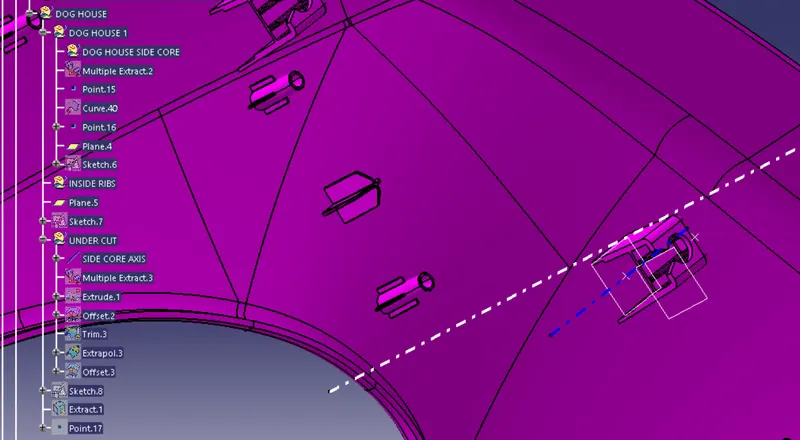
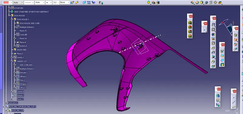
Final dog house for part:
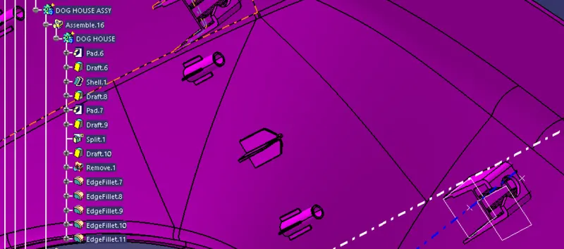
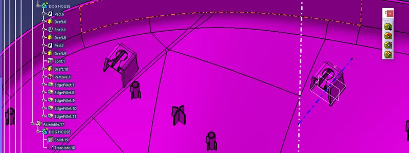
we can translate this dog house for different place using TRANSLATE Command.
HEAT STAKES:
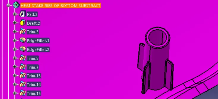
Heat stakes are used to permaenant attachment.
CREATING HEAT STAKES:
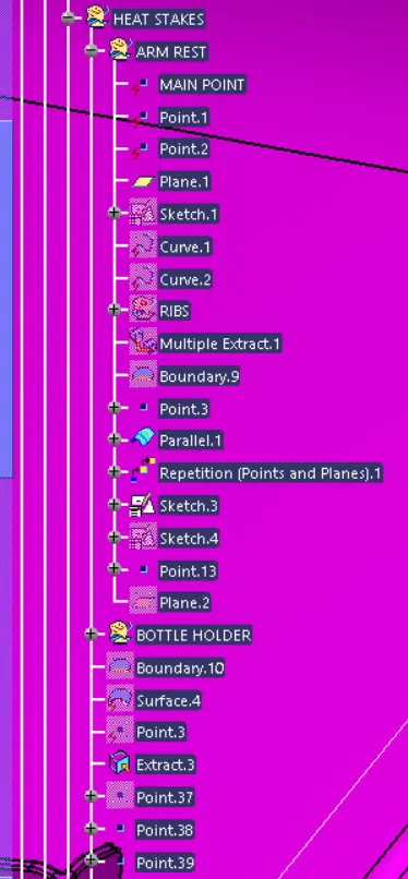
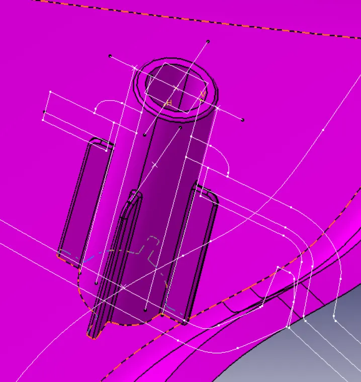
using sketch we will create a circle at a point taken from master section.
and creating plane using point and reference plane.
sketching it and pad it and then drafting it for 0.5 degrees.
creating ribs from the master section for heat stakes.
ribs will be created using the lines and pading them and then drafting.
the final heat stake shown below.
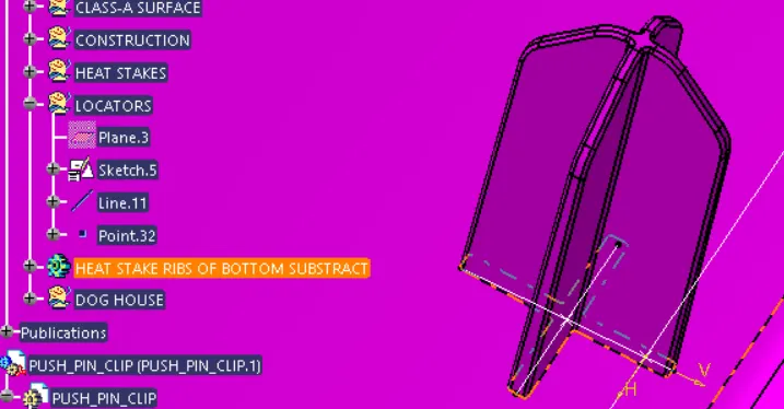
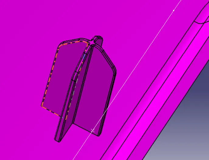
4 - WAY LOCATORS:
locators will be created for better alignment when assembling the parts and to locate the heat stakes places exactly.
sketch the lines as shown below and pad them by selecting thick command and draft them.
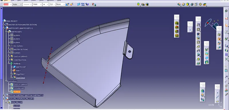
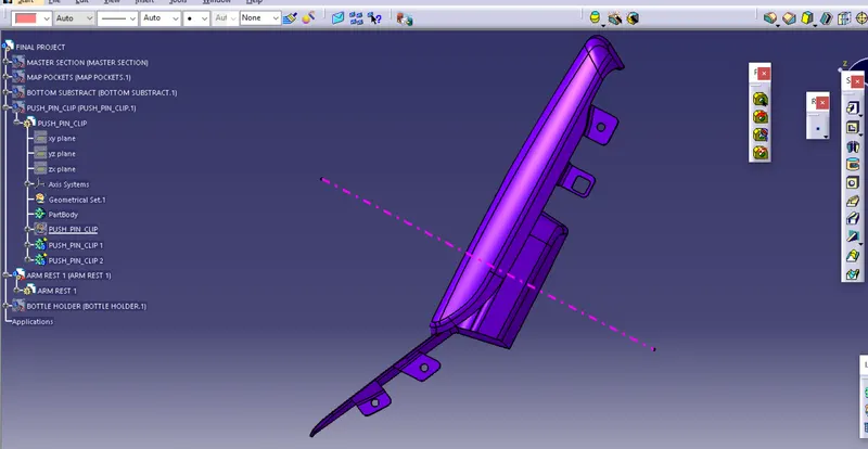
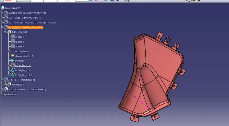
FLANGES:
Flanges are created to assemble accurately with other parts.
FLANGES OF MAP POCKET:
FLANGES OF ARM REST:
FLANGES OF BOTTLE HOLDER:
CONCLUSION:
The CAD model considering following inputs as like in OEM and tier1 companies is created.