Week 11 - Final project
Note: Detailed final project explanation have been attached in the zip file given below
Arm rest
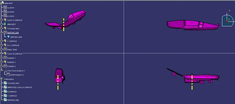
Class A surface
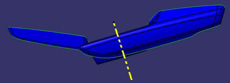
Class B surface
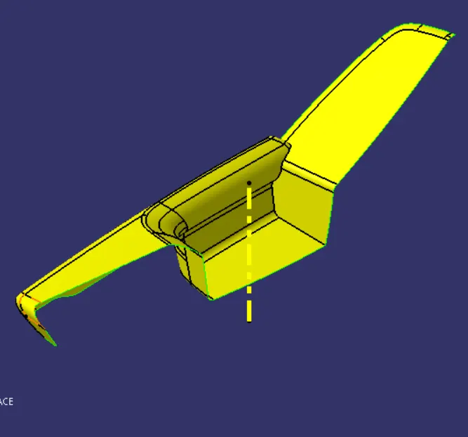
Class C surface
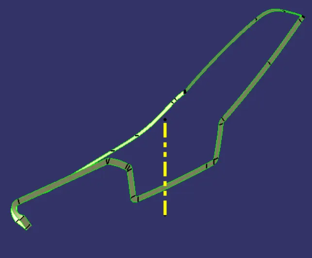
Lower substrate
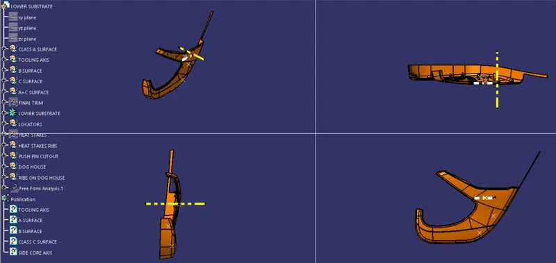
Class A surface
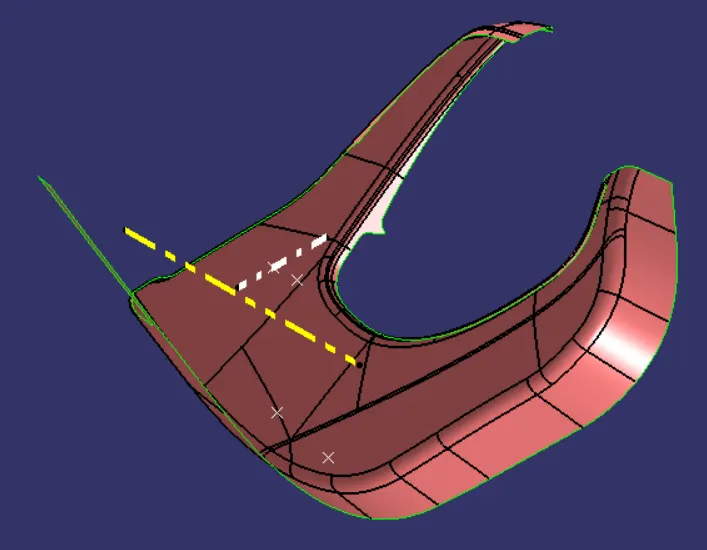
Class B surface
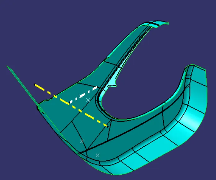
Class C surface
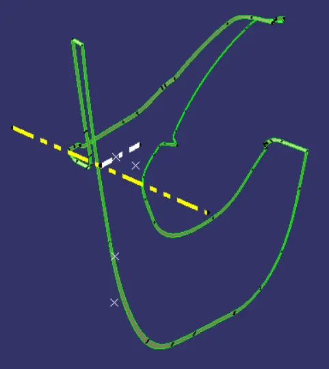
Map pocket
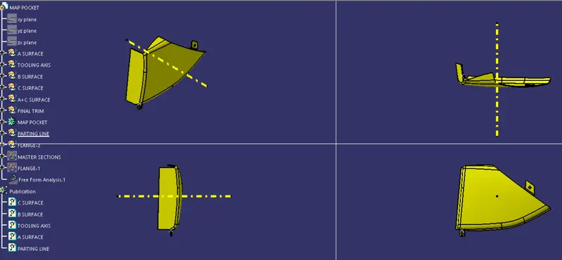
Class A surface
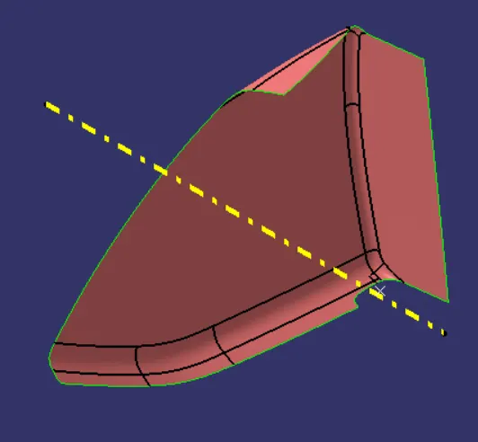
Class B surface
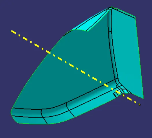
Class C surface
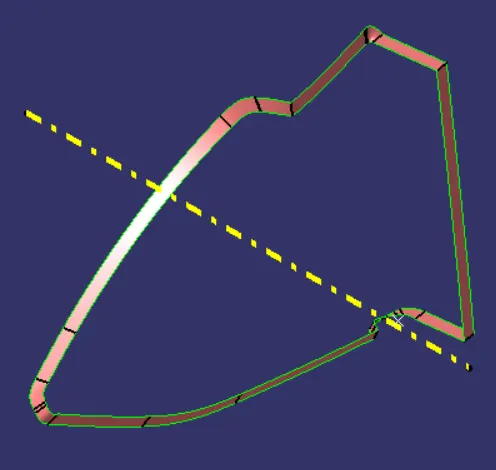
Bottle holder
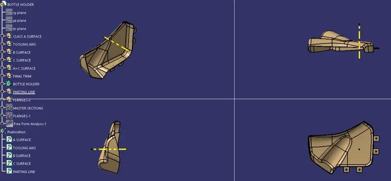
Class A surface
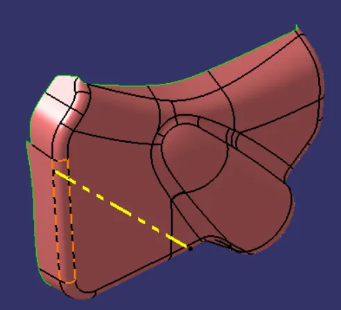
Class B surface
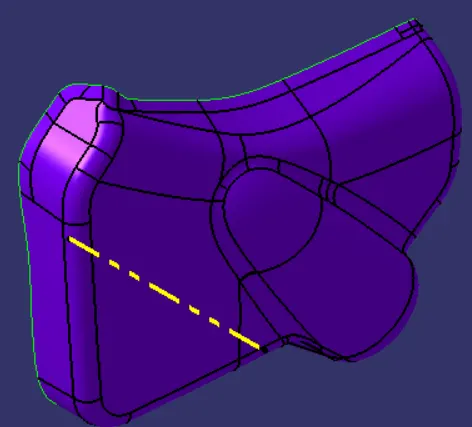
Class C surface
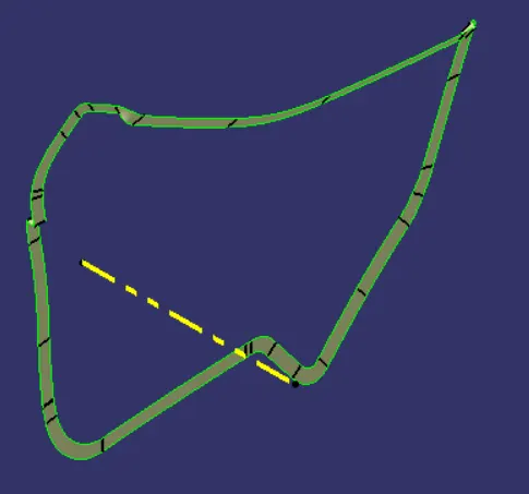
Explanation for tooling axis and it procedure
Tooling axis is an axis in which the mold or core and cavity opens.
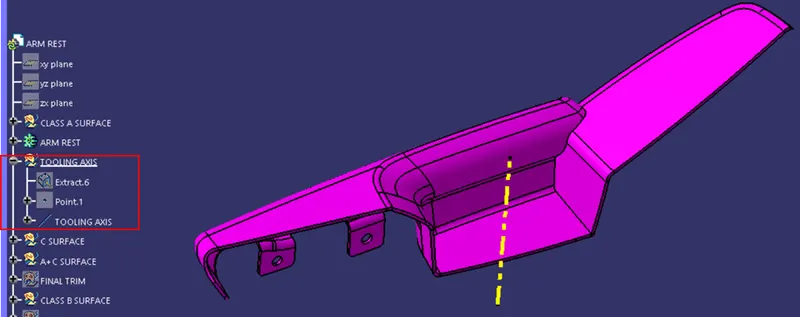
Creation of tooling axis: The following are the steps to create core and cavity,
1.First step is to look from which direction we can able to create the tooling axis i.e whether in X, Y or Z direction; always prefer the direction which a part can be fully visible/ partially to us.
2.The next step is to extract the surface followed by creating a point on the surface.
3.Then by using point-direction option a line is created for tooling axis.
Eg. In arm rest
Draft analysis
Draft is a taper applied to the faces of the part that prevent them from being parallel to the motion of the mold opening. This keeps the part from being damaged due to the scraping as the part is ejected out of the mold.
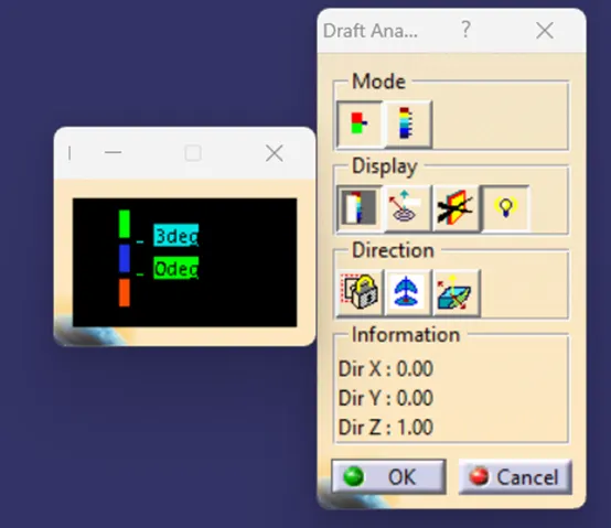
Draft analysis procedure: The following are the steps to do the draft analysis,
1.Place the compass normal to the tooling.
2.Click the compass option in draft analysis dialog box, again the compass will be aligned in some direction.
3.Again repeat step 1 and lock the compass using lock option in dialog box.
4.Click on the surface of the part to perform the draft analysis.
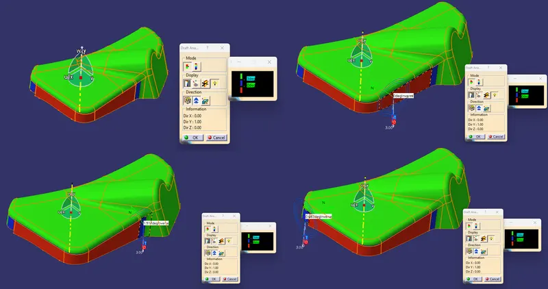
Arm rest (Class A surface)
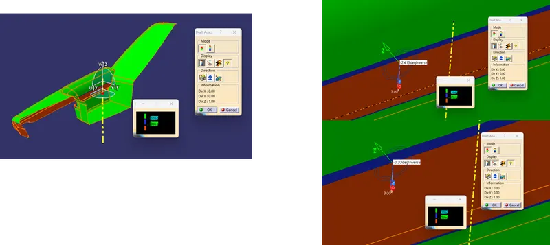
Inference of draft analysis on class A surface: The red highlighted area shows negative draft and blue color area denotes 0° draft
Conclusion: Since in class A surface itself we can see a negative draft, so this must be reported to class A surface engineer
Arm rest (closed surface)
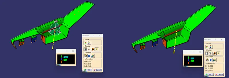
Inference: Since we can see a negative draft in class A surface, it is reflecting on closed surface and 3° draft angle is given and it is passing on almost all the core side; red color denotes negative angle and blue color denotes 0°
Flange areas: Since I have followed the master section to create the flanges, it is creating the negative draft
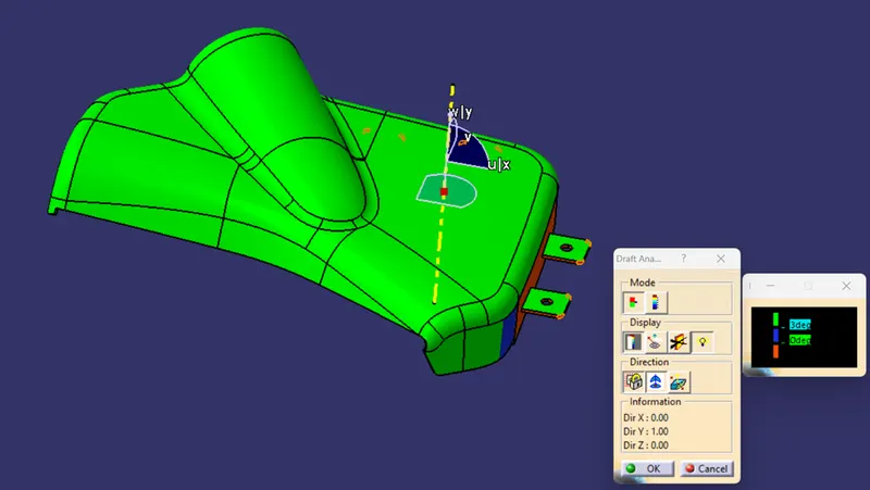
Bottle holder (class A surface)
Inference of draft analysis on class A surface: The red highlighted area shows negative draft and blue color area denotes 0° draft
Conclusion: Since in class A surface itself we can see a negative draft, so this must be reported to class A surface engineer
Bottle holder (closed surface)
Inference: Since we can see a negative draft in class A surface, it is reflecting on closed surface and 3° draft angle is given and it is passing on almost all the core side; red color denotes negative angle and blue color denotes 0°
Flange areas: On the core side, it is having the positive draft of 3°
Map pocket (Class A surface)
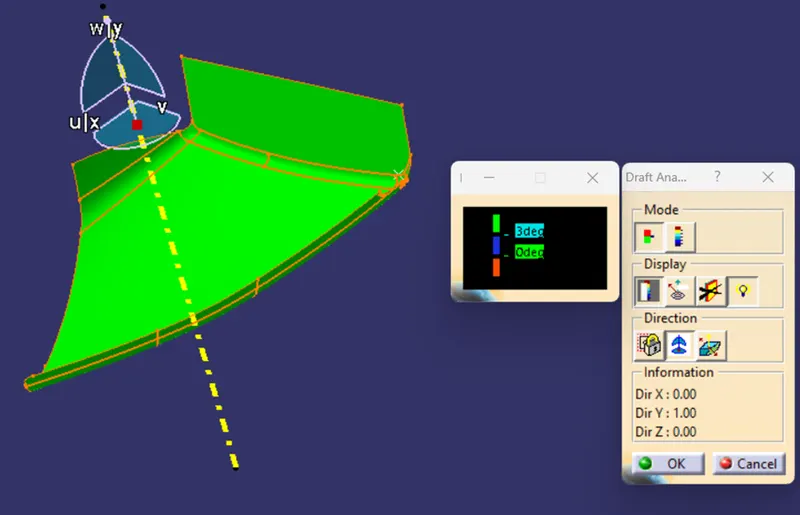
Inference: As there is no red or blue color, the class A surface is good as there is no negative draft
Map pocket (Closed surface)
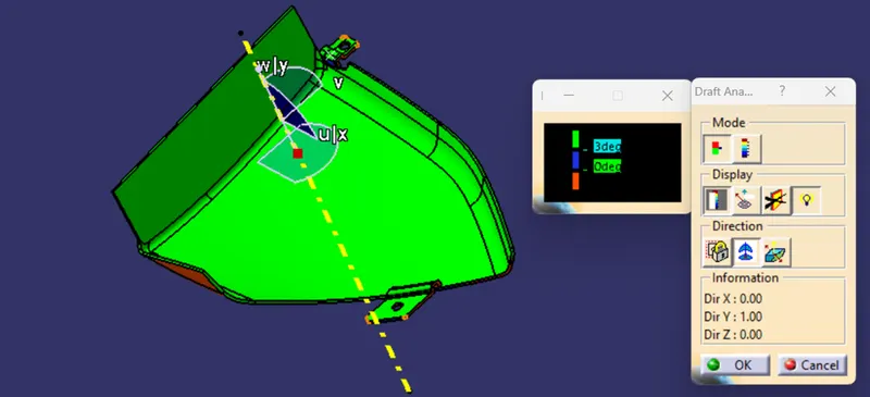
Inference: The green color indicates that there is no negative draft angle
Flange areas: On the core side, it is having the positive draft of 3°
Lower substrate (Class A surface)
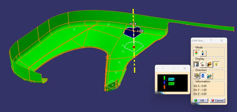
Inference: As there is no red or blue color, the class A surface is good as there is no negative draft
Lower substrate (closed surface)
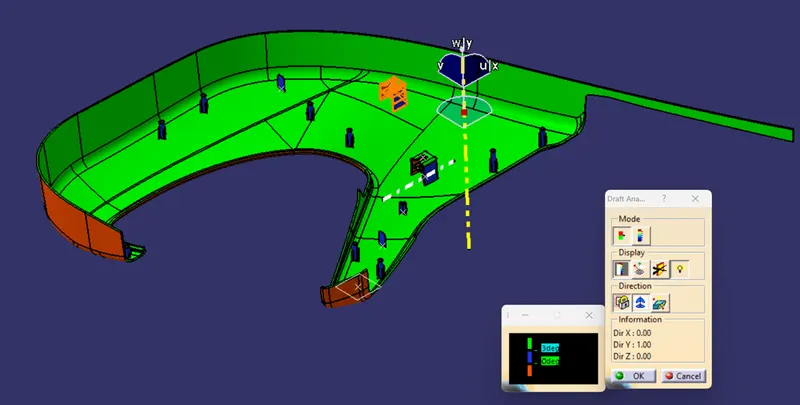
Inference: The green color indicates that there is no negative draft angle
Engineering features: On the core side, it is having the positive draft of 3°
Dog house:
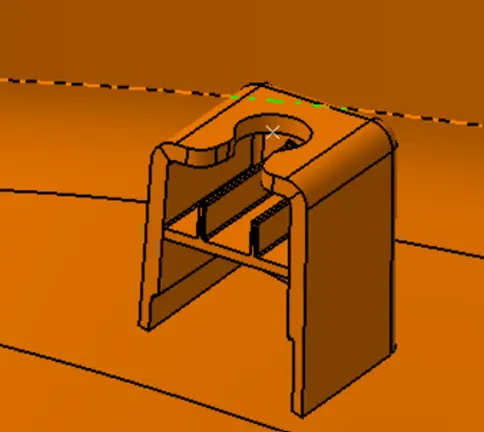
Dog house is an engineering feature used in plastic trim design. Dog houses are used as supporting feature.
Sometimes other engineering features like snaps; locators etc. are mounded on them to increase their strength.
Dog houses are subjected to draft analysis to prevent breakage of the component during ejection from mold cavity.
Dog house and other engineering components are built on B-surface.
Dog house design guidelines
Dog houses are designed to avoid SINK MARK created on the CLASS-A surface by screw bosses and to solve the length issues
when giving screw bosses which need to be assembled to other components. It is also useful when perpendicular screw bosses
are required on the part to the tooling direction.
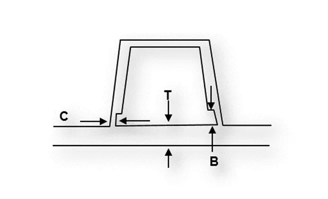
- C thickness should be 40% of the main wall thickness T
- Minimum width of the dog house is 12 mm.
- Height of B should be 3-6 mm
- Minimum draft for the do house is 1.5 degree to die draw
Side core axis and its purpose
The molded side hole or the undercut part must be made into a movable core. And the movable core is taken out before the plastic part is pushed out. It is an automatic pulling mechanism.
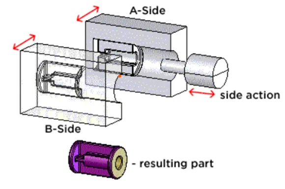
These are standard off-the-shelf mold components that are designed into the mold to push against a surface of the part to push the part off of the ejector half of the mold—commonly called the core side, sometimes referred to as the ejector half, or the moving half, or the “B” side of the mold.
Procedure for creating side core axis: The following are the steps to create the side core axis,
1.Extract a surface from the part and create a point
2.In that point, create a plane using parallel thro point option
3.Using line option, create a line in y-axis thro the created point
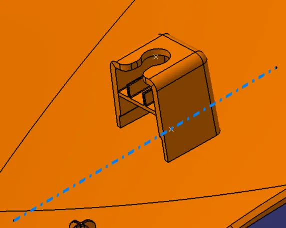
Draft analysis on dog house
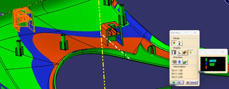
Inference: Dog house will have a draft angle of 1.5°. Thus the picture above shows that it is clearing on the core side with 1.5°
Heat stakes:
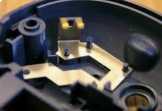
Heat staking also known as thermoplastic staking is the process of joining two dissimilar materials together. In heat staking we use local heating and cooling to raise the temperature of plastic components and allow plastic reforming to be carried out. This reforming can be used in a wide variety of applications. Applications range from staking plastic bosses for assembly of car door panels to joining PCB’S to plastic housings. Benefits of this technique include; no vibration damage, no particulates, the ability to stake metalized coated applications and the capability to stake in difficult to access or restricted areas.
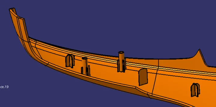
Industry Applications:
- Automotive : Reliable solution for interior parts, welding bumpers, tail light assemblies, dashboards & many more parts
- Textile: Creates durable seals without the need for glues, clips and yarns in product designs
- Appliances: Component welding for large or small household appliances
Locators
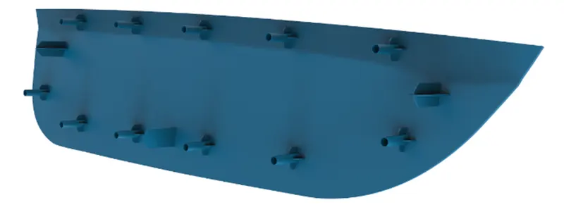
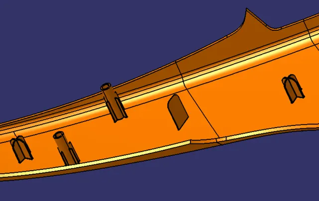
Locators provide a positive stop for the workpiece. Placed against the stop, the workpiece cannot move. Clamps, on the other hand, rely only upon friction between the clamp and the clamped surface to hold the workpiece. Sufficient force could move the workpiece.
4 way locator:
A round locating pin located concentrically in a hole is a common application of a 4-way pin and helps to further secure the piece. 4-WAY LOCATORS: 4-way mean you prevent movement at 2 axes (+X, -X, +Y and -Y) on the plane. Generally, you have cylindrical pin on the fixture and circular hole at workpiece part.
2 Way Locator:
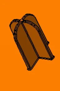
A 2-way locating pin restricts motion along 1 axis (or 2 degrees of Freedom), like a round pin in a slot. Likewise, a 4-way pin restricts 4 degrees of freedom along 2 axes.
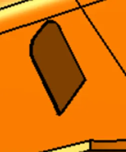
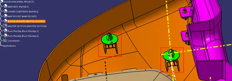
Assembling of push pin into the dog house
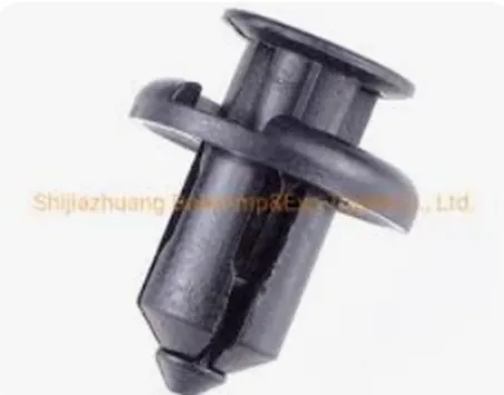
Push clips are widely used for trim panel clips, door trim clips, door panel clips, bumper clips, Fender clips, engine cover and splash shield retainer's replacement. It always covers some applications include telecom equipment, motor vehicles, domestic appliances, furniture and electrical equipment.
Parting line and its procedure to create
A parting line is the line of separation on the plastic part where the two halves of the plastic injection mold meet. The line actually indicates the parting plane that passes through the part. The location of a plastic parting line is determined both by mold function and part function. The parting line is where the mold opens, so easy ejection from that point is required. It may also be visible and affect the functionality of the final part.
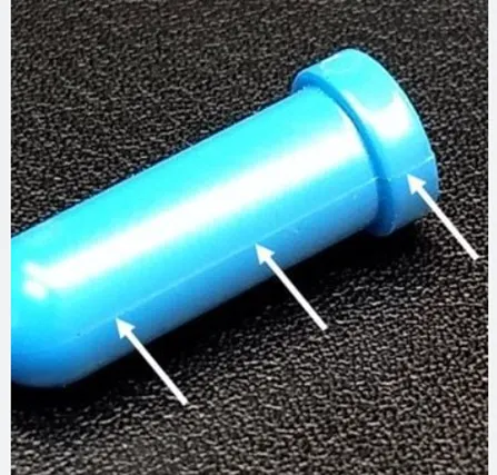
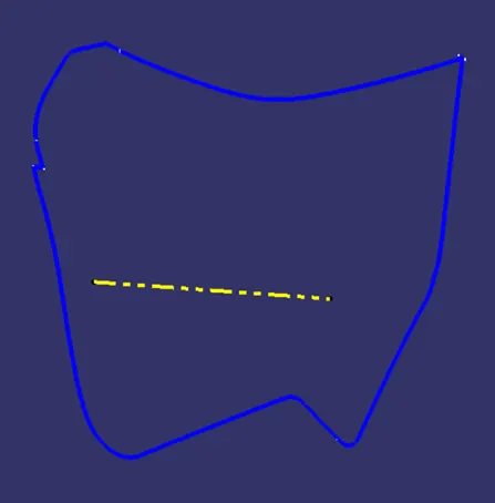
Parting line is created by intersection of B & C surfaces
Material mode selection
All the five parts have been selected with each material,
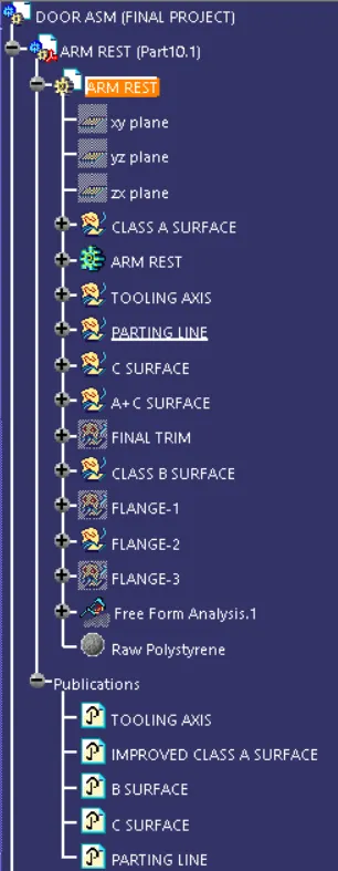
1. Arm rest - Raw polystyrene
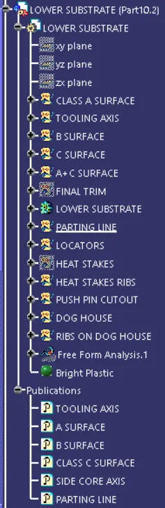
2. Lower substrate - Bright plastic
3. Map pocket - Flat polystyrene
4. Bottle holder - Plastic
5. Push pin - Nylon
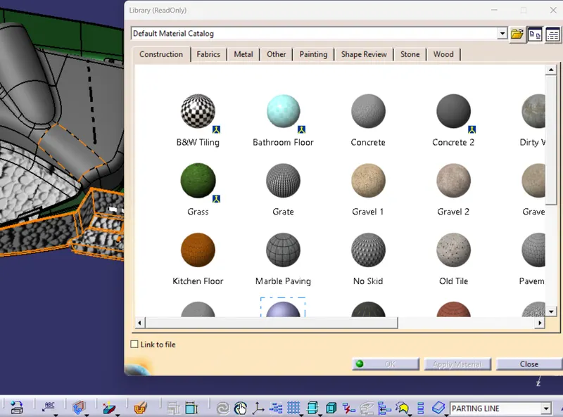
Procedure for selecting material:
Select View > Render Style > Customize View command then select the Material check box or click Shading with Material
in the View Toolbar.
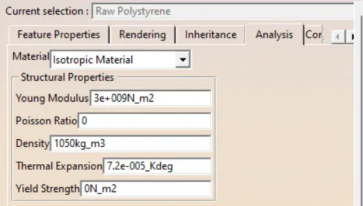
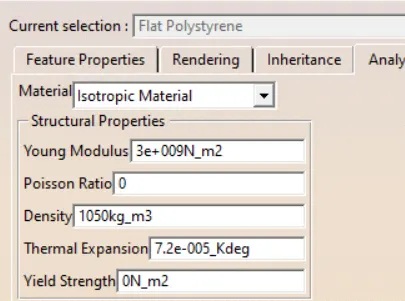
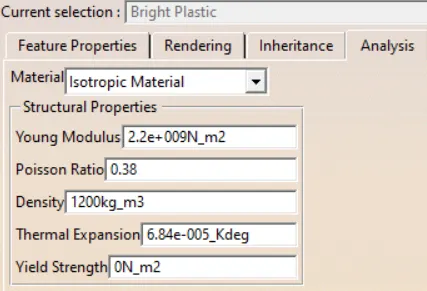
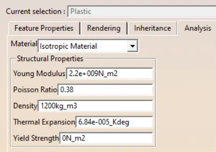
Material selection
Non detailed model tree:
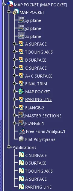
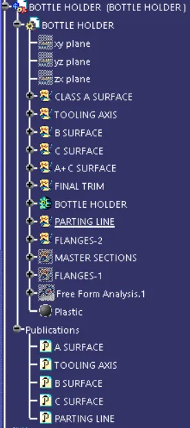
Conclusion: Thus we have created closed surfaces of door panel components with engineering features and flanges. Also drfat analysis and material selection have been done for individual parts.