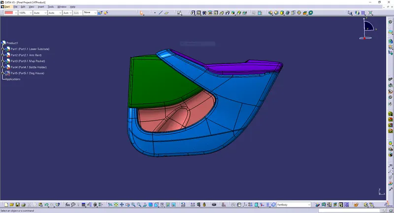
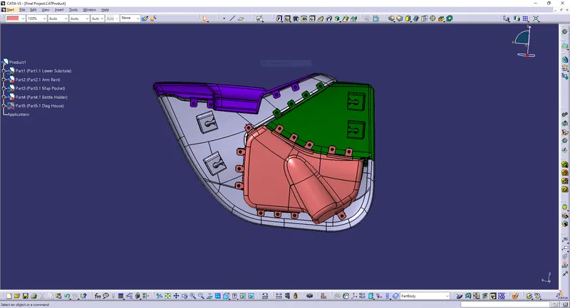
Week 11 - Final project
REPORT FOR DOOR PANEL DESIGN:
Aim : To create the Door Panel Plastic component through the given Class-A surface.
- Creation of CAD model considering following inputs as like in OEM and tier1 companies
a) Class A surface
b) Nominal thickness : Refer master sections
c) Attachment strategy : Use heat stakes for part to part attachment
- To create the tooling axis for the given Class-A Surface meeting the requirements of the draft angle and at the end perform the Draft analysis on the final model.
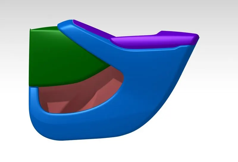
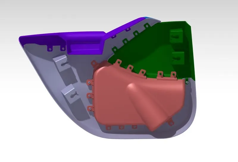
Introduction:
A Door Trim Panel is an interior component attached to the inner side of the door. This product does more than merely improve the appearance of the vehicle interior. Rather, it is a vital module component that creates a more comfortable interior by providing a variety of accouterments and functions. As such, there is a necessity for balancing gap between parts, as well as an overall sense of unity between the numerous parts. They are expected to meet a variety of design specifications regarding safety, aesthetics, and functionality. Doors currently have an inner full-width panel consisting of arm rest, map pocket, bottle holder, electronic windows, central locking system, and speakers. These panels typically consist of a foamed core covered with either textiles or plastics.
Design Methodology:
The input of the product designer is in the form of the Class A Surface and Master Section. The job of the product designer is to create the B and C surfaces and using the Master Section create the attachment features keeping all the aspects for the mold.
Creation of Tooling Axis:
The tooling axis is the direction of drawing a sheet metal where the finished component is easily ejected on a particular direction and axis. In Molding, machine arrangement is given to open the mould along a direction which is known as Tooling Direction. In other words. The mould is built from two separate halves (Core and Cavity) and tooling direction basically defines the direction of mould pulls apart.
Material Selection
The material can be used for manufacturing Door Panel is Acrylonitrile Butadiene Styrene (ABS). Because of its some features such as:
- The styrene provides the copolymer with a shiny, tough exterior.
- Provides quality surfaces and good resistance to chemical agents.
- A wide variety of adjustments can be made to enhance impact resistance, durability and heat resistance.
Also the Polyoxymethylene material can be used to manufacture the Door trim. It has the features called: high rigidity, yield strength and high stability in cold temperatures. Highly chemical- and fuel-resistant. Also POM is used to fabricate interior and exterior trims.
For manufacturing Door Trim component the injection molding method can be adopted. It would be the right manufacturing method. Because it is a right way to create the exact moulding for the required product. This is a common method is used to produce a high volume of plastic parts of automobiles. Products can also be made with increased flexibility to suit the needs of designers or engineers.
Class A,B & C Surface
Class A Surface:
It is the outermost aesthetic surface which is visible to customers (the outermost visible surface of a product).
Class B Surface:
It is the offset of the class A surface at a particular distance. The offset distance depends on the thickness between Class A and Class B surface. In Class B Surface, where the attachment features are built in and attached.
Here, the thickness given is = 2.5mm.
Procedures to build class B surface:
- Offsetted the joined surfaces from class A to 2.5mm inorder to create class B surface.
- Extrapolated the offseted surfaces inorder to make sure all the surfaces are in contact.
- Trimmed the offsets to get an output same as class A surface
- Fillets are given to the required edges based on the thickness and curvature of the class A fillets.
Class C Surface:
This surface connects the Class A and Class B surfaces. (Surface in between Class A & B surfaces)
Procedure to build Class C surface:
- Boundary of class A surface is extracted and then smoothcurved the boundaries if its required
- Also if needed Multi-Section Surface command can be used to create the Class C Surface
- Then that boundary is swept along with respect to Tooling Axis until it gets coincided with the offseted class B surface.
- Or else the boundary is swept perpendicular to the Class A Surface until it gets coincided with the offseted class B surface.
- Both the sweep surface and multi-section surface are joined together to form as a single one.
Joined and Closed Class A,B & C surface:
After creating class B & C surfaces, joining operation is done between class A and class C surfaces. Then, Class B surface is trimmed with joined Class A & C surfaces to get a whole closed single surface. Then in the part workbench using closed body command, a solid body is generated.
Attachment of Engineering Features:
- Flanges
These flanges will be build on the components for the fittment purpose with lower substrate.The hole at center will be guided along the heat stakes. Later top portion of the heat stake will be melted over it. The flange should rest on the supporting ribs on side. Flanges are a non-contact welding process
- Heat Stakes:
Heat staking also known as thermoplastic staking is the process of joining two dissimilar materials together. In heat staking we use local heating and cooling to raise the temperature of plastic components and allow plastic reforming to be carried out. Application ranges from staking plastic bosses for assembly of car door panels to joining PCB’s to plastic housings. Benefits of this technique include; no vibration damage, no particulates, the ability to stake metalized coated applications and the capability to stake in difficult to access or restricted areas.
- Dog House:
Dog house is an engineering feature used in plastic trim design. Dog houses are used as supporting feature. Sometimes other engineering features like snaps, locators etc. are mounded on them to increase their strength. Dog houses are subjected to draft analysis to prevent breakage of the component during ejection from mould cavity. Dog house and other engineering components are built on B-surface.
Draft Analysis:
In the criteria of making a plastic material, the mold should release the material when finished. if the mold surfaces are 90 degrees the material won't release from the mold because of friction due to contraction of material when cooled.The ejection of the part from mold depends on the draft. A zero draft can result in difficult or no ejection. It is recommended to add a draft of 3 degree or above inorder to remove it from the mold without any damage.
Procedure To Built The Door Panel:
The Door Panel consist of the following parts:
- Lower Substraite
- Arm Rest
- Map Pocket
- Map Pocket With Bottle Holder
1. Lower Substraite:
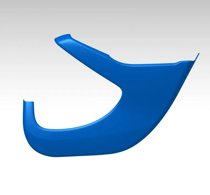
Creation of Tooling Axis:
- For creating tooling axis here in the given model Lower Substraite, used the Normal To Surface method.
- For creation of tooling axis, one of the surface is extracted and a point is inserted on the extracted surface, through which tooling axis is drawn.
Class A surface with Tooling Axis:
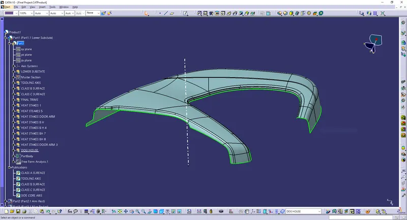
Draft Analysis of Class A Surface:
Checking the Draft Analysis for the Class A surface with respect to created Tooling Axis. To ensure the created Tooling Axis is in correct way.
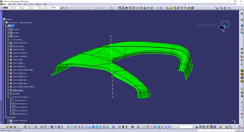
Here in the above image it is clearly shows the Class A Surface is not having any negative draft. Therefore the Class A Surface is not having any irregularities.
Creation of Class B Surface:
Here, the thickness given is = 2.5mm. So the given input Class A Surface is offseted to 2.5mm to obtain the Class B Surface.
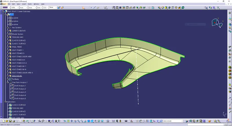
Creation of Class C Surface:
- Boundary of class A surface is extracted and then smoothcurved the boundaries if its required
- Also here Multi-Section Surface command is used to create the Class C Surface
- Both the sweep surface and multi-section surface are joined together to form as a single one.
- Then that boundary is swept perpendicular to the Class A Surface until it gets coincided with the offsetted class B surface.
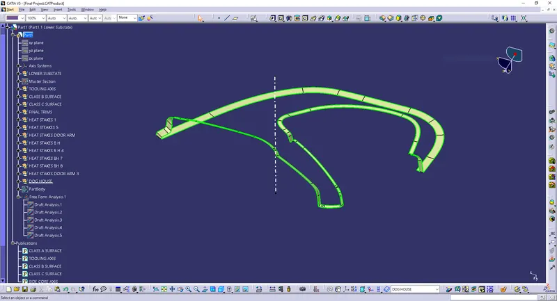
Enclosed Surface Creation:
Closed Body:
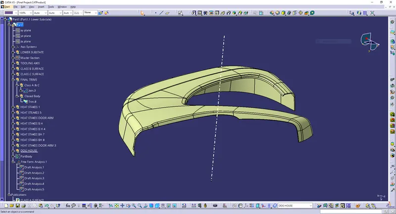
Attachment of Engineering Features Creation Using Master Section:
Heat Stakes
- Heat Staking is a pulsed-heat process to join two or more parts out of which one at least is made of plastic.
- The process is to deform the plastic material using heat and force at a set process time.
- The bond is made by partially de-forming the plastic part in order to fix the other.
- Heat Staking makes it easy to bond metal to plastic and is commonly used in high volume/low cost applications such as automotive, IT and consumer appliances.
- Similar and dissimilar materials may be joined: metal to metal, plastic to plastic, metal to plastic
- Accurate control operating within a small process window
- Local heating resulting in no damage to surrounding materials
- Processing of glass-filled materials
- No mechanical vibration
- Many heat-stake shapes possible through custom designed tools.
Ribs attached To Heat Stakes
- The ribs provide economical stiffness and strength to the part without increasing the overall thickness of the part.
- The ribs are used as locating and arresting in the assembly as locators.
- Proper allignment in mating parts, slot and rib pair is long lasting other than screw pair which loosen up with time.
- Acting as stops or guide for mating the tilted headlamps.
- Rib designs includes: thickness, quantity, height , manufacturibility and location.
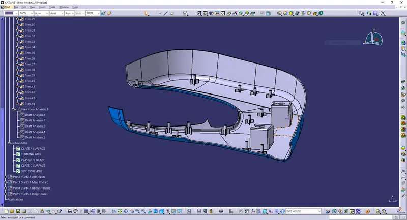
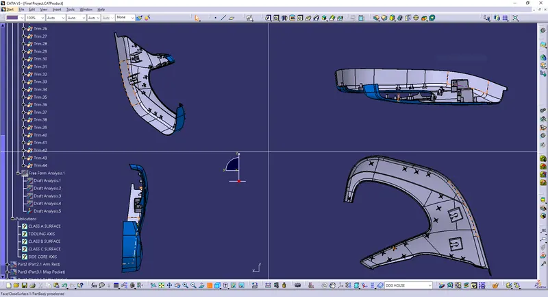
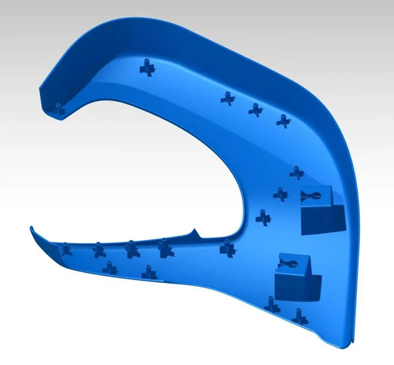
Solid Body with Attachment Feature:
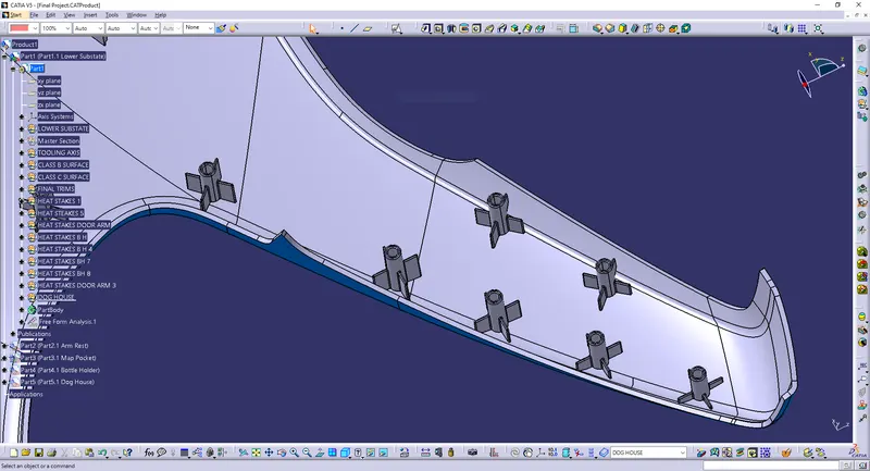
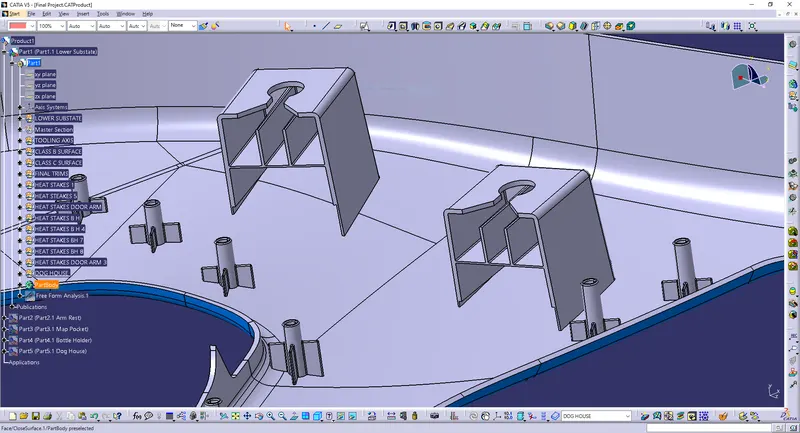
Final Model:
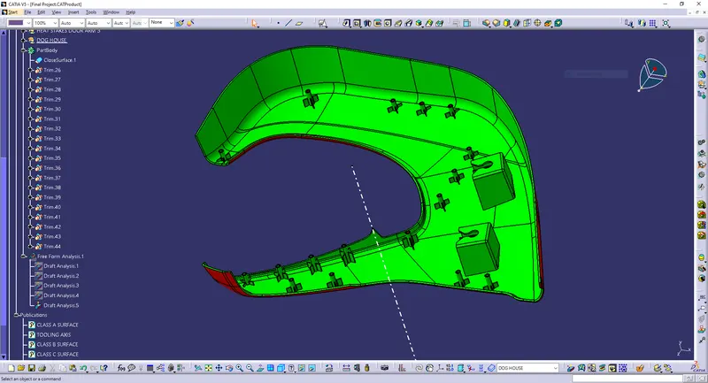
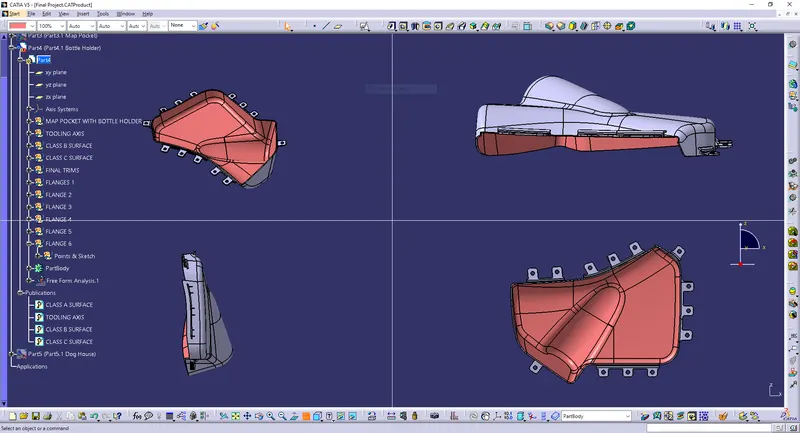
Draft Analysis:
Procedure:
- Change the view mode to customize view parameters and give material as view mode.
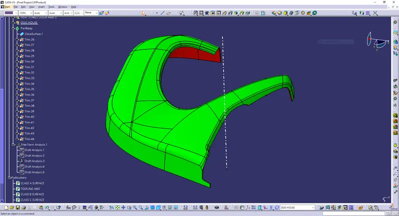
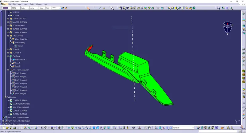
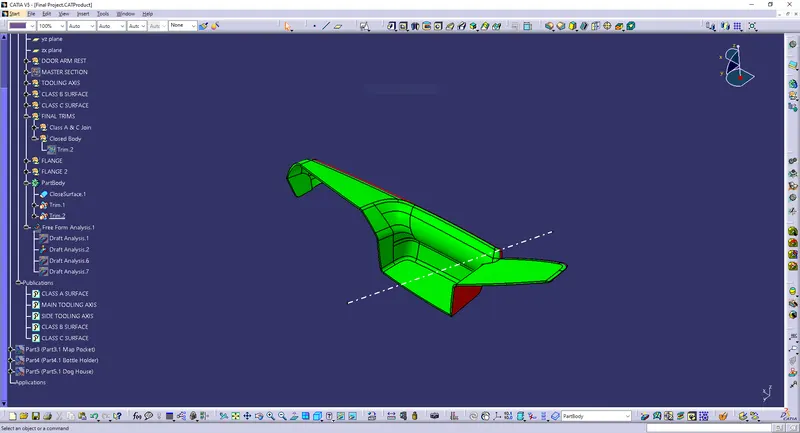
- In the draft analysis toolbar, set the draft values and color (3 degree and above - green, 0 to 3 degree - blue, less than 0 - red).
- Drag and drop the axis system on the tooling axis and lock it.
- Perform draft analysis.
2. Arm Rest:
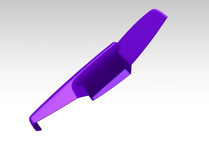
Creation of Tooling Axis:
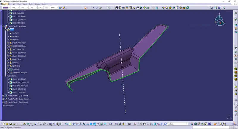
- For creating tooling axis here in the given model Lower Substraite, used the Normal To Surface method.
- For creation of tooling axis, one of the surface is extracted and a point is inserted on the extracted surface
- Through the point the tooling axis is drawn.
Class A Surface with Tooling Axis:
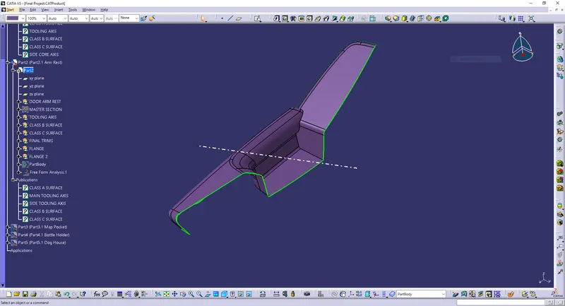
Class A Surface with Side Core Tooling Axis:
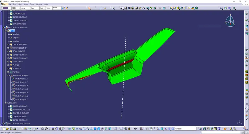
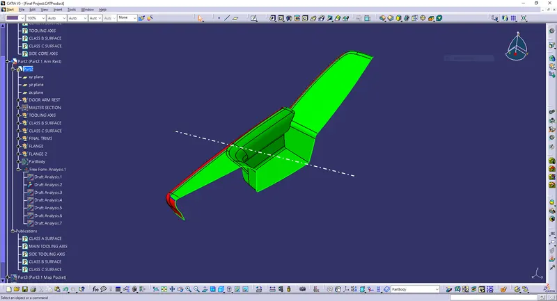
Draft Analysis of Class A Surface:
Checking the Draft Analysis for the Class A surface with respect to created Tooling Axis. To ensure the created Tooling Axis is in correct way.
Draft Analysis of Class A Surface with main tooling axis:
Draft Analysis of Class A Surface with side core tooling axis:
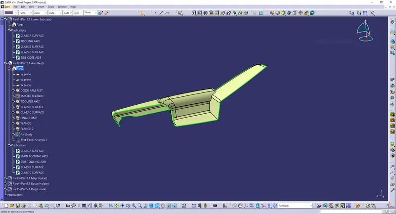
Creation of Class B Surface:
Here, the thickness given is = 2.5mm. So the given input Class A Surface is offseted to 2.5mm to obtain the Class B Surface.
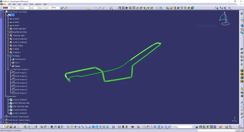
Creation of Class C Surface:
- Boundary of class A surface is extracted and then smoothcurved the boundaries if its required
- Also here Multi-Section Surface command is used to create the Class C Surface
- Both the sweep surface and multi-section surface are joined together to form as a single one.
- Then that boundary is swept perpendicular to the Class A Surface until it gets coincided with the offsetted class B surface.
Enclosed Surface Creation:
Closed Body:
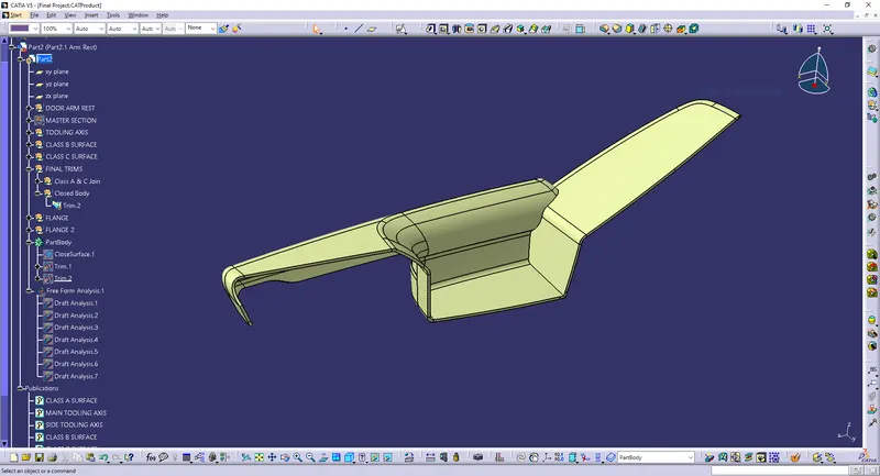
Attachment of Engineering Features Creation Using Master Section:
Flanges
- These flanges will be build on the components for the fittment purpose with lower substrate.
- The hole at center will be guided along the heat stakes.
- Later top portion of the heat stake will be melted over it.
- The flange should rest on the supporting ribs on side.
Solid Body with Attachment Feature:
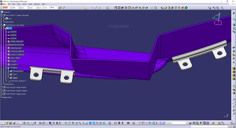
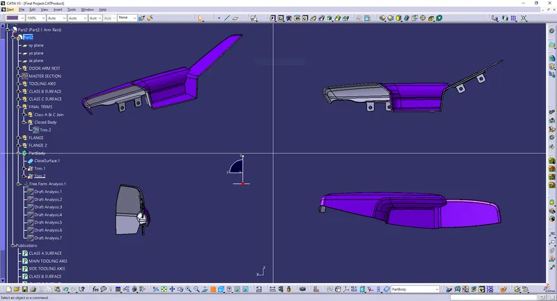
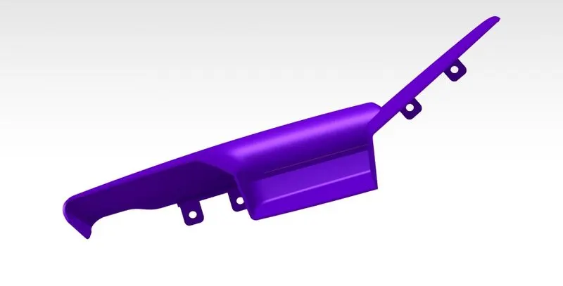
Final Model:
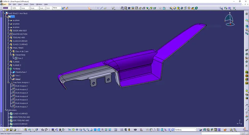
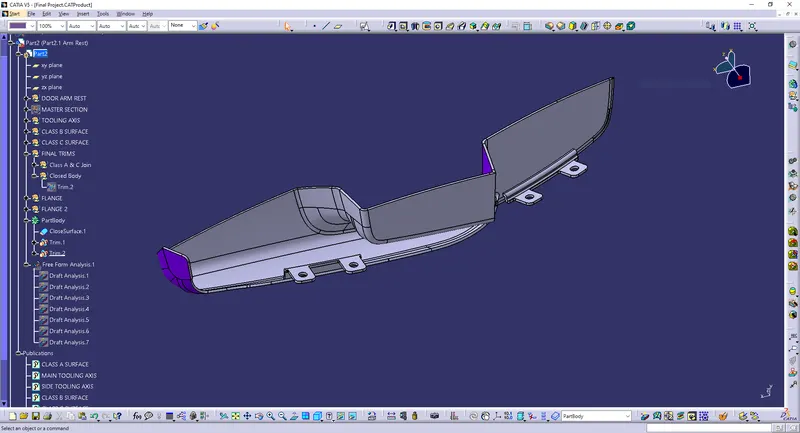
Draft Analysis:
Procedure:
- Change the view mode to customize view parameters and give material as view mode.
- In the draft analysis toolbar, set the draft values and color (3 degree and above - green, 0 to 3 degree - blue, less than 0 - red).
- Drag and drop the axis system on the tooling axis and lock it.
- Perform draft analysis.
3. Map Pocket:
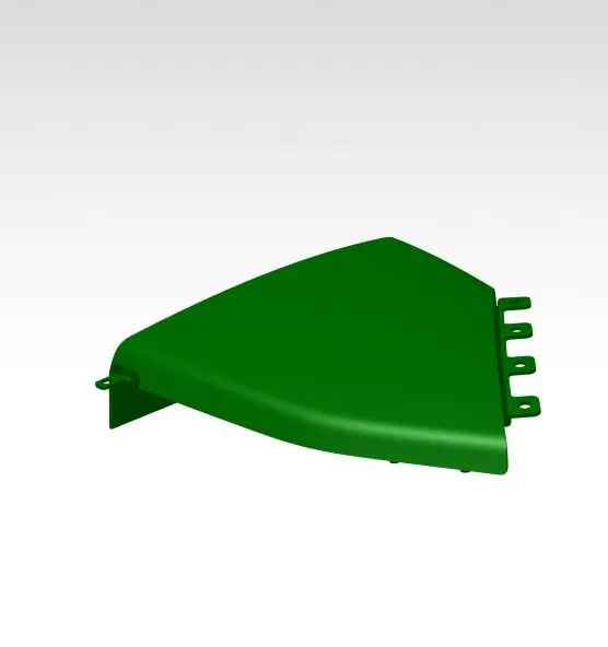
Creation of Tooling Axis:
- For creating tooling axis here in the given model Lower Substraite, used the Normal To Surface method.
- For creation of tooling axis, one of the surface is extracted and a point is inserted on the extracted surface
- Through the point the tooling axis is drawn.
Class A Surface with Tooling Axis:
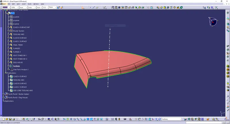
Draft Analysis of Class A Surface:
Checking the Draft Analysis for the Class A surface with respect to created Tooling Axis. To ensure the created Tooling Axis is in correct way.
Draft Analysis of Class A Surface with main tooling axis:
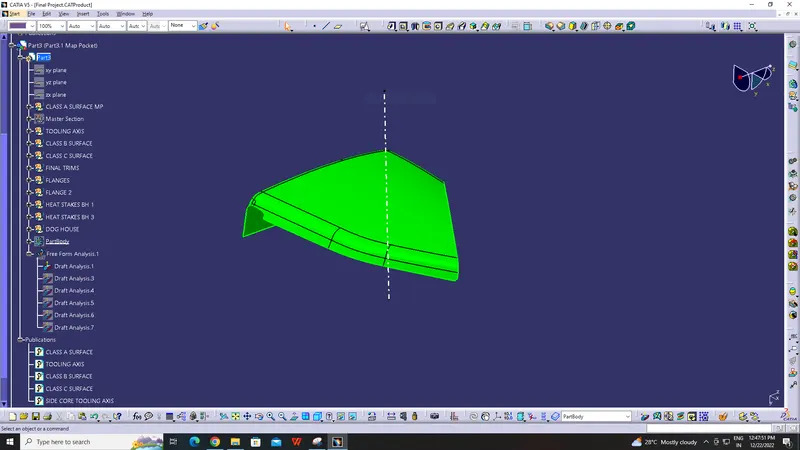
Creation of Class B Surface:
Here, the thickness given is = 2.5mm. So the given input Class A Surface is offseted to 2.5mm to obtain the Class B Surface.
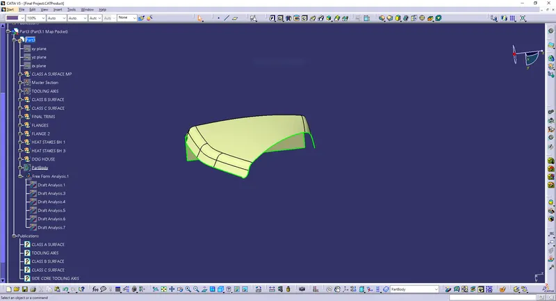
Creation of Class C Surface:
- Boundary of class A surface is extracted and then smoothcurved the boundaries if its required
- Also here Multi-Section Surface command is used to create the Class C Surface
- Both the sweep surface and multi-section surface are joined together to form as a single one.
- Then that boundary is swept perpendicular to the Class A Surface until it gets coincided with the offsetted class B surface.
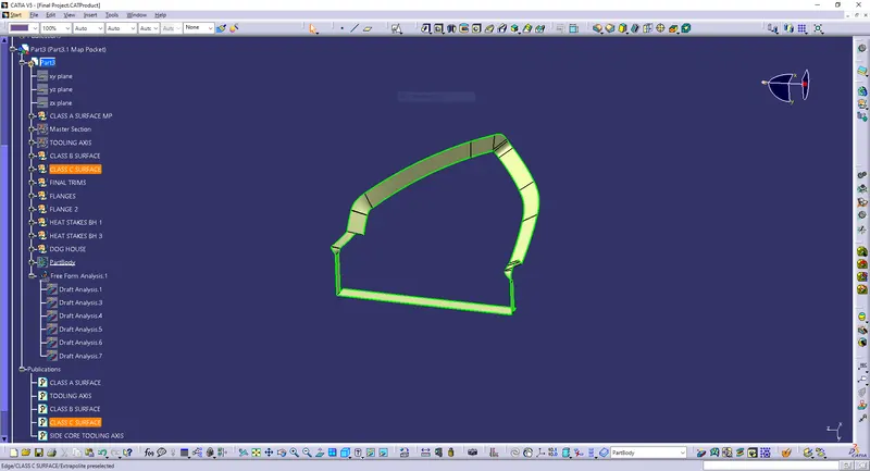
Enclosed Surface Creation:
Closed Body:
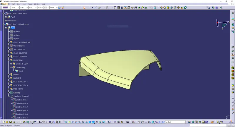
Attachment of Engineering Features Creation Using Master Section:
Flanges:
- These flanges will be build on the components for the fittment purpose with lower substrate.
- The hole at center will be guided along the heat stakes.
- Later top portion of the heat stake will be melted over it.
- The flange should rest on the supporting ribs on side .
Heat Stakes:
Heat Staking is a pulsed-heat process to join two or more parts out of which one at least is made of plastic.
- The process is to deform the plastic material using heat and force at a set process time.
- The bond is made by partially de-forming the plastic part in order to fix the other.
- Heat Staking makes it easy to bond metal to plastic and is commonly used in high volume/low cost applications such as automotive, IT and consumer appliances.
- Similar and dissimilar materials may be joined: metal to metal, plastic to plastic, metal to plastic
- Accurate control operating within a small process window
- Local heating resulting in no damage to surrounding materials
- Processing of glass-filled materials
- No mechanical vibration
- Many heat-stake shapes possible through custom designed tools.
Ribs attached to Heat Stakes
- The ribs provide economical stiffness and strength to the part without increasing the overall thickness of the part.
- The ribs are used as locating and arresting in the assembly as locators.
- Proper allignment in mating parts, slot and rib pair is long lasting other than screw pair which loosen up with time.
- Acting as stops or guide for mating the tilted headlamps.
- Rib designs includes: thickness, quantity, height , manufacturibility and location.
Dog House
- Dog house is the attachment feature which helps you to assemble things at certain heights and also resolve the plastic defects.
- There are plenty dog house design which can be used for assembly purpose but we will be using the one provided to ous by the resources.
- The master section or the enginnering drawing must be followed for creating the dog house.
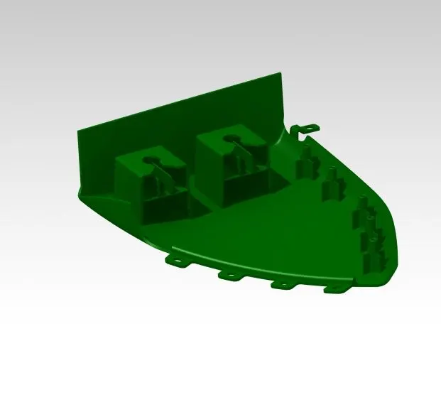
Solid Body with Attachment Feature:
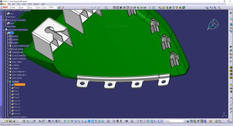
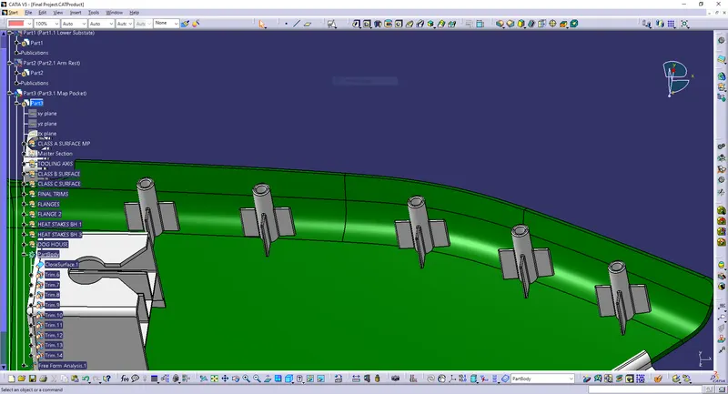
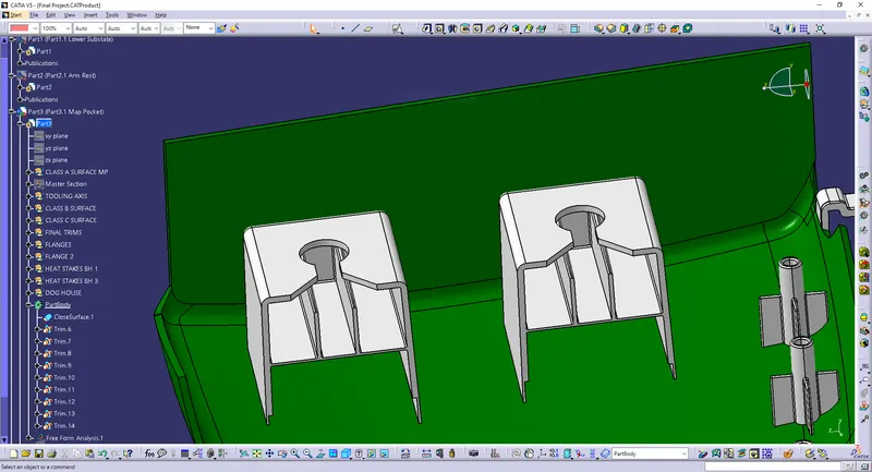
Final Model:
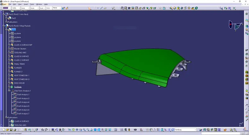
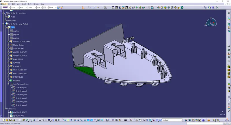
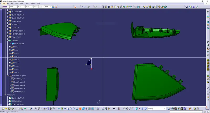
Draft Analysis:
Procedure:
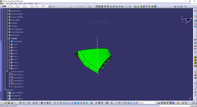
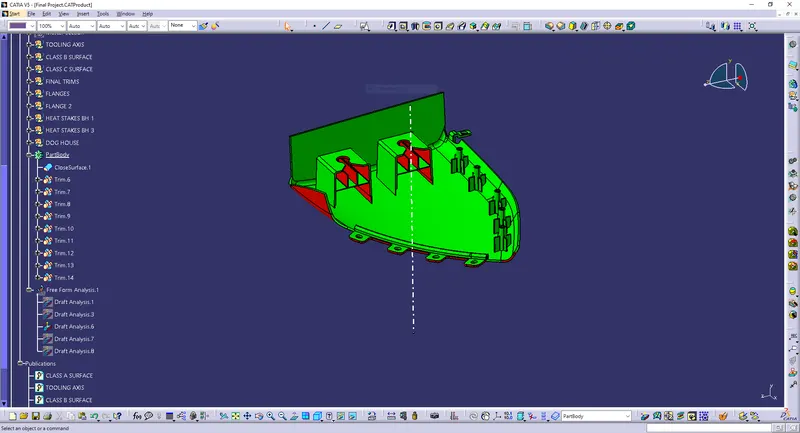
- Change the view mode to customize view parameters and give material as view mode.
- In the draft analysis toolbar, set the draft values and color (3 degree and above - green, 0 to 3 degree - blue, less than 0 - red).
- Drag and drop the axis system on the tooling axis and lock it.
- Perform draft analysis.
Draft Analysis of Solid Body:
Draft Analysis of Attachment Feature:
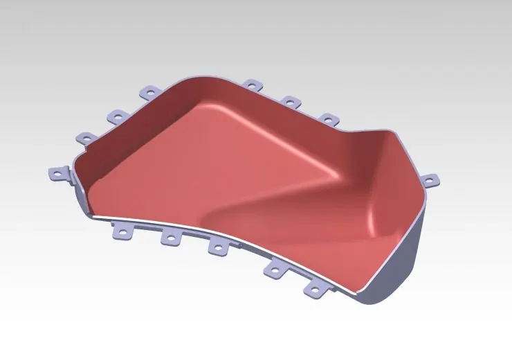
4. Map Pocket With Bottle Holder:
Creation of Tooling Axis:
- For creating tooling axis here in the given model Lower Substraite, used the Normal To Surface method.
- For creation of tooling axis, one of the surface is extracted and a point is inserted on the extracted surface
- Through the point the tooling axis is drawn.
Class A Surface with Tooling Axis:
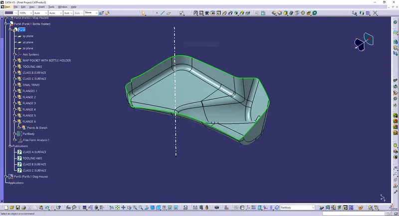
Draft Analysis of Class A Surface:
Checking the Draft Analysis for the Class A surface with respect to created Tooling Axis. To ensure the created Tooling Axis is in correct way.
Draft Analysis of Class A Surface with main tooling axis:
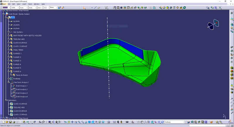
Creation of Class B Surface:
Here, the thickness given is = 2.5mm. So the given input Class A Surface is offseted to 2.5mm to obtain the Class B Surface.
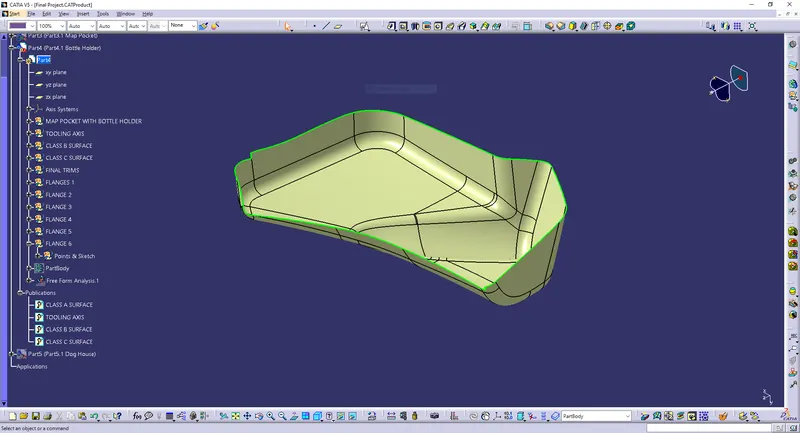
Creation of Class C Surface:
- Boundary of class A surface is extracted and then smoothcurved the boundaries if its required
- Also here Multi-Section Surface command is used to create the Class C Surface
- Both the sweep surface and multi-section surface are joined together to form as a single one.
- Then that boundary is swept perpendicular to the Class A Surface until it gets coincided with the offsetted class B surface.
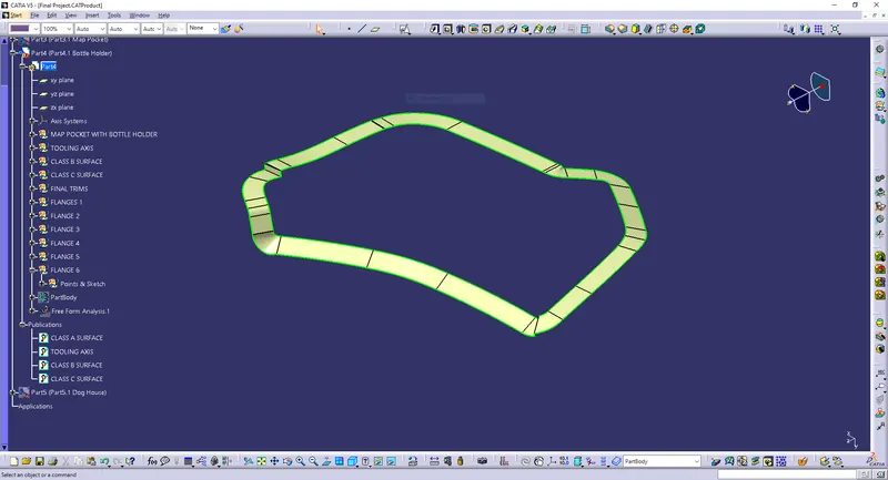
Enclosed Surface Creation:
Closed Body:
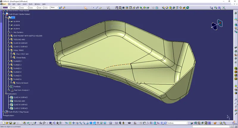
Attachment of Engineering Features Creation Using Master Section:
Flanges:
- These flanges will be build on the components for the fittment purpose with lower substrate.
- The hole at center will be guided along the heat stakes.
- Later top portion of the heat stake will be melted over it.
- The flange should rest on the supporting ribs on side.
Solid Body with Attachment Feature:
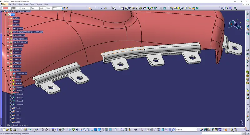
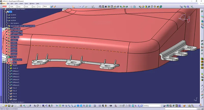
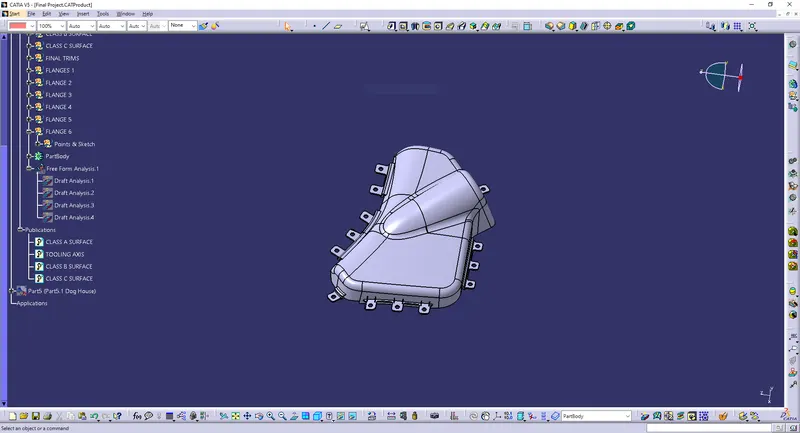
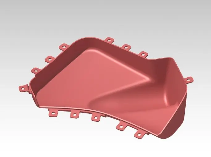
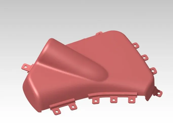
Final Model:
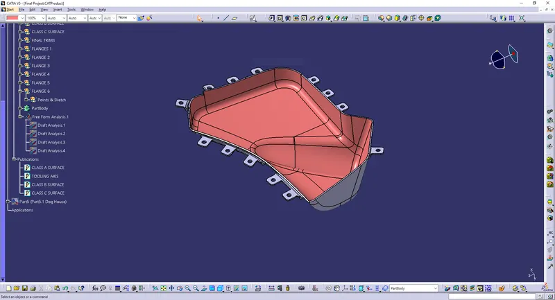
Draft Analysis:
Procedure:
- Change the view mode to customize view parameters and give material as view mode.
- In the draft analysis toolbar, set the draft values and color (3 degree and above - green, 0 to 3 degree - blue, less than 0 - red).
- Drag and drop the axis system on the tooling axis and lock it.
- Perform draft analysis.
Draft Analysis of Solid Body:
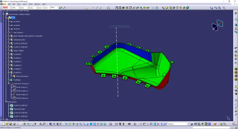
Draft Analysis of Attachment Feature:
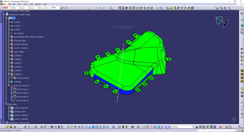
Final Result of Door Panel: