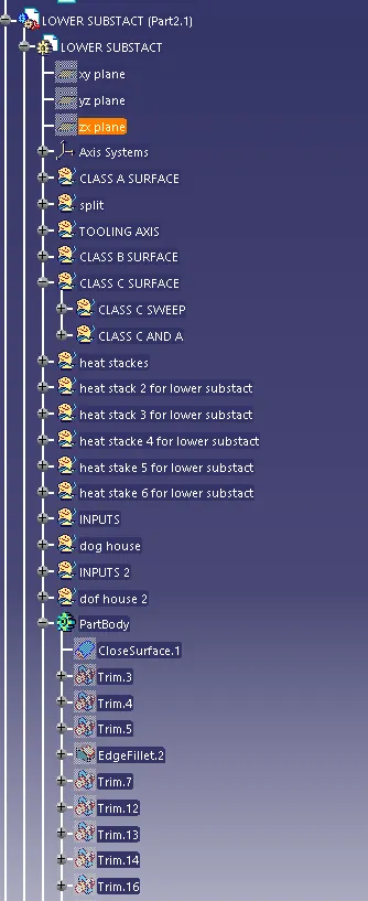
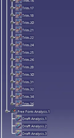
Week 11 - Final project
Development of Door Trim Panel
Aim : To create a CAD model of a side door trim panel from given class A surface .
Objective:
a) Creation of side door trim panle from given class A surface . Apply thickness to it and use attachment features .
b) Creation of flanges and heat stakes from given master sections .
c) Creation of dog house and various attachment features using industry standards .
d) Performing draft analysis and ensuring the features and surfaces clear it .
MATERIAL USED:
METARIAL SELECTION:
- ABS
- POLYPROPELENE
WHY THIS MATERIAL ARE USED:
- ABS has a low melting point which enable its easy use in the injection moulding process and 3D printing .It also has high tensile strength and is very resistance to physical impacts and chemical corrosion,which allow the finished plastic to withstand heavy use and adverse environmental condition.
- High dimensional stability (mechanically strong and stable over time).
- High surface brightness and excellent surface aspect.
Introduction :
The ten stages in automotive product life cycle developement are listed below .
1)Concept sketch
2) Styling class A
3)Feasilbility check
4)Concept validation
5)New product design
6)Product developement
7) Prototyping
8)Design validation
9)Pilot production
10)Mass production
From the above stages , it isin stage 5 that new product is developed and validated from class A surface . The objective is to design class B and class C surface from given class A surface and create a solid body from it using softwares like CATIA V5, solidworks or solidedge taking into consideration the draft analysis which makes the component suitable for production using injection molding process .
Given below is the procedure to create a new plastic component from given class A surface .
1) Creation of tooling axis
2) Creation of class b surface
3) Creation of class C surface
4) Creation of closed body
5) Draft Analysis .
Draft analysis is done to ensure that the designed part is manufacturable based on the draft conditions applied. It is done to ensure the proper ejection of the component from dies(for metals) or molds(for plastics). The basic idea is to ensure that the tooling axis has to be created in such a wat that it has no parallel surface profiles of the component so that the ejection of the components can be ensured . Tooling axis is the axis along which cavity and core are closed and opened .
The main components of interior door panel of a car consists of the following parts .
1) Arm rest
2) Map pocket (Consists of upper and lower part)
3) Upper substrate (Not given in the current model)
4) Lower substrate .
Step by step procedure
1) Creation of tooling axis
To create tooling axis , we must import the model into catia as a product .
File=>open=>browse=> MASTER SECTION DEVELOPEMENT.igs file .
GIVEN CLASS A SURFACE:
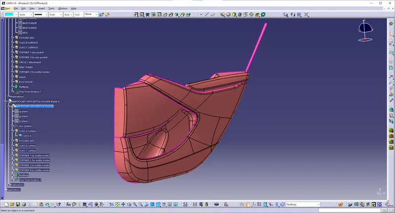
Rear side of the class A with master section :
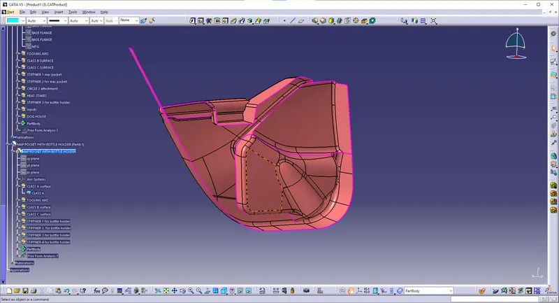
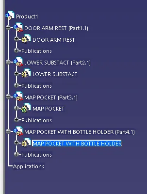
Create a product file and copy each component into different part files and name the accordingly .
Procedure to check for Draft analysis
1)Once the tooling axis is created , publish it and the component using Publication from tool option .
2)Insert Feature draft analysis option from insert tool bar
3) Change the view option to customize view parameters and click on material option under shading .
4) Now click on the axis option from Draft analysis tools , allign it with tooling axis and click on lock option to lock it .
5) Change draft angle value to 3 degree . Click on quick analysis mode to display feature according to given color scale . Check from all views to ensure the draft analysis is cleared .
6) Since the created tooling axis does not clear the draft analysis at the created axis , click on the lock axis button to unlock it . Now rotate the tooling axis by left clicking on the top round portion of the axis system . Rotate the axis till maximum clearance is obtained . Now right click on the axis and click lock current axis .
7) Create a line using the initial axis origin and this axis using point and direction (using compass direction) option . This is our required tooling axis .
8) Now if we check for draft analysis, we can observe that the ribbed area has not yet cleared draft analyisis. Hence we need to create a side core tooling axis . To do this , create a line using point and direction option with Y direction .
9) Repeat steps 1 to 5 to ensure the remaing portion which was not cleared using Tooling axis has been cleared using this axis .
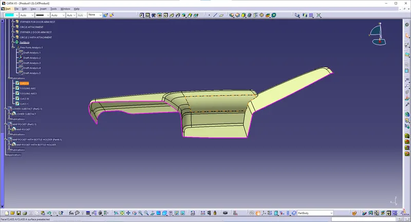
CLASS A SURFACE FOR DOOR ARM REST:
Class A surface is a surface made by the designer specially in automotive design which is the aesthetic part of a body and is given as an input to the plastic designer to work on it.
Creation Of Class A Surface
- Class A surface is obtained as the input.
- Join all the surfaces to obtain Class A surface if different surfaces are given as input and ensure no gap is present between any surfaces. Thus, Class A surface is obtained and publish it. Here, the provided surface is completely joined and can be taken as class A surface.
- For the file provided, there is a projection which is found out to be not the part of real class A surface, so that surface is splitted from main class A surface.
- Publish class A surface.

TOOLING AXIS FOR DOOR ARM REST:
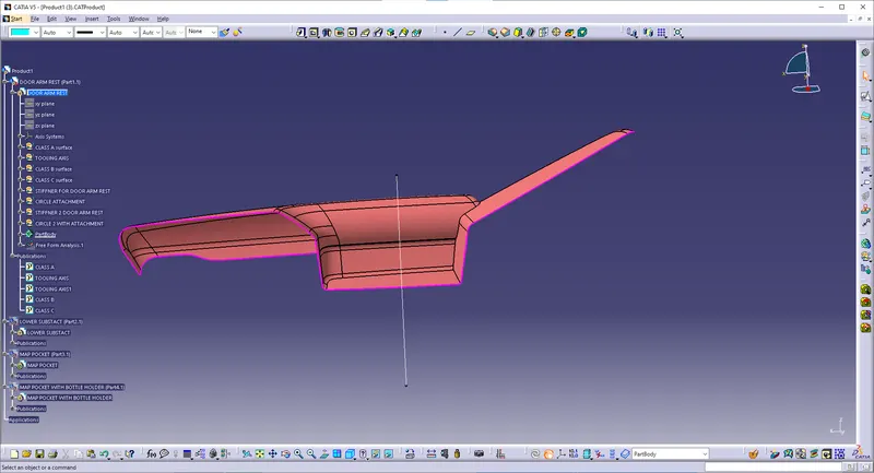
Tooling axis is the direction in which the core and cavity opens. If we are using proper tooling axis, we can avoid adding side cores thus the cost of manufacturing the component can be reduced.
It is defined as the direction in which the mould/core and cavity open. Selection of the direction of the tooling axis depends on the ease at which components can be easily ejected.
Generally tooling axis is decided from the natural axis of the design, that is, tooling axis is analysed with the x, y and z axis of the system. If the axis doesn’t clear the draft analysis, the next step is to look for the surface in which the drafting axis can be created in such a way that the axis is normal to the surface taken.
Creation Of Tooling Axis
- Tooling axis here created is by selecting one of the natural axes as it clears the draft.
- Here, tooling axis is created by extracting one of the surfaces for creating a point and a new axis is created at that point.
- So, a flat face is extracted and created a point at its centre. Axis is also created at that point.
- Now, line is created using line tool and giving line type as point-direction and selected the point and direction for creating tooling axis. Tooling axis is created along y direction.
- Publish Tooling axis.
side core tooling axis:

CLASS B SURFACE :
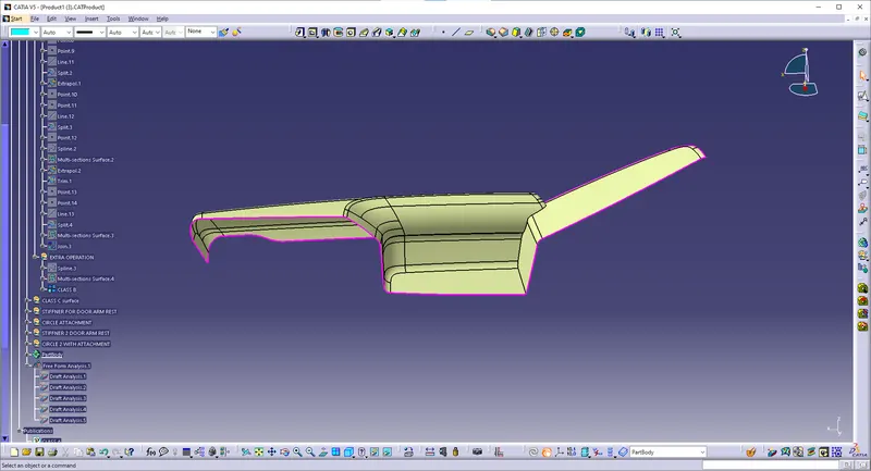
It is a surface which comes below the class A surface with a particular thickness. This surface contains engineering features of a model.
Creation Of Class B Surface
- Now, Class B surface has to be created. For this, multiple extract is used to extract surface in a single operation. Surfaces obtained are the offsetted for 2.5mm.
- Small filleted portions are avoided from extract and other surfaces are extracted. Small fillets are avoided as when they are offsetted to 2.5mm, fillets cannot be automatically formed in CATIA.
- Similarly, other surfaces are extracted avoiding the fillets and offsetted, extrapolated and trimmed with the main surface to get proper B class surface.
- Fillets are measured from the Class A surfaces and appropriate fillets are provided for Class B surface by adding or subtracting the thickness of the component to obtain correct thickness everywhere.
- Publish class B surface.
class c surfce:
It is the surface which joins class A with class b surface.
Creation Of Class C Surface
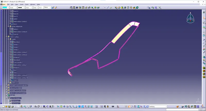
- Now class C surface has to be created and it is created from the boundaries obtained from the Class A surface. This boundary is provided as the input curve for sweep command. Using sweep command, class C surface is created.
- Appropriate sweep is the provided considering the flash and considering manufacturing procedures. Surfaces are extrapolated if necessary.
- Publish class C surface.
class A&C join:
final trim :
Creation Of Closed Surface
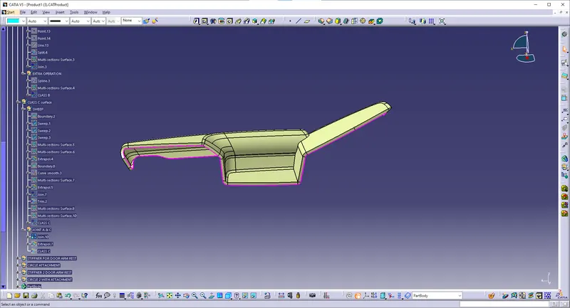
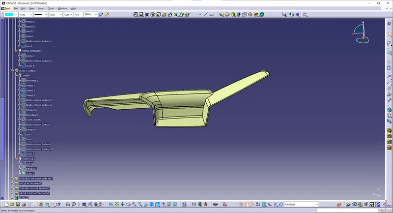
- Now Class A surface and Class C surface is joined.(A&C JOIN)
- Now Class B surface is also trimmed with the obtained surface to get the closed surface. (FINAL TRIM)
DRAFT ANALYSIS FOR DOOR ARM REST:
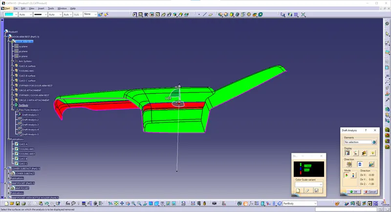
From draft analysis, we can verify draft angles, examine the angle changes within a face, as well as locate parting lines, injection and ejection surfaces in parts.
It is an important feature in Catia which helps the user to analyse the draft on various surfaces. The draft analysis toolbar provides two modes for analysis of the draft, first is the quick analysis which basically has three colours (green, red, and blue) for analysing on the other hand other option is the full analysis mode which enables a few more details into the draft and is used in the complex components.
class a surface
side core draft analysis:
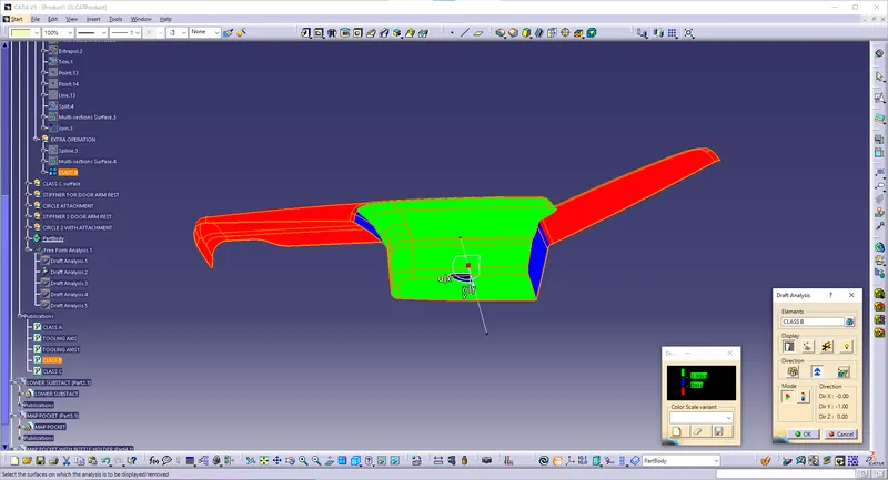
draft analysis for final trim:
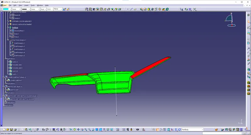
draft analysis for side core final trim:
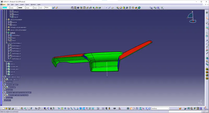
OVERALL DRAFT ANALYSIS WITH FLANGE :
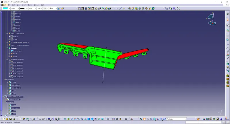
SIDE CORE DRAFT ANALYSIS WITH FLANGE:
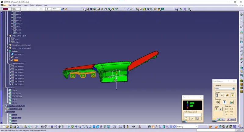
CLOSED SURFACE ARM REST:
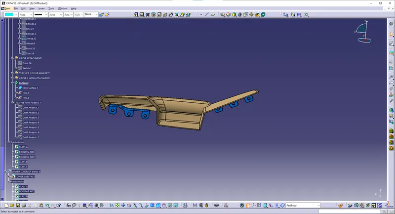
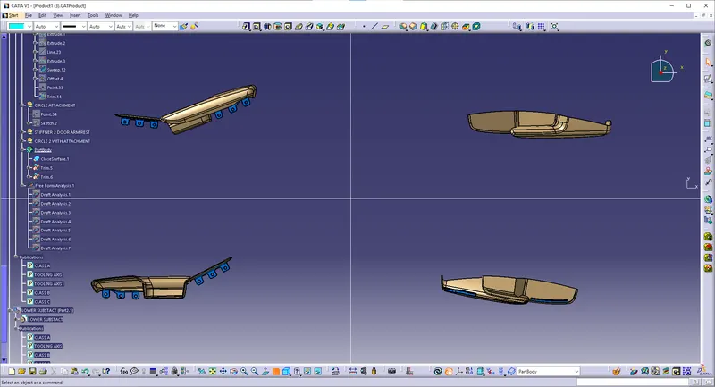
MAC POCKET WITH BOTTLE HOLDER:
CLASS A SURFACE
Class A surface is a surface made by the designer specially in automotive design which is the aesthetic part of a body and is given as an input to the plastic designer to work on it.
Creation Of Class A Surface
- Class A surface is obtained as the input.
- Join all the surfaces to obtain Class A surface if different surfaces are given as input and ensure no gap is present between any surfaces. Thus, Class A surface is obtained and publish it. Here, the provided surface is completely joined and can be taken as class A surface.
- For the file provided, there is a projection which is found out to be not the part of real class A surface, so that surface is splitted from main class A surface.
- Publish class A surface.
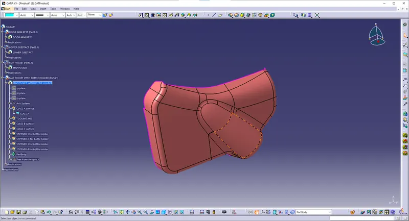
TOOLING AXIS:
Tooling axis is the direction in which the core and cavity opens. If we are using proper tooling axis, we can avoid adding side cores thus the cost of manufacturing the component can be reduced.
It is defined as the direction in which the mould/core and cavity open. Selection of the direction of the tooling axis depends on the ease at which components can be easily ejected.
Generally tooling axis is decided from the natural axis of the design, that is, tooling axis is analysed with the x, y and z axis of the system. If the axis doesn’t clear the draft analysis, the next step is to look for the surface in which the drafting axis can be created in such a way that the axis is normal to the surface taken.
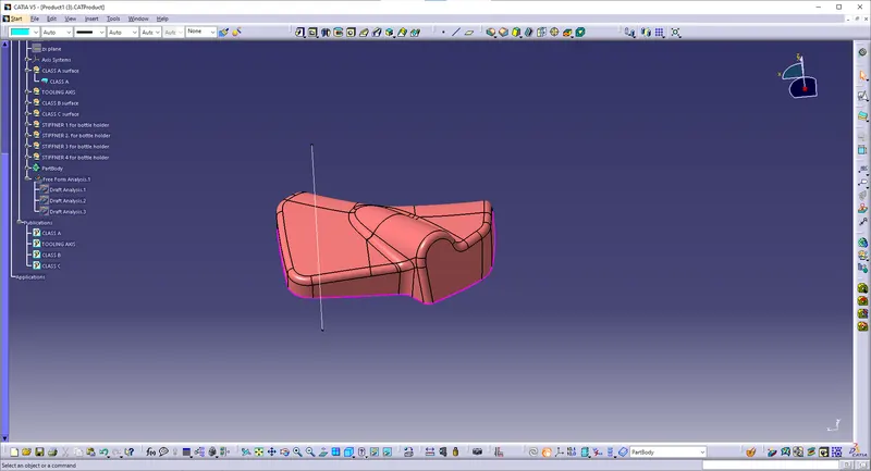
CLASS B SURFACE:
It is a surface which comes below the class A surface with a particular thickness. This surface contains engineering features of a model
Creation Of Class B Surface
- Now, Class B surface has to be created. For this, multiple extract is used to extract surface in a single operation. Surfaces obtained are the offsetted for 2.5mm.
- Small filleted portions are avoided from extract and other surfaces are extracted. Small fillets are avoided as when they are offsetted to 2.5mm, fillets cannot be automatically formed in CATIA.
- Similarly, other surfaces are extracted avoiding the fillets and offsetted, extrapolated and trimmed with the main surface to get proper B class surface.
- Fillets are measured from the Class A surfaces and appropriate fillets are provided for Class B surface by adding or subtracting the thickness of the component to obtain correct thickness everywhere.
- Publish class B surface.
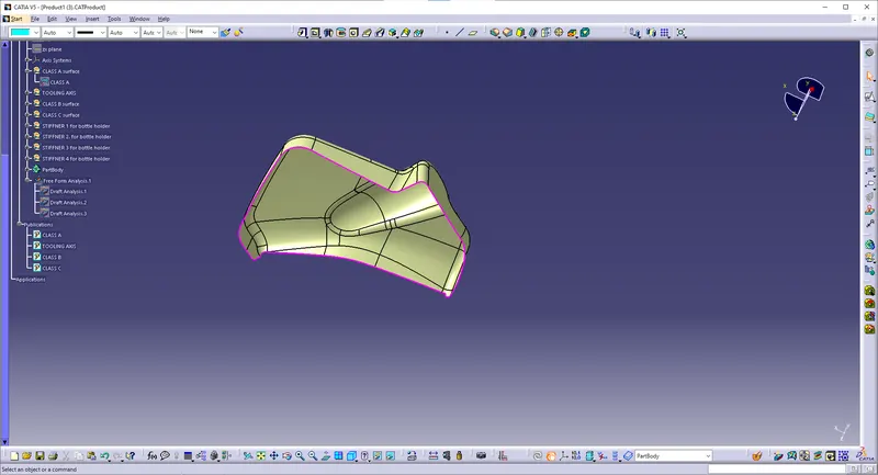
CLASS C SURFRACE:
It is the surface which joins class A with class b surface.
Creation Of Class C Surface
- Now class C surface has to be created and it is created from the boundaries obtained from the Class A surface. This boundary is provided as the input curve for sweep command. Using sweep command, class C surface is created.
- Appropriate sweep is the provided considering the flash and considering manufacturing procedures. Surfaces are extrapolated if necessary.
- Publish class C surface.
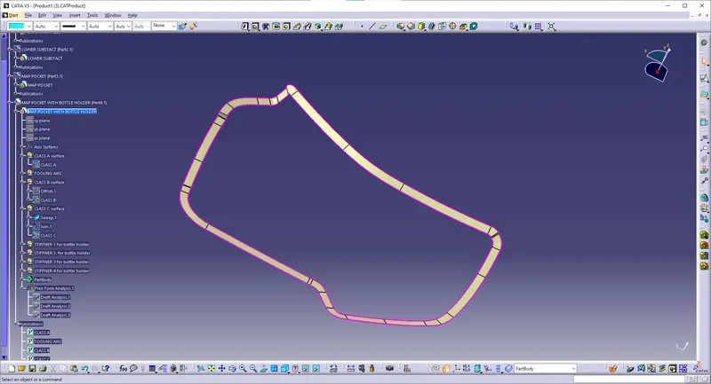
CLASS A&C JOIN:
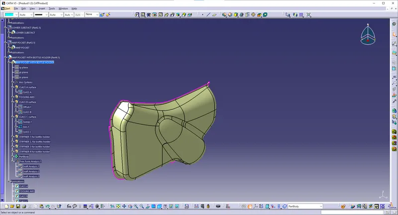
FINAL TRIM:
Creation Of Closed Surface
- Now Class A surface and Class C surface is joined.(A&C JOIN)
- Now Class B surface is also trimmed with the obtained surface to get the closed surface. (FINAL TRIM)
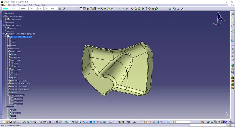
DRAFT ANALYSIS :
From draft analysis, we can verify draft angles, examine the angle changes within a face, as well as locate parting lines, injection and ejection surfaces in parts.
It is an important feature in Catia which helps the user to analyse the draft on various surfaces. The draft analysis toolbar provides two modes for analysis of the draft, first is the quick analysis which basically has three colours (green, red, and blue) for analysing on the other hand other option is the full analysis mode which enables a few more details into the draft and is used in the complex components.
CLASS A SURFACE:
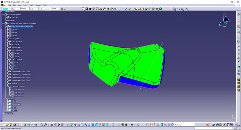
FINAL TRIM :
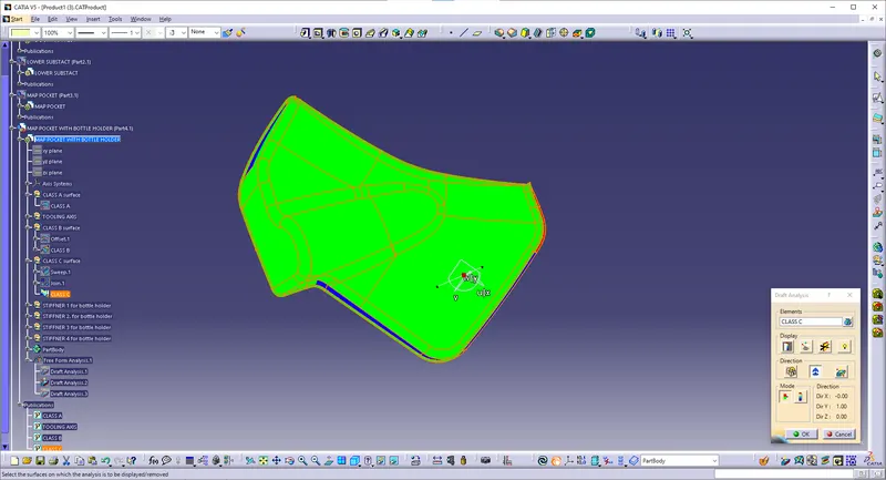
CLOSED SURFACE FOR BOTTLE HOLDER:
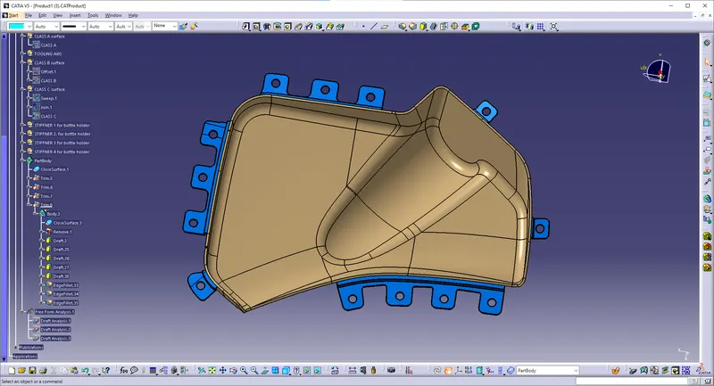
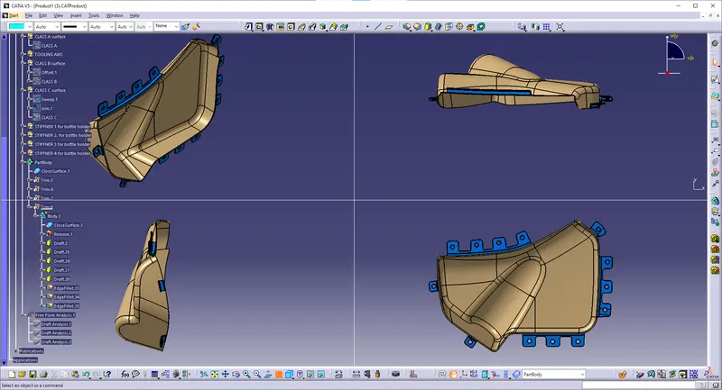
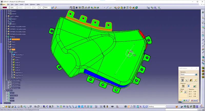
MAP POCKET:
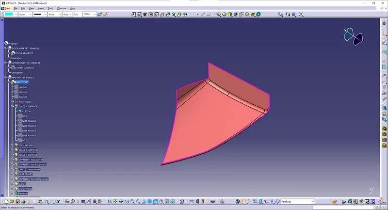
CLASS A SURFACE
Class A surface is a surface made by the designer specially in automotive design which is the aesthetic part of a body and is given as an input to the plastic designer to work on it.
Creation Of Class A Surface
- Class A surface is obtained as the input.
- Join all the surfaces to obtain Class A surface if different surfaces are given as input and ensure no gap is present between any surfaces. Thus, Class A surface is obtained and publish it. Here, the provided surface is completely joined and can be taken as class A surface.
- For the file provided, there is a projection which is found out to be not the part of real class A surface, so that surface is splitted from main class A surface.
- Publish class A surface.
TOOLING AXIS :
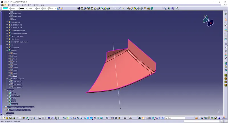
Tooling axis is the direction in which the core and cavity opens. If we are using proper tooling axis, we can avoid adding side cores thus the cost of manufacturing the component can be reduced.
It is defined as the direction in which the mould/core and cavity open. Selection of the direction of the tooling axis depends on the ease at which components can be easily ejected.
Generally tooling axis is decided from the natural axis of the design, that is, tooling axis is analysed with the x, y and z axis of the system. If the axis doesn’t clear the draft analysis, the next step is to look for the surface in which the drafting axis can be created in such a way that the axis is normal to the surface taken.
CLASS B SURFACE:
It is a surface which comes below the class A surface with a particular thickness. This surface contains engineering features of a model
Creation Of Class B Surface
- Now, Class B surface has to be created. For this, multiple extract is used to extract surface in a single operation. Surfaces obtained are the offsetted for 2.5mm.
- Small filleted portions are avoided from extract and other surfaces are extracted. Small fillets are avoided as when they are offsetted to 2.5mm, fillets cannot be automatically formed in CATIA.
- Similarly, other surfaces are extracted avoiding the fillets and offsetted, extrapolated and trimmed with the main surface to get proper B class surface.
- Fillets are measured from the Class A surfaces and appropriate fillets are provided for Class B surface by adding or subtracting the thickness of the component to obtain correct thickness everywhere.
- Publish class B surface.
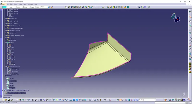
CLASS C SURFACE:
It is the surface which joins class A with class b surface.
Creation Of Class C Surface
- Now class C surface has to be created and it is created from the boundaries obtained from the Class A surface. This boundary is provided as the input curve for sweep command. Using sweep command, class C surface is created.
- Appropriate sweep is the provided considering the flash and considering manufacturing procedures. Surfaces are extrapolated if necessary.
- Publish class C surface.
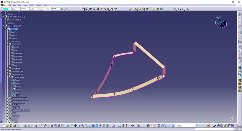
CLASS A&C JOIN:
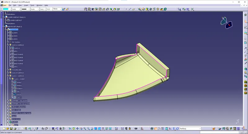
FINAL TRIM:
Creation Of Closed Surface
- Now Class A surface and Class C surface is joined.(A&C JOIN)
- Now Class B surface is also trimmed with the obtained surface to get the closed surface. (FINAL TRIM)
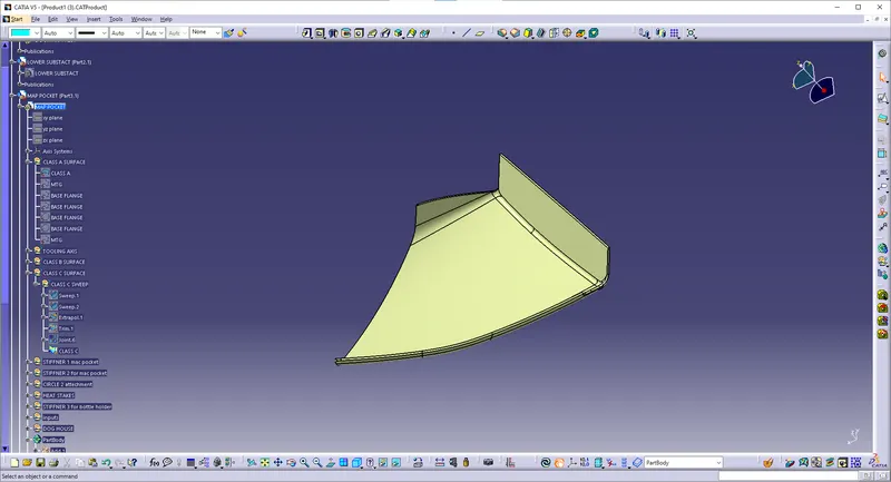
DRAFT ANALYSIS
DRAFT ANALYSIS :
From draft analysis, we can verify draft angles, examine the angle changes within a face, as well as locate parting lines, injection and ejection surfaces in parts.
It is an important feature in Catia which helps the user to analyse the draft on various surfaces. The draft analysis toolbar provides two modes for analysis of the draft, first is the quick analysis which basically has three colours (green, red, and blue) for analysing on the other hand other option is the full analysis mode which enables a few more details into the draft and is used in the complex components.
CLASS A SURFACE:
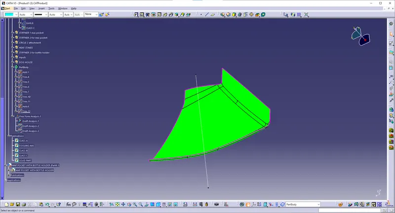
DRAFT ANALYSIS FOR FINAL TRIM:
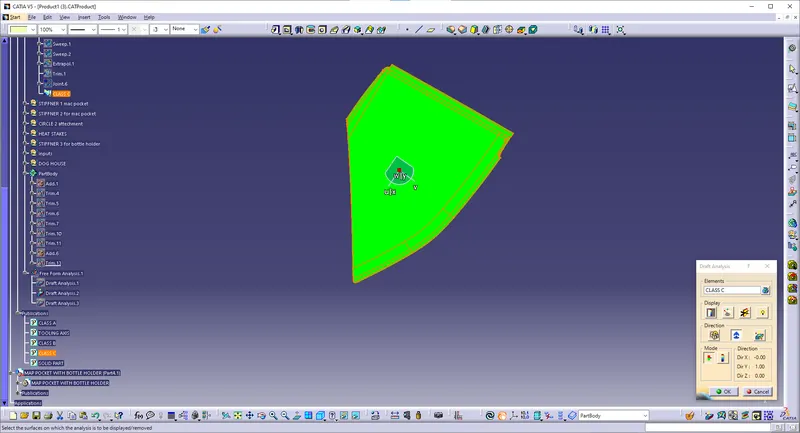
DRAFT ANALYSIS FOR MAP POCKET WITH DOG HOUSE AND FLANGE:
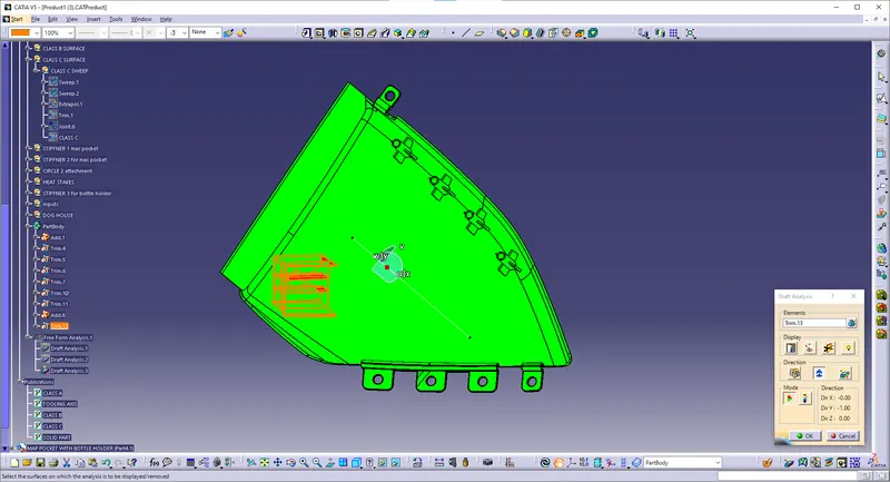
CLOSED SURFACE:
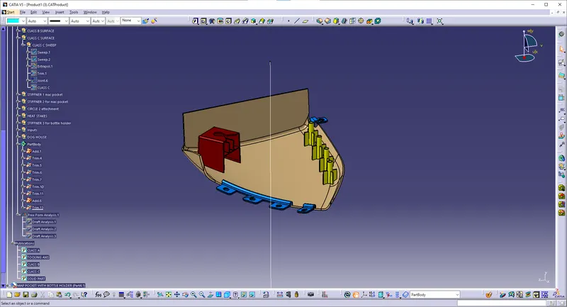
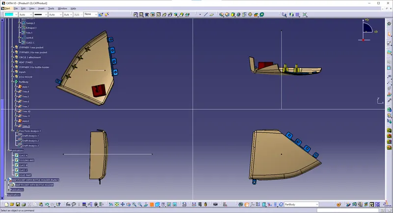
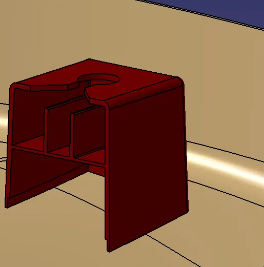
DOG HOUSE Creation
- Dog houses are designed to avoid SINK MARK created on the CLASS-A surface by screw bosses and to solve the length issues when giving screw bosses which need to be assembled to other components.
- It is also useful when perpendicular screw bosses are required on the part to the tooling direction.
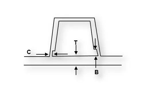
- C thickness should be 40% of the main wall thickness T
- Minimum width of the dog house is 12 mm.
- Height of B should be 3-6 mm
- Minimum draft for the do house is 1.5 degree to die draw.
- Lifter - Internal cutter (cutout)
- slider- outernal cutter (cutout)
- 60mm max height of doghouse [3.0-6.0]
- draft angles as 3degree or less than 3degree.we can use 1.5degree as a nominal degree of outer face of dof house
- inner draft angle of dog house should be 0.5degree
sink marks between 3-6mm height
- Doghouse are created by following the design rules.
- For this, a sketch is created and a rib is drawn.
- It is the padded by inserting a new body.
- Drafts are given for the surfaces as per design rules.
- For coring, surface is offsetted and it is split from the main surface.
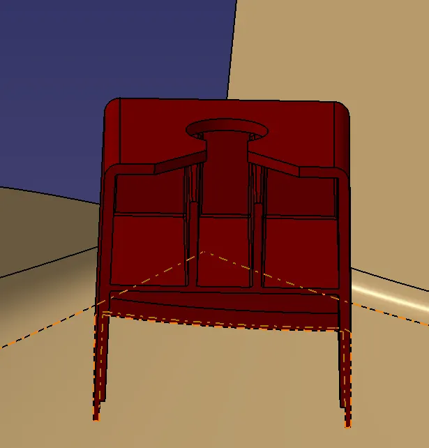
DRAFT ANALYSIS FOR DOG HOUSE:
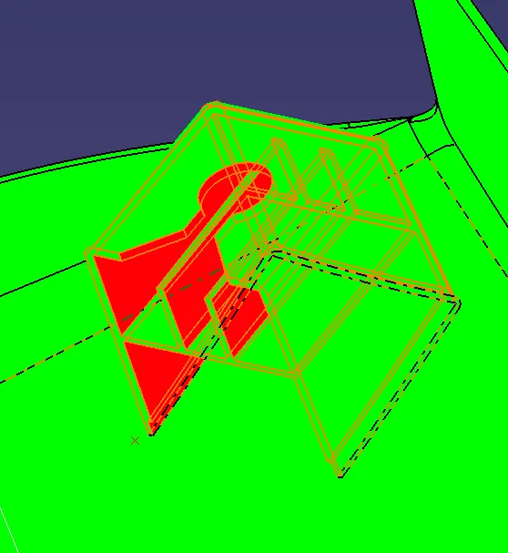
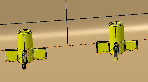
HEAT STAKE:
Creation Of Heat Stakes
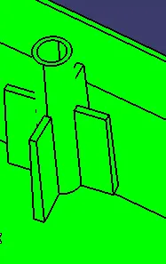
- Sketch for heat stakes is drawn and it is padded.
- Proper drafts are given for the clearing of the surfaces.
- Fillets are also provided.
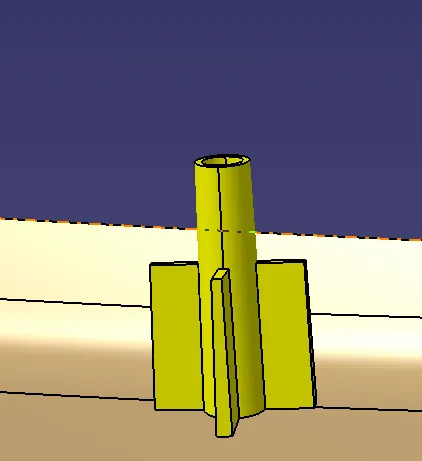
DRAFT ANALYSIS FOR HEAT STAKE:
LOWER SUBSTACT:
CLASS A SURFACE:
Class A surface is a surface made by the designer specially in automotive design which is the aesthetic part of a body and is given as an input to the plastic designer to work on it.
Creation Of Class A Surface
- Class A surface is obtained as the input.
- Join all the surfaces to obtain Class A surface if different surfaces are given as input and ensure no gap is present between any surfaces. Thus, Class A surface is obtained and publish it. Here, the provided surface is completely joined and can be taken as class A surface.
- For the file provided, there is a projection which is found out to be not the part of real class A surface, so that surface is splitted from main class A surface.
- Publish class A surface.
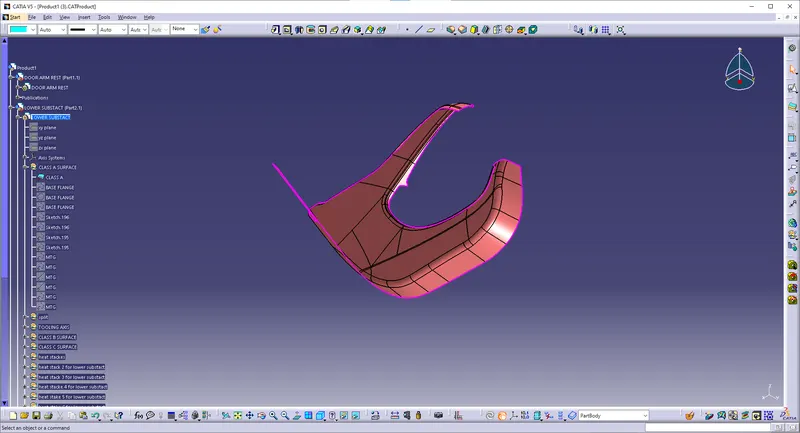
TOOLING AXIS:
Tooling axis is the direction in which the core and cavity opens. If we are using proper tooling axis, we can avoid adding side cores thus the cost of manufacturing the component can be reduced.
It is defined as the direction in which the mould/core and cavity open. Selection of the direction of the tooling axis depends on the ease at which components can be easily ejected.
Generally tooling axis is decided from the natural axis of the design, that is, tooling axis is analysed with the x, y and z axis of the system. If the axis doesn’t clear the draft analysis, the next step is to look for the surface in which the drafting axis can be created in such a way that the axis is normal to the surface taken.
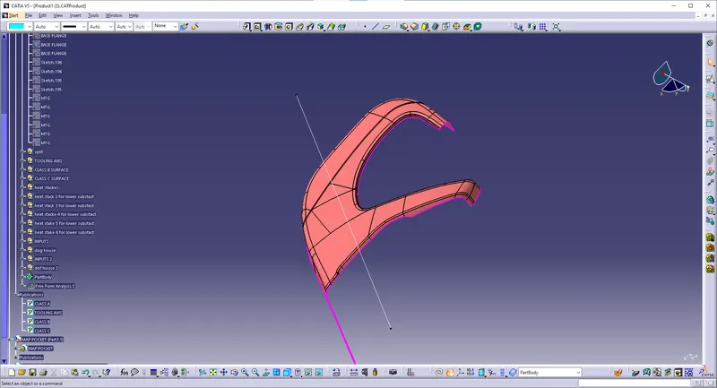
CLASS B SURFACE:
It is a surface which comes below the class A surface with a particular thickness. This surface contains engineering features of a model
Creation Of Class B Surface
- Now, Class B surface has to be created. For this, multiple extract is used to extract surface in a single operation. Surfaces obtained are the offsetted for 2.5mm.
- Small filleted portions are avoided from extract and other surfaces are extracted. Small fillets are avoided as when they are offsetted to 2.5mm, fillets cannot be automatically formed in CATIA.
- Similarly, other surfaces are extracted avoiding the fillets and offsetted, extrapolated and trimmed with the main surface to get proper B class surface.
- Fillets are measured from the Class A surfaces and appropriate fillets are provided for Class B surface by adding or subtracting the thickness of the component to obtain correct thickness everywhere.
- Publish class B surface.
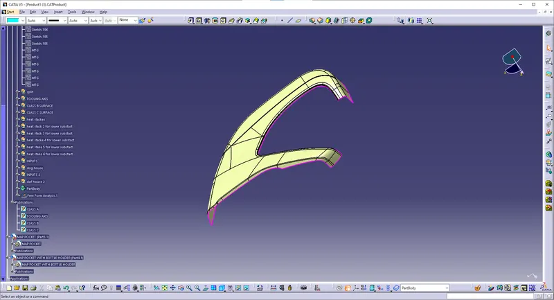
CLASS C SURFACE:
It is the surface which joins class A with class b surface.
Creation Of Class C Surface
- Now class C surface has to be created and it is created from the boundaries obtained from the Class A surface. This boundary is provided as the input curve for sweep command. Using sweep command, class C surface is created.
- Appropriate sweep is the provided considering the flash and considering manufacturing procedures. Surfaces are extrapolated if necessary.
- Publish class C surface.
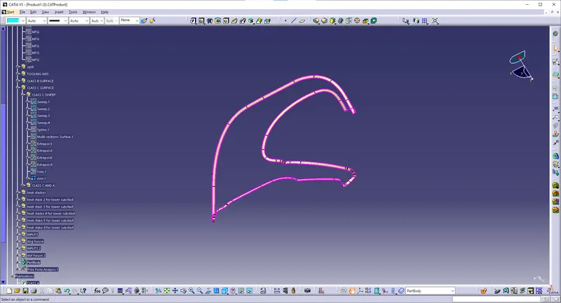
CLASS A&C JOIN:
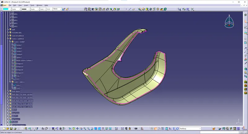
FINAL TRIM:
Creation Of Closed Surface
- Now Class A surface and Class C surface is joined.(A&C JOIN)
- Now Class B surface is also trimmed with the obtained surface to get the closed surface. (FINAL TRIM)
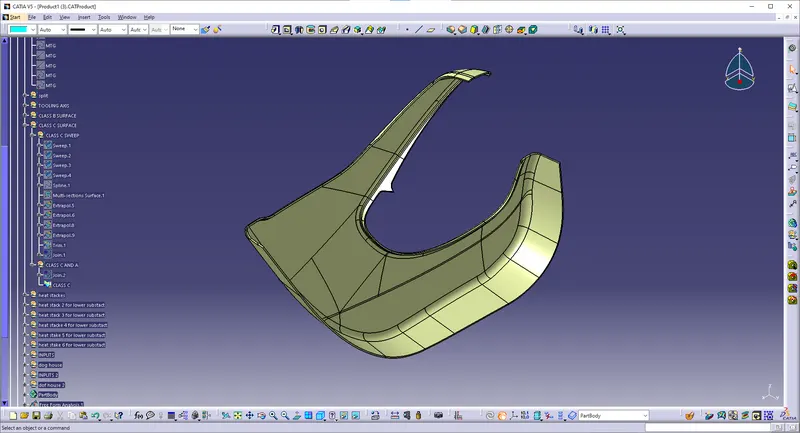
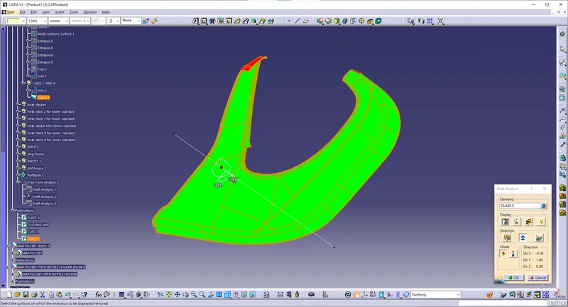
DRAFT ANALYSIS :
DRAFT ANALYSIS :
From draft analysis, we can verify draft angles, examine the angle changes within a face, as well as locate parting lines, injection and ejection surfaces in parts.
It is an important feature in Catia which helps the user to analyse the draft on various surfaces. The draft analysis toolbar provides two modes for analysis of the draft, first is the quick analysis which basically has three colours (green, red, and blue) for analysing on the other hand other option is the full analysis mode which enables a few more details into the draft and is used in the complex components.
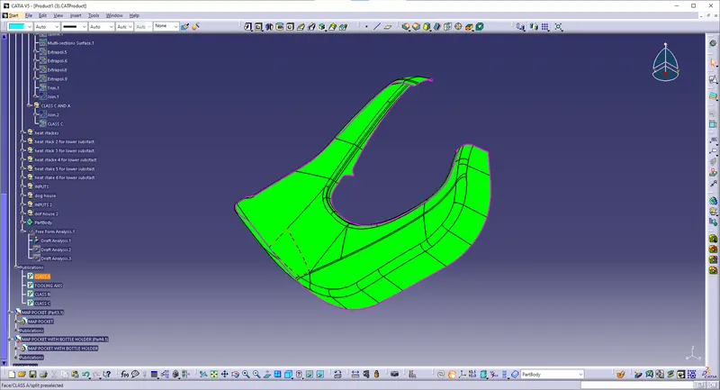
CLASS A SURFACE:
FINAL TRIM :
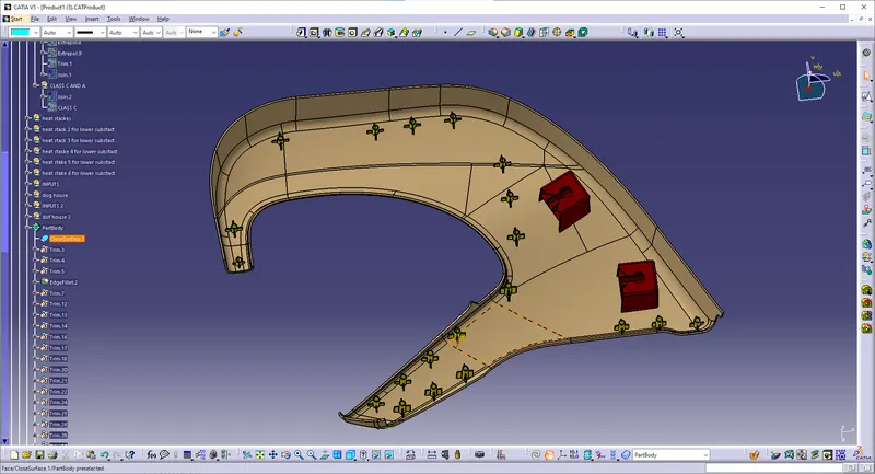
CLOSED SURFACE FOR LOWER SUBSTACTE :
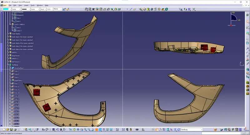
DRAFT ANALYSIS FOR OVERALL :
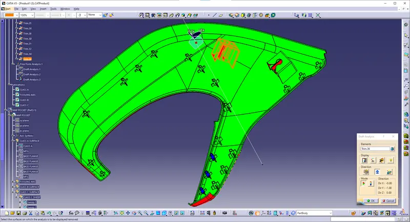
DRAFT ANALYSIS FOR HEAT STAKE
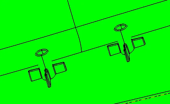
HEAT STAKE
DRAFT ANALYSIS FOR DOG HOUSE
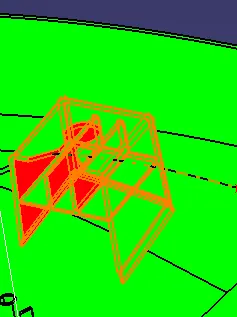
DOG HOUSE
FINAL BODY OF DOOR TRIM
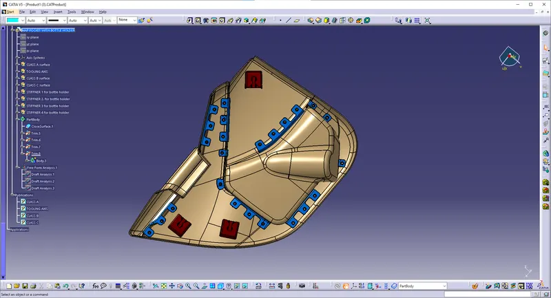

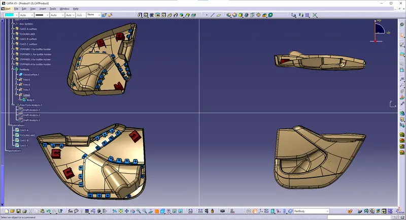
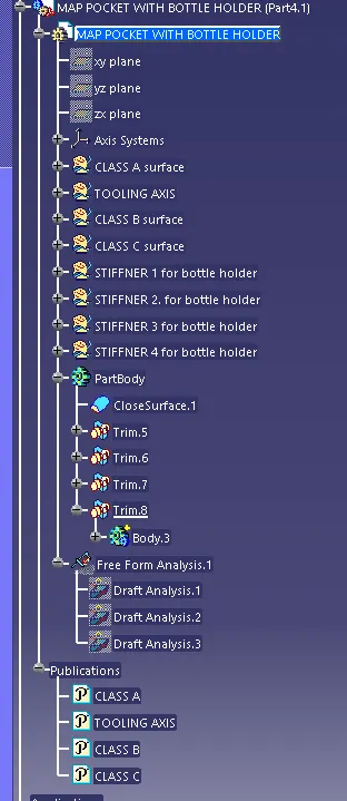
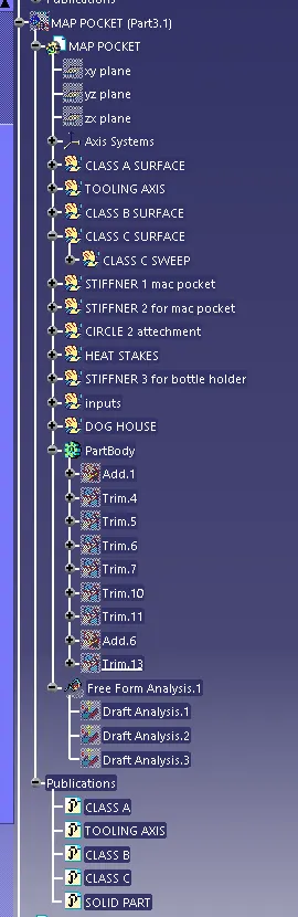
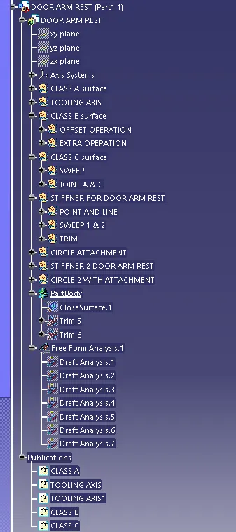
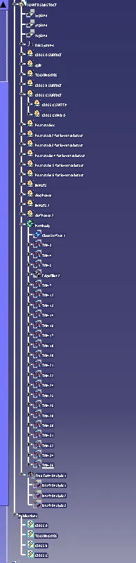
FAMILY TREE: