Week 11 - Final project
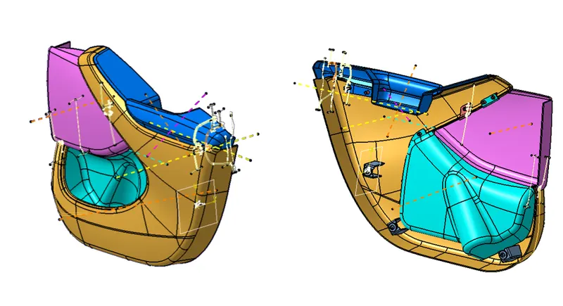
FINAL PROJECT - CAR DOOR TRIM DESIGN WITH GIVEN MASTER SECTION
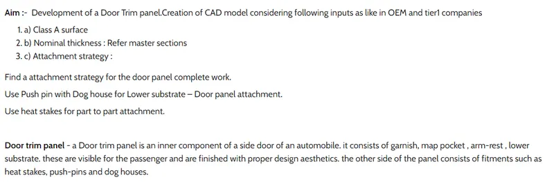
What is master section:
Master sections are the guides for design requirements which decide the component packaging after technical (Styling, Concept or Class-A) surfaces.
Concept & Feasibility
•Concept design / Design support and feasibility study
•Concept surface description
•Generate master sections and component packaging
•Technical surface description (A class)
•Deciding part configuration / split lines
•Gap & Flush requirement
•Feasibility study & simulations
•Assembly sequence & develop process diagram & spot plan drawings
•Preliminary weight analysis and bill of material
Package analysis
•Interior, exterior, engine, underbody, and luggage compartments
•Engine and passenger compartments
•Closures
Detail Design
•Modeling & drafting of vehicle components
•Sub assemblies & assemblies: Body in white, closures
•Tolerance analysis
Facelifts and Variants
•Minor freshening: rub rails, door trims, steering wheels, roof carriers, and decorative trims
•Moderate facelifts: bumpers, spoilers, grilles, steering wheels, door trims
•Mid-life facelifts: changes in bumpers, lamps, instrument panels & consoles, spoilers, grilles, steering wheels, door trims, new engine, RVMs, BIW changes to suit trim changes
•Major Facelifts: carryover platform
•Variants: from base hatch back platform to sedan and station wagon with or without W/B increase
Engineering Documentation
•Bill of Material generation and controlling
•Material specifications
•Chain of Dimension, Gap and Flush study and GD&T on drawings
•Design Failure Mode Effective Analysis (DFMEA)
•Product specifications, Design Validation Plan (DVP)
•Fastener selection
3D-engineering, 2D-drawings releases
•Body contour development
•Design according to tool, manufacturing or process requirements
•FMEAs
•Data management and Releasing
Geometrical Integration / Digital Mock Up (DMU):
•Package
•Collisions-check
•Design studies
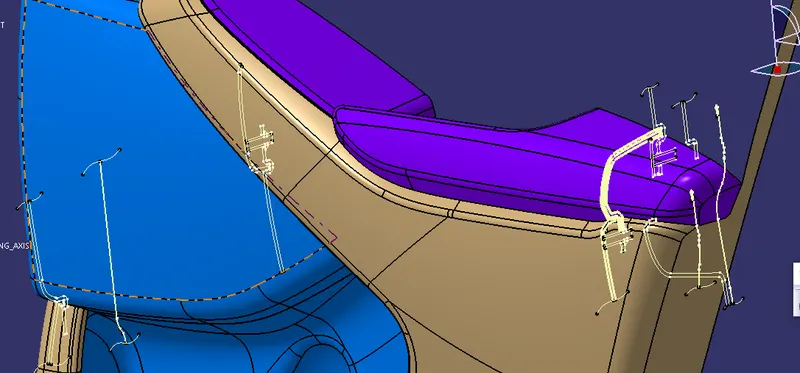
Tooling Axis:
- It is the direction in which the component will be ejecting after the molding process is completed.
- The direction of tooling axis should clear the maximum portion of the part.
- It should be selected in such way that number of side cores will be minimum as it will add more cost to the process.
Why Draft angle is important:
However, they are a required feature. A functional part for injection molding has to have drafts facing both cavity and core sides to reduce the risk of damage to the parts and ensure ejection. As the molten plastic flows into the closed die and fills the cavity, the material shrinks inside the mold upon cooling and as a result grips the core. Draft angles should be at least 3° to facilitate the part ejection.
- Reduces the chance of damage to the part due to friction during release.
- Reduces wear and tear and chances of damage to the mold.
- Ensures a uniform, smooth, unscratched finish when required.
- Ensures the integrity and uniformity of other surface finishes and textures.
- Reduces overall cooling time by lessening or eliminating the need for unconventional ejection setups.
Workbench and tools used
Generative shape design
- Extract
- Extrapolate
- Join
- Trim
- Offset
- Boundary
- Edge fillet
- Intersection
- Sweep
- Close surface
- Feature Draft Analysis
INPUT DATA
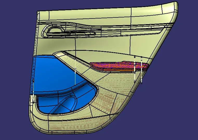
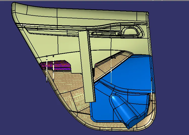
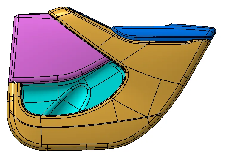
Class A surface,
After importing the class ‘A’ surface, we need to check the connectivity between the surface with merging distance 0.003 mm.
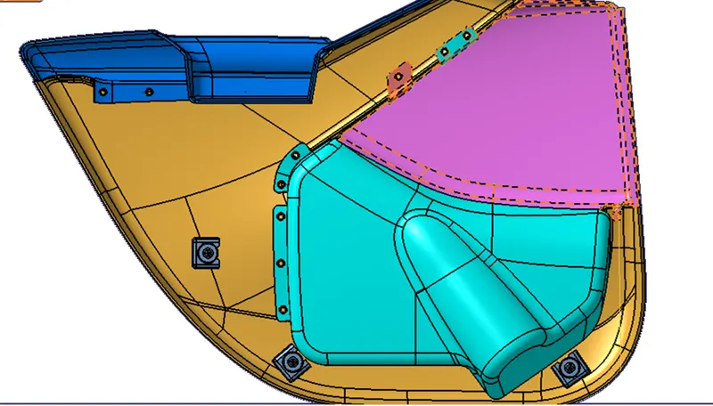
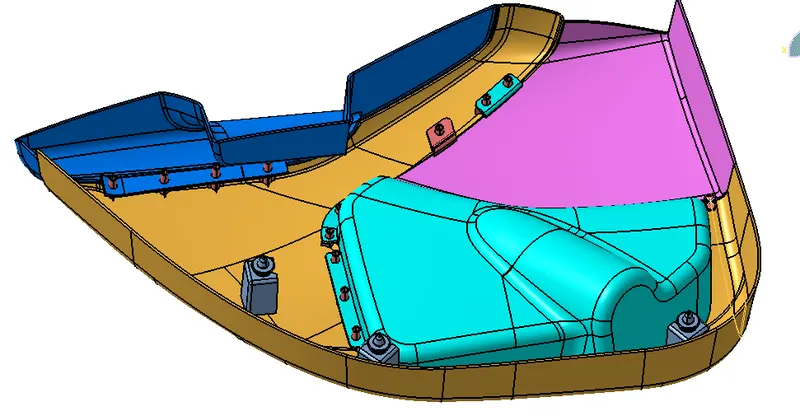
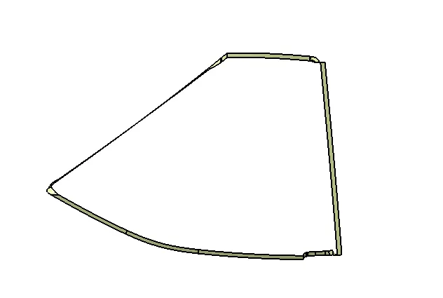
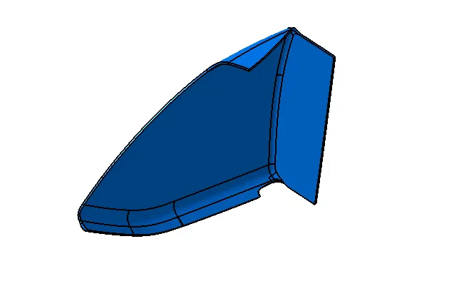
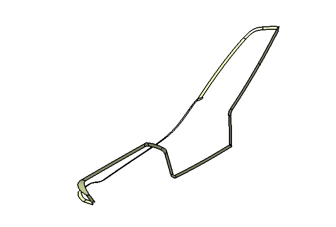
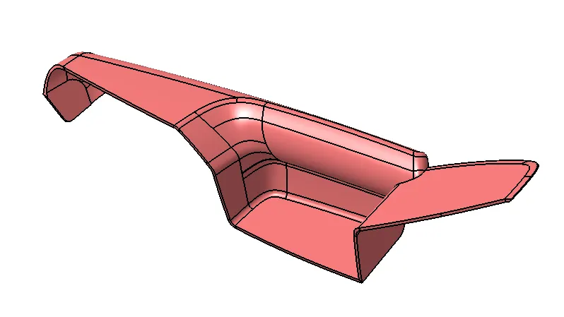
DOOR TRIM COMPONENTS
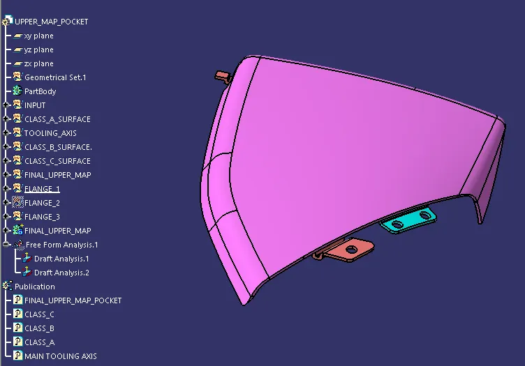
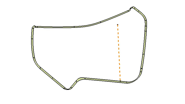
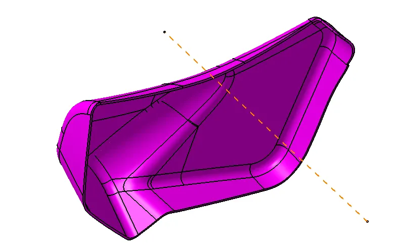
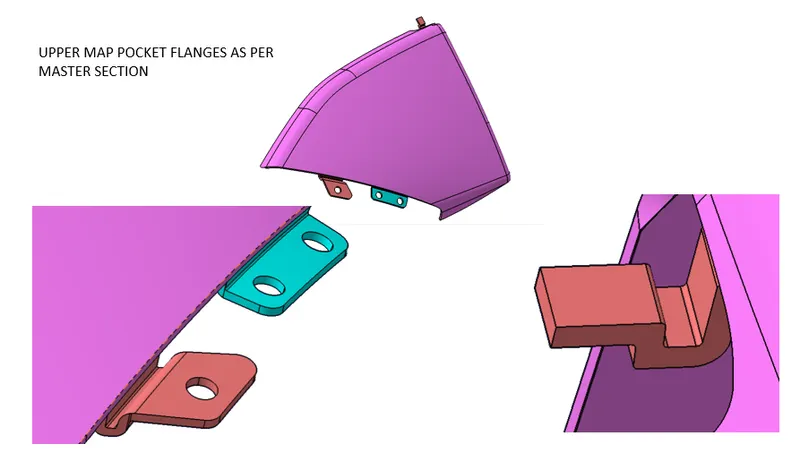
UPPER MAP POCKET
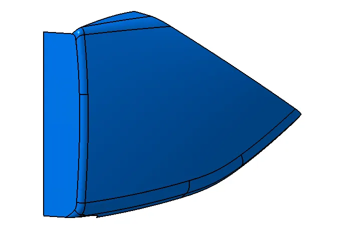
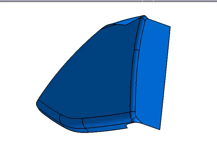
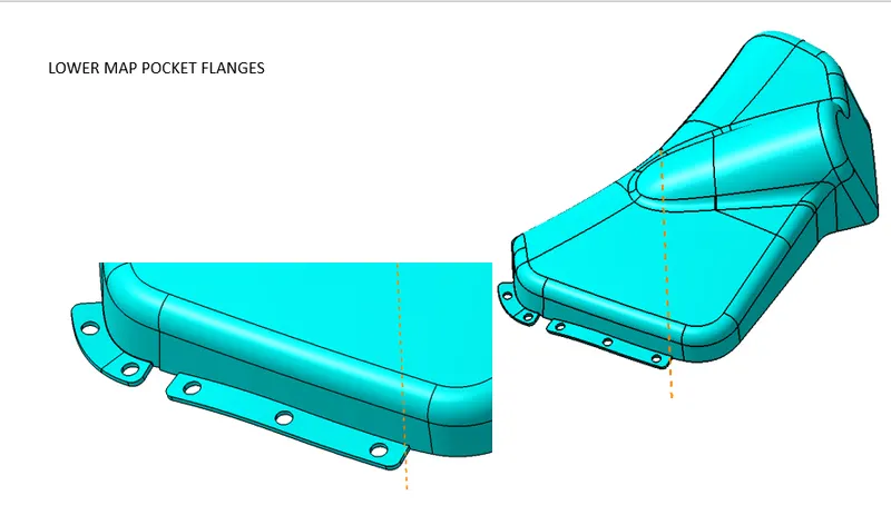
LOWER MAP POCKET
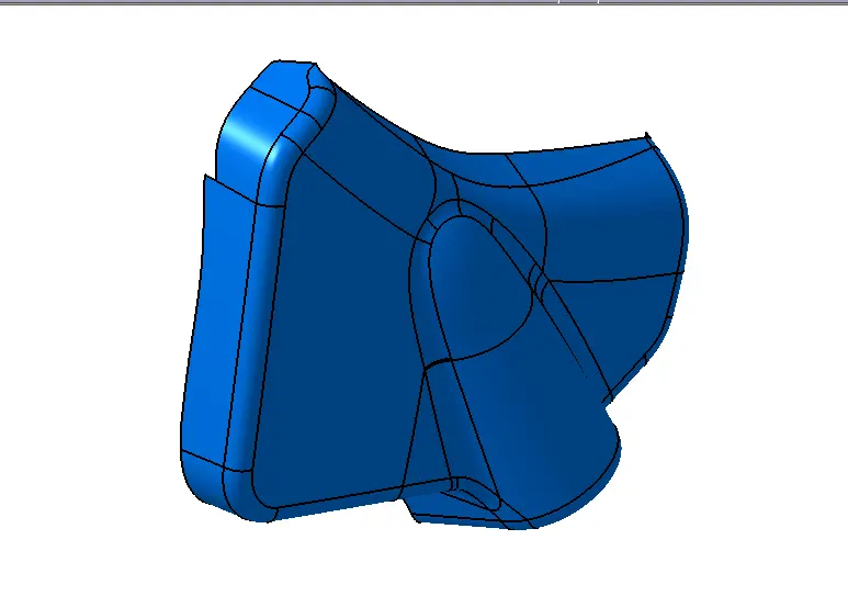
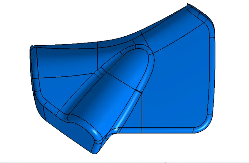
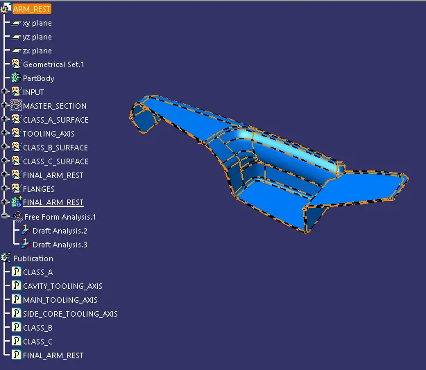
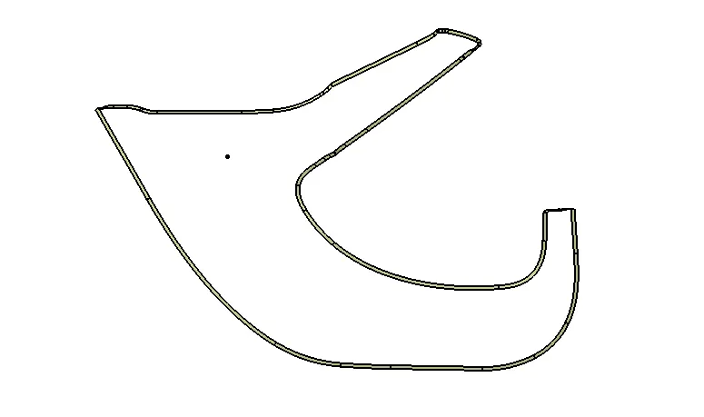
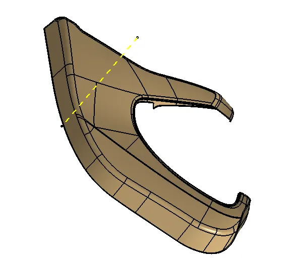
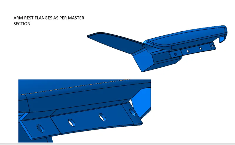
ARM REST
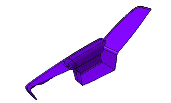
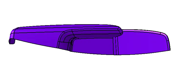
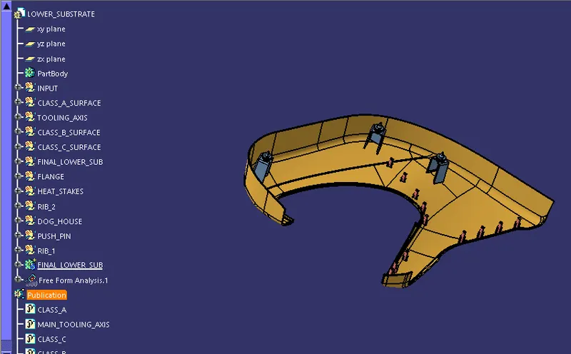
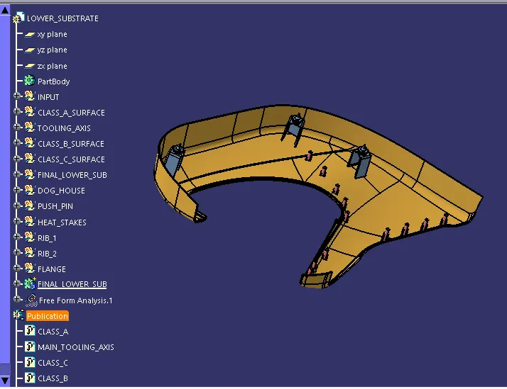
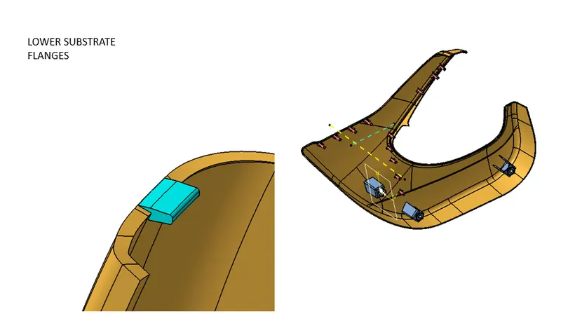
LOWER SUBSTRATE

TOOLING AXIS AND DRAFT ANALYSIS ON CLASS 'A' SURFACE
Now we will be doing Draft analysis on Class ‘A’ Surface, for that we need tooling Axis.
Tooling Axis creation:
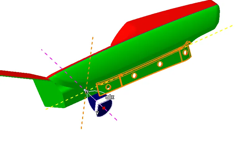
- First, we will extract the base surface of class ‘A’ and on that create the point and then create Axis system at that point.
- As these surfaces are complex and cannot clear the tooling axis. In this situation we need to communicate with class ‘A’ designer and here we are doing this just for practice purpose.
- So that we are creating the tooling axis in Z direction.
- This line is the Main tooling axis for our part.
- After which we will be publishing the tooling axis and class ‘A’ surface.
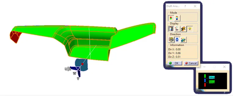
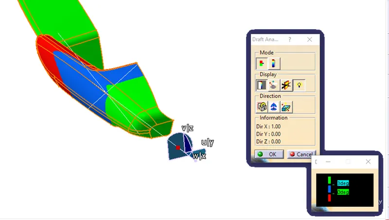
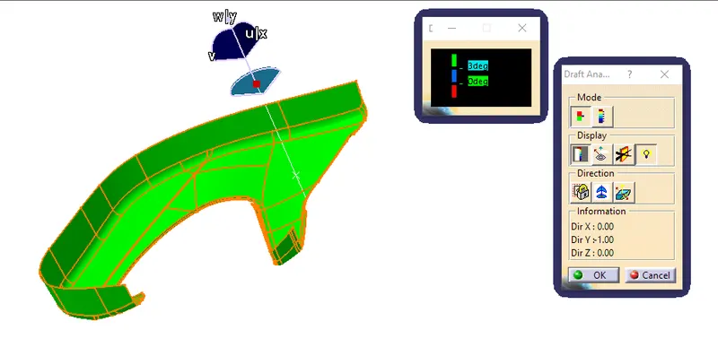
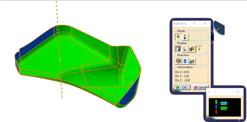
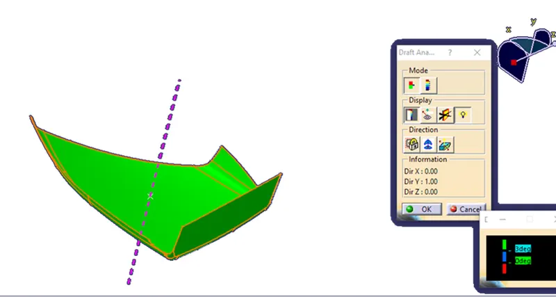
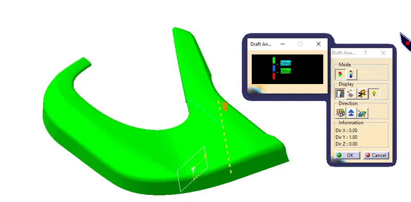
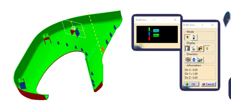
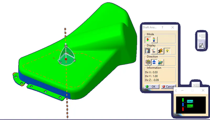
Draft Analysis,
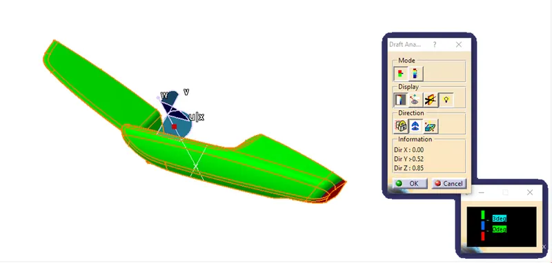
- Insert -> Analysis -> Feature Draft Analysis
- Keep the view mode to material.
- Drag the compass (Direction – compass) on the tooling axis and then select proper direction and lock it.
- Giving draft angle as 3 degree.
‘B’ Surface Creation:
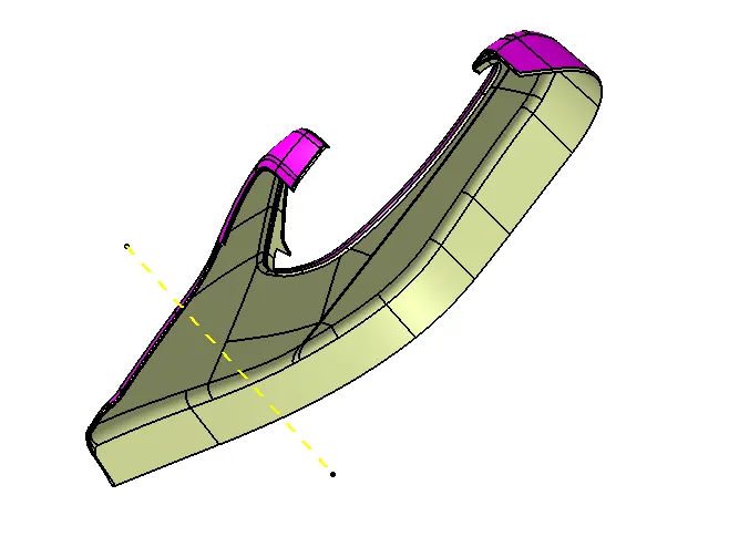
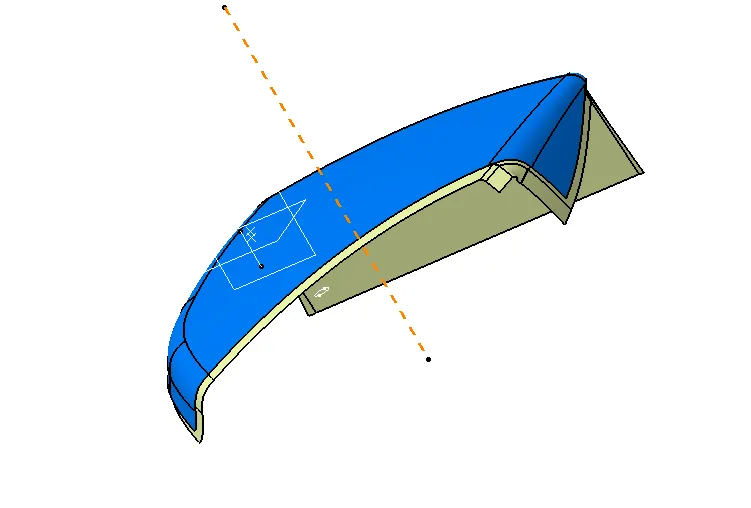
- Extract Class ‘A’ Surface.
- Untrim extracted surfaces.
- Extrapolate to some extend.
- Use trim and select proper surface.
- Offset inward at 2.5 mm
- Use edge fillet,

CLASS 'C' AND SOLID BODY CREATION
‘C’ Surface Creation:
- Take outer boundary using Boundary command of class ‘A’ surface
- Also extract the outer surface for reference purpose.
- Use sweep command to create surface using the extracted boundary and the reference surface.
- Give the sweep surface angle as 93 degree and extend the surface up to 3 to 5mm and select appropriate direction.
- Sweep – profile type ‘line’ – subtype ‘with reference surface’
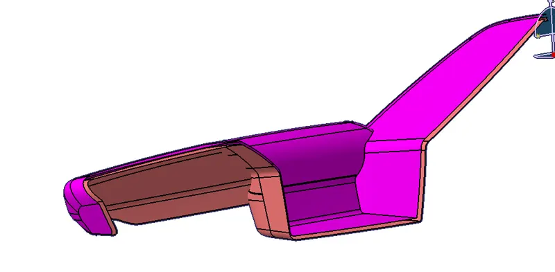
Final Body creation:
- Join class ‘A’ surface and ‘C’ surface.
- Trim resulting surface with ‘B’ surface.
- Join the surface.
- Result is complete close surface.
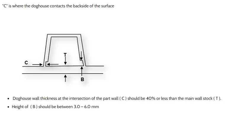
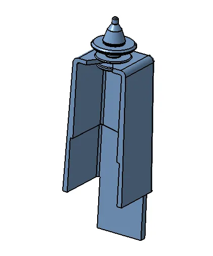
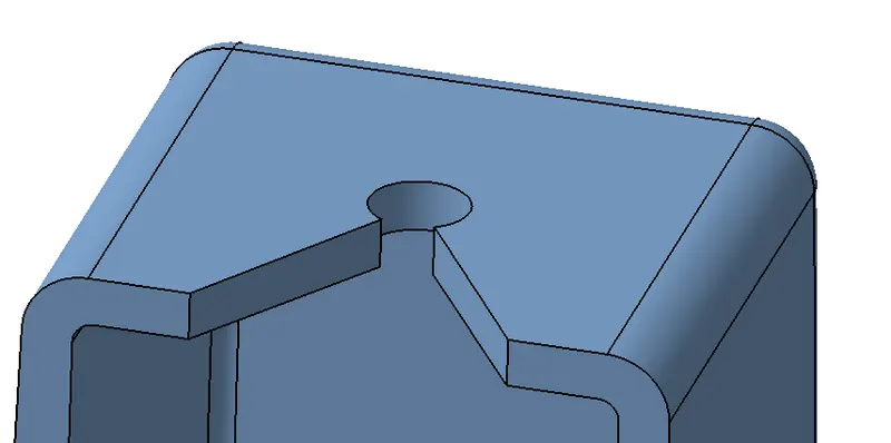
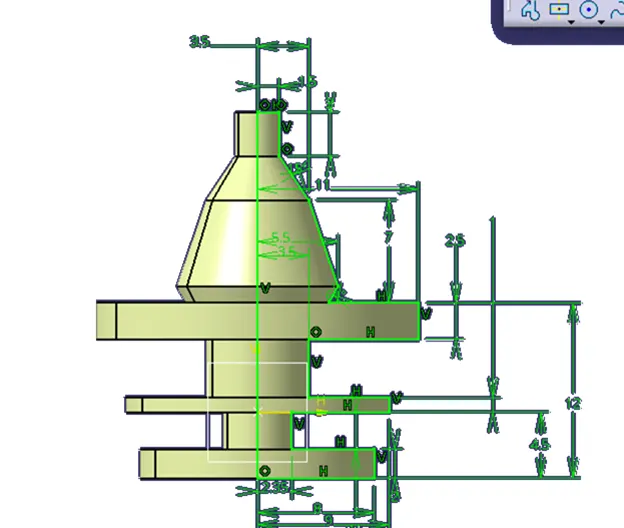
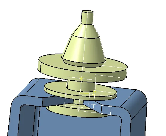
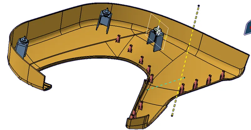
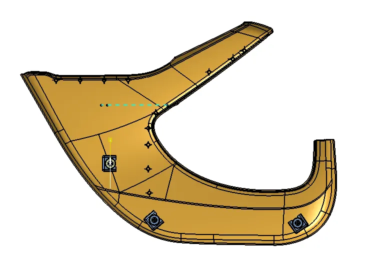
DOG HOUSE AND PUSH PIN DESIGN
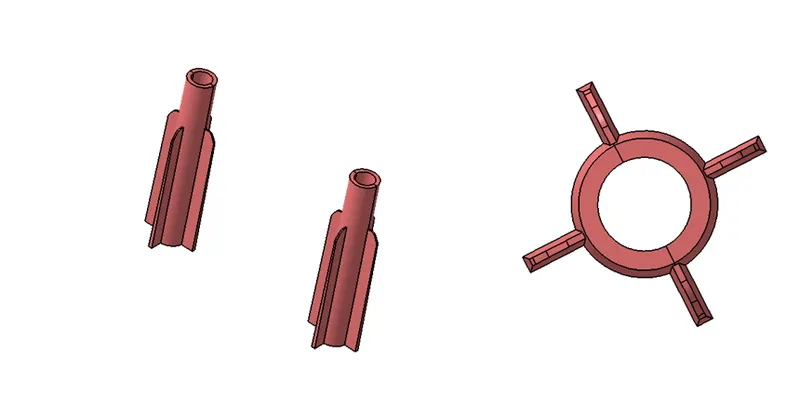
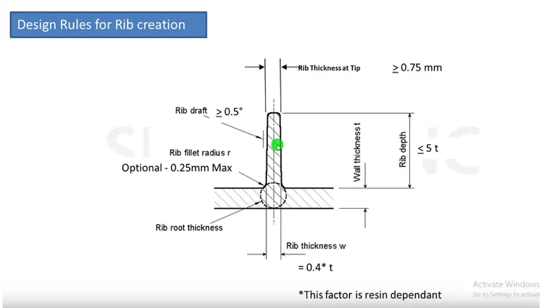
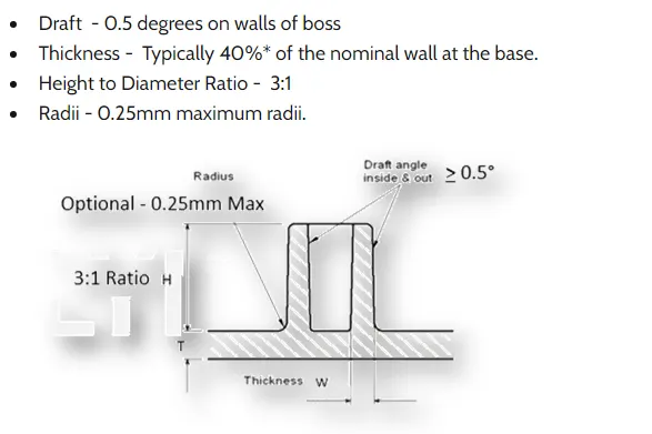
RIBS AND HEAT STAKES
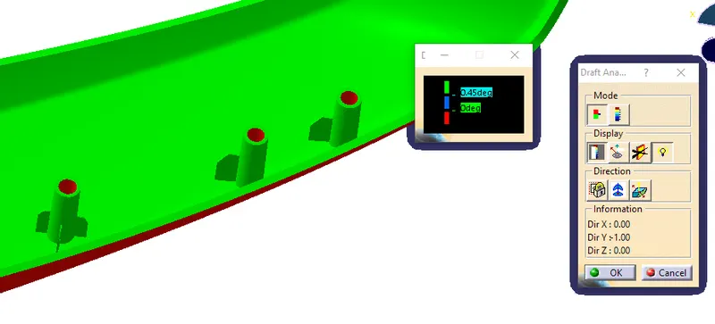
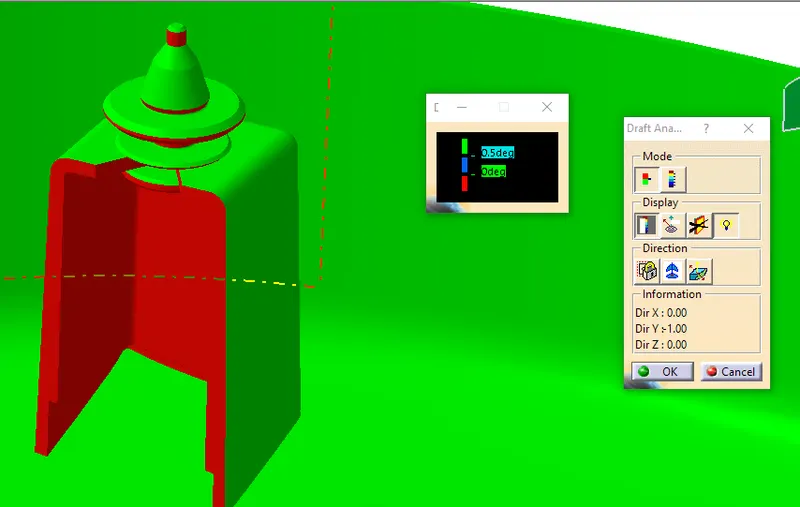
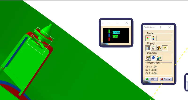
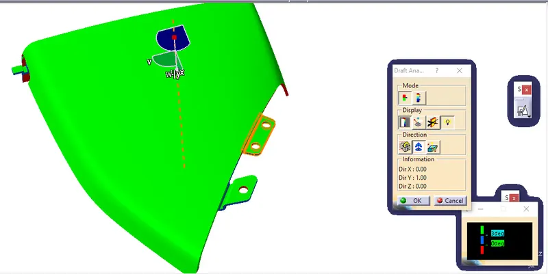
DRAFT ANALYSIS
FINAL ASSEMBLY