Roof challenge
CAR ROOF DESIGN AND ANALYSIS:
What is car Roof:
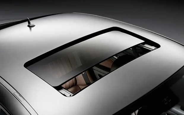
An automobile roof or car top is the portion of an automobile that sits above the passenger compartment, protecting the vehicle occupants from sun, wind, rain, and other external elements.
A roof assembly for a vehicle that includes a center roof panel made from a lightweight material like aluminum, a surrounding attachment flange made from a more formable and stronger material like steel, and a junction that connects the roof panel and the attachment flange together. The aluminum-based roof panel may reduce the overall weight of the assembly, while the steel-based attachment flange may improve its metal forming and attachment capabilities.
- Convertible
- Sunroofs.
- T-tops.
- Targa tops.
- Vinyl

Design Consideration:
- Visibility Criteria
- Head Clearence
- Curvature Study
- Heat Distortion and Snow load Criteria
- Material Thickness
Componants:
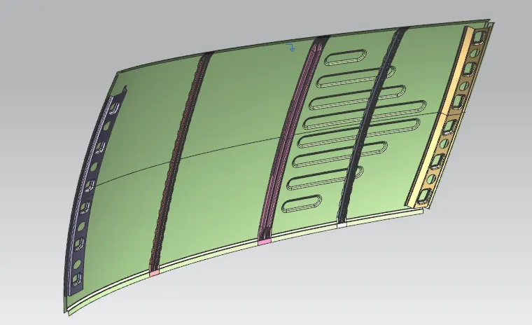
- Roof Outer
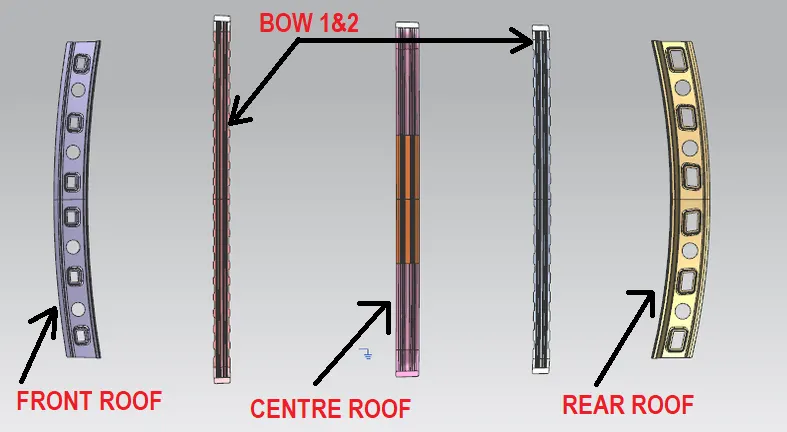
- Front Roof Rail
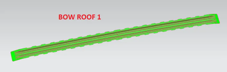
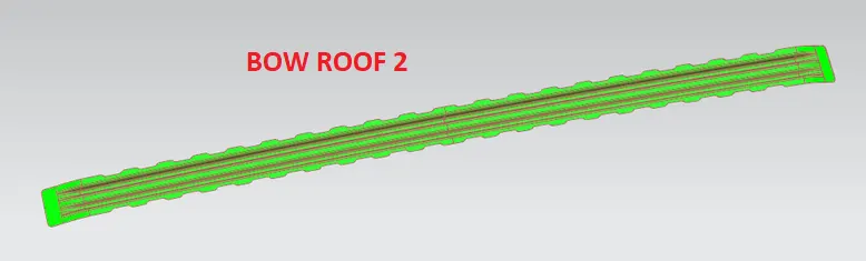
- Bow Roof Rail
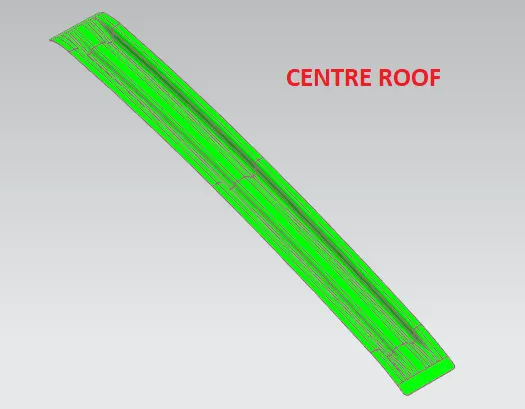
- Center Roof Rail and Reinforcements
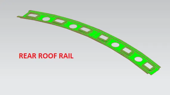
- Rear Roof Rail
Design in NX CAD:
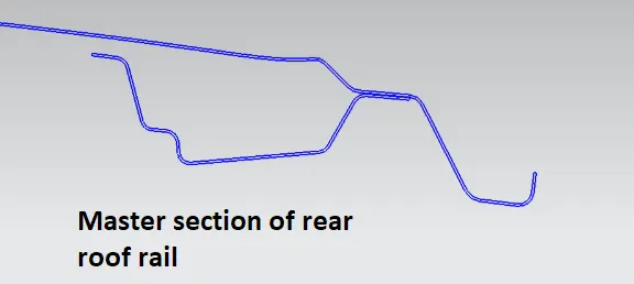
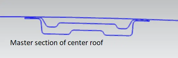
Given Data,
Roof Outer:
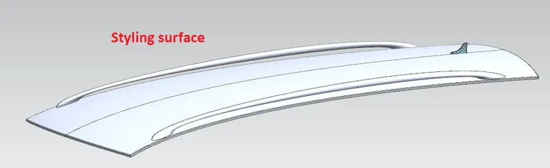
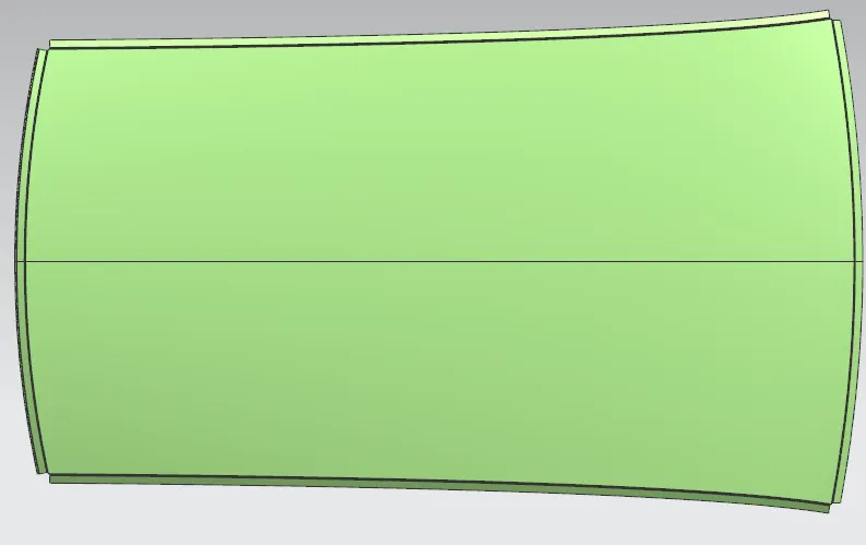
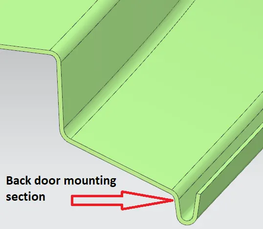
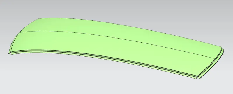
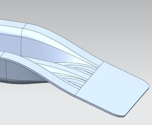
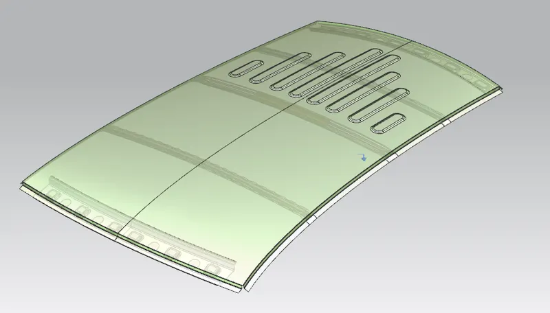
It is outer panel which is given by styling team. In this we are adding flanges for side, front and rear mountings.
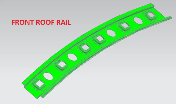
Front Roof Rail:
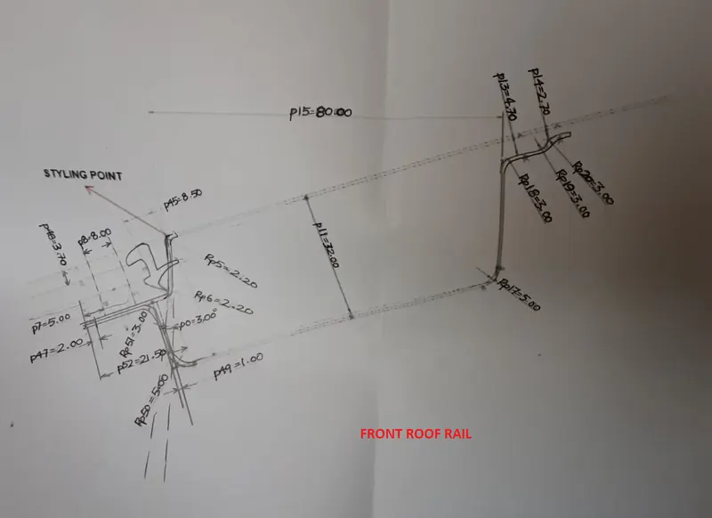
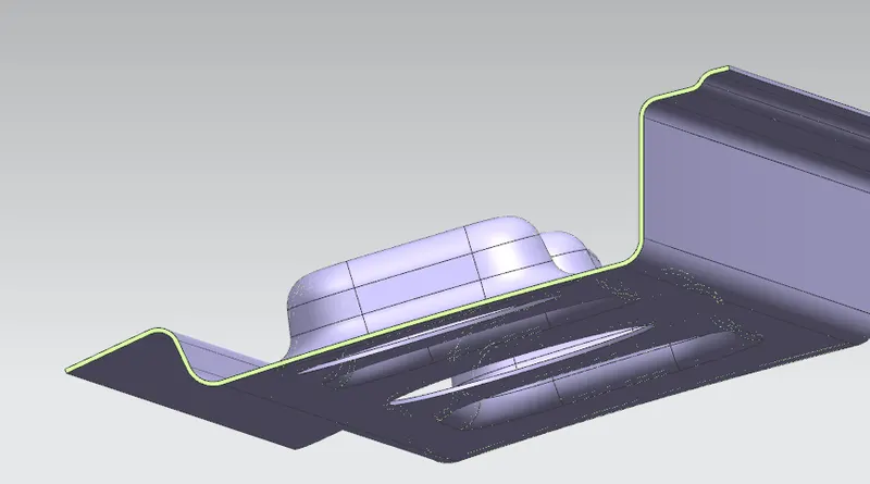
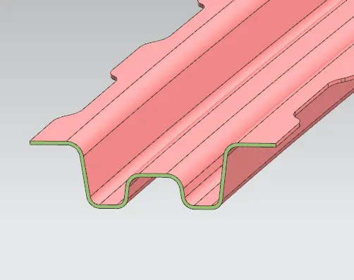
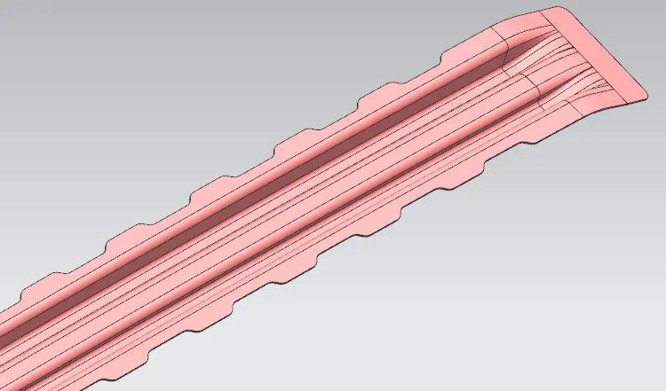
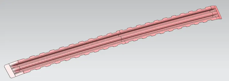
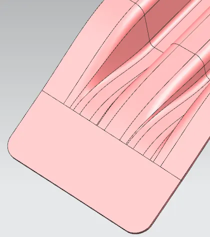
It is used to support the windshield glass, body side outer and inner panel. Usually made from bodyside outer scrap of the thikness 0.75mm with adequete dradt angle for deep drawing.
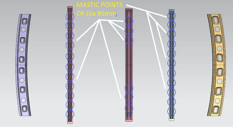
Designed considering the visibility criteria of driver and passengers point of view.Windshield end and roof end is joined using spot weld and other end is joined using mastic sealents.
Embosses and cutouts are gven to increase strength and reduce the weight of part.
Bow Roof 1:
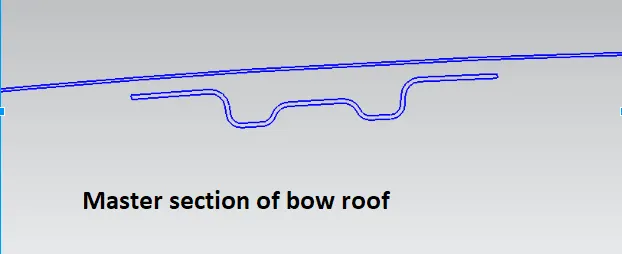
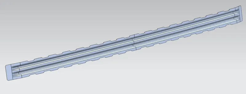
It is the part which is added to provide strength to the longer length roofs. Joined to roof with mastic sealent.
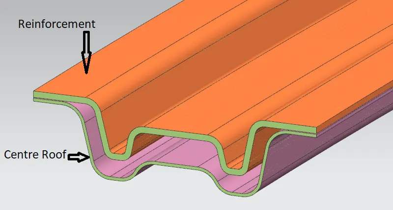
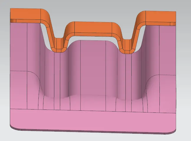
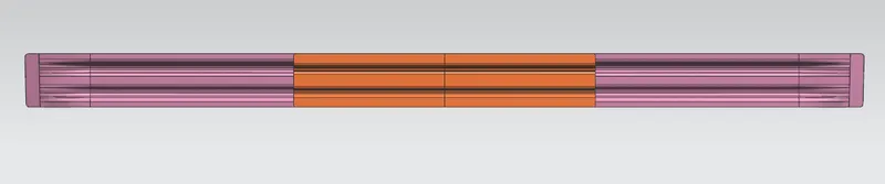
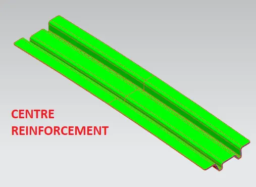
Centre Roof and Reinforcement:
It is cross member that is used in between front and rear roof rails to give proper strength. Reinforcement is also designed to improve the strength having thickness of 1.5 mm.
Joined with center roof with spot welding. center roof rail is joined to outer roof by using mastic sealent.
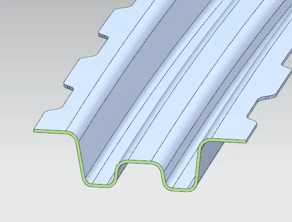
Bow Roof 2:
It is the part which is added to provide strength to the longer length roofs. Joined to roof with mastic sealent.
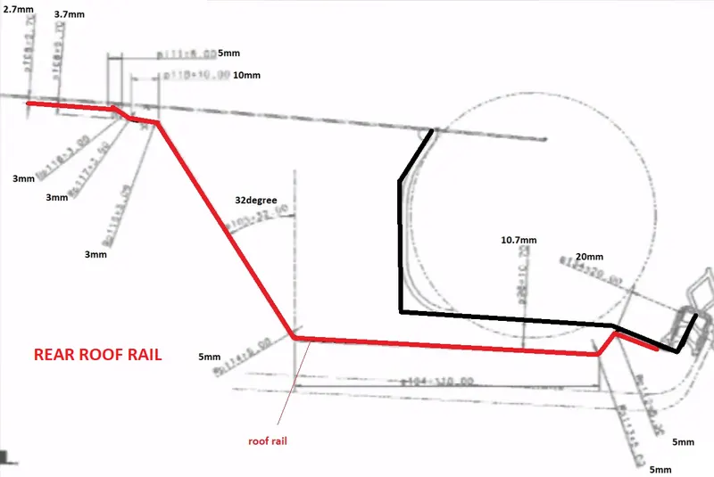
Rear Roof Rail:
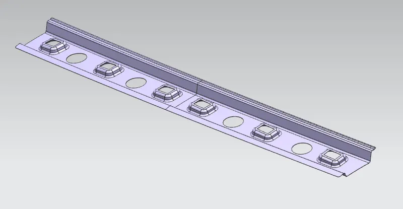
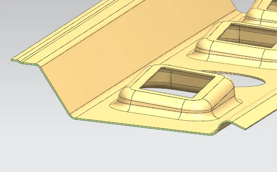
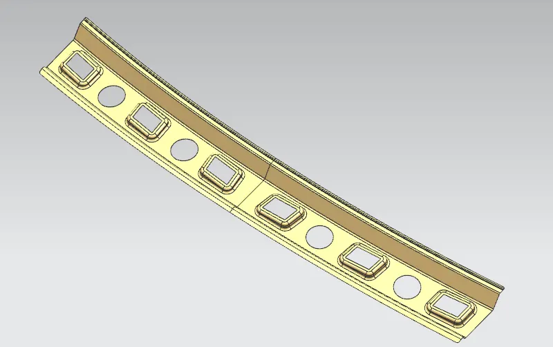
It is the support that joins the backdoor and outer roof with the help of spot welding and the other end id joined to roof by masitc sealents.
Embosses and cutouts are gven to increase strength and reduce the weight of part.
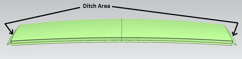
Ditch Area:
It is nothing but adding flanges to the styling surface for different mountings.
Mastic Points:
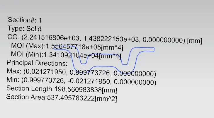
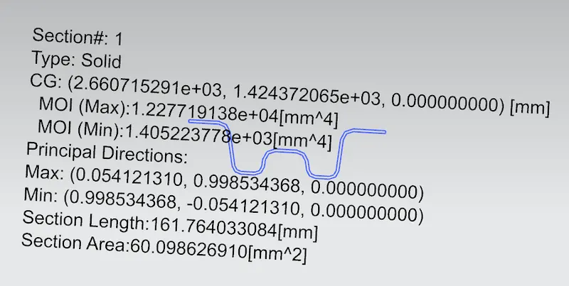
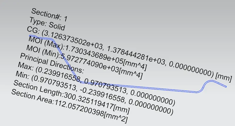
Section Modulus:
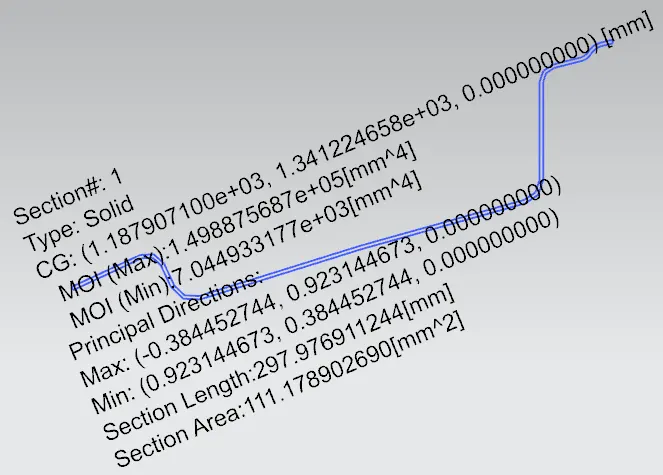
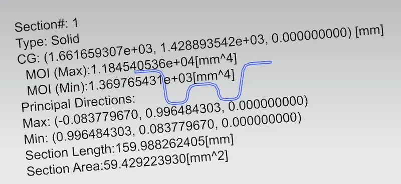
The section modulus of the cross-sectional shape is of significant importance in designing beams. It is a direct measure of the strength of the beam. A beam that has a larger section modulus than another will be stronger and capable of supporting greater loads.
S = I / y
where I is the second moment of area and y is the distance from the neutral axis to any given fibre.
1.Front Roof Rail:
2.Bow Roof 1:
3.Centre Roof and Reinforcement:
4.Bow Roof 2:
5.Rear Roof Rail:
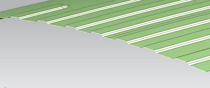
Draft Analysis:
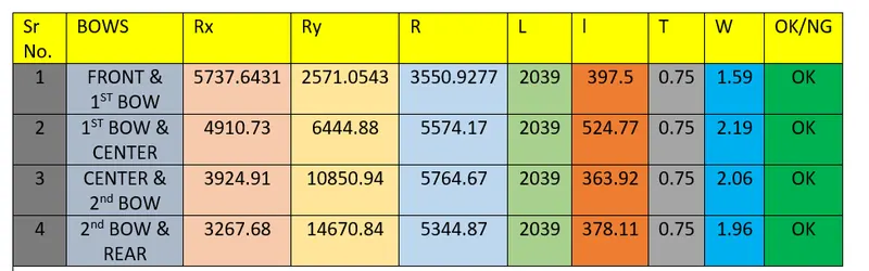
Heat Distortaion calculation:
W = [1.73 x 10^(-3) x L] + [1.85 x 10^(-8) x (R^2)/t] + [ 1.10x10^(-3) x l] - 2.68
Judgement Condition : OK< 2.7> 3.1
Where
L = Roof Length in X-Direction[mm](Roof dimension in 0-Y)
R = Roof curvature
R = 2(Rx*Ry)/(Rx+Ry)
Rx = X curvature
Ry = Y curvature
t = Roof plate thickness [mm]
l = Bow Roof Span [mm]
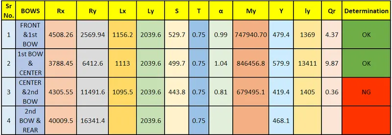
Snow Load Criteria:
Qr = [Iy x t2] / [α x s x [(Rx + Ry)/2]2 x 10-8]
Where,
α = My x Lx2 x 10-12 , My = Y(Ly-Y)
Judgement condition = Qr ≥ 3.1
250 ≤ s ≤ 380
t = Roof plate thickness [mm]
Ly = Distance between the front and rear roof Rails on the Vehicle along with 0Y[mm]
Length of Roof panel with the centre point between Roof rail Front /Rear as the reference point of the front and the rear.
Lx = Distance between the Left and Right end of the roof on the Roof BOW [mm]
Width of the roof panel exposed on the surface.
Y = Distance from Front Roof Rail to Roof BOW[mm]
s = Distance for which Roof BOW bears divided load [mm]
s = L1/2 + L2/2
Iy = Geometrical moment of inertia of Roof BOW (Y cross-section) [mm4]
Rx = Lateral direction curvature radius of roof panel Y cross-section on Roof BOW [mm]
Roof panel curvature Radius of the Length Lx in Front view
Ry = Longitudinal Direction curvature radius of the Roof panel X cross-section on Roof BOW [mm]
Roof panel X curvature radius of length s in Side view
Final Result: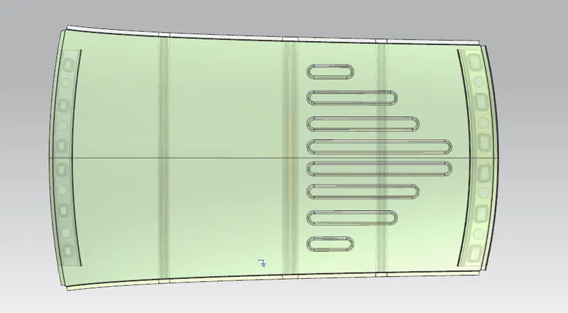
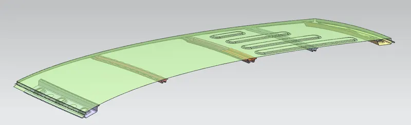
File is available at google drive: https://drive.google.com/drive/folders/1iOrGFWS4GPyYCUueKhKHQrkjcvjYIuKp?usp=sharing