Week 11 - Final project
INPUTS:
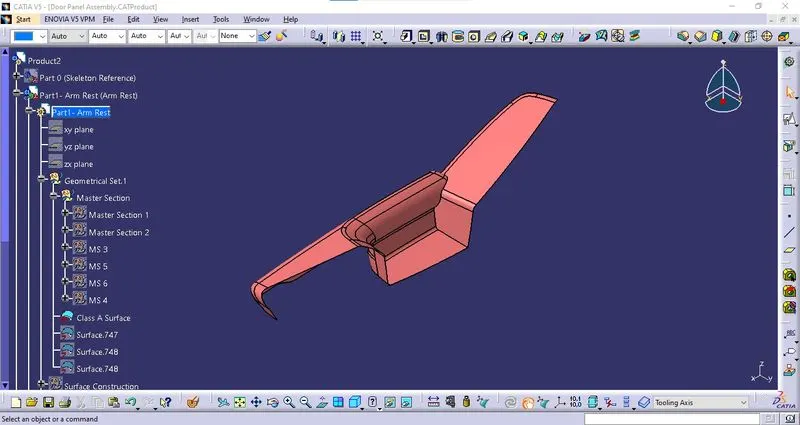
Class A - Arm Rest:
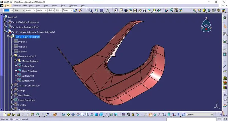
Class A - Lower Substrate:
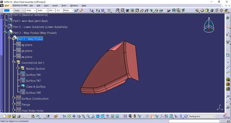
Class A - Map Pocket:
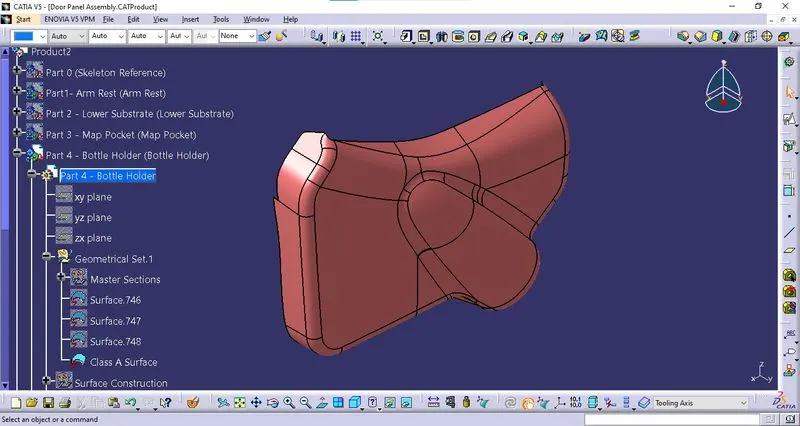
Class A - Bottle Holder:
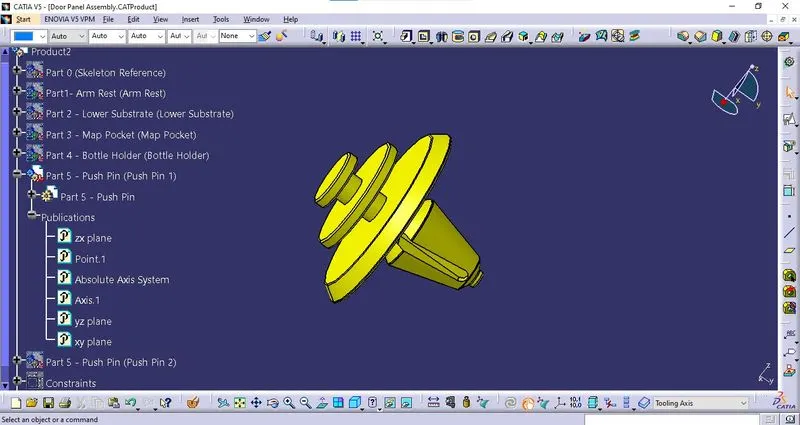
Part Body - Push Pin:
Master Sections:
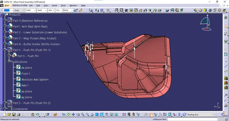
COMPONENTS:
Part 1 - Arm Rest:
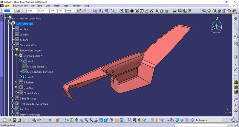
The Class A surface has issues in the surface built and with the approval, The improvements have been made on the surface to make it usable.
Improved Class A:
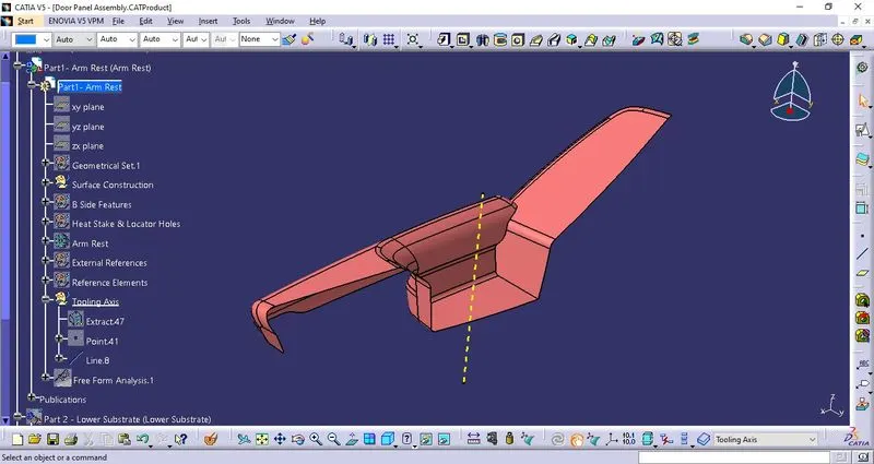
Tooling Axis:
The tooling axis was created along the Z direction since that will be the most appropriate direction.
Draft Analysis of Class A:
Draft analysis is done on the Class A Surface with respect to the Tooling Axis created.
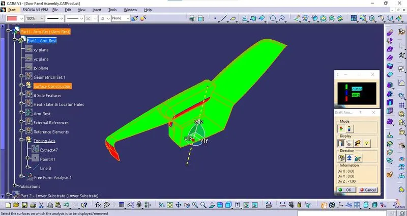
The draft angle was given as 2.9 degrees. There is an error in the draft analysis of the Class A Surface. The component will not clear along the tooling axis. This is because of the defective Class A surface.
B Surface:
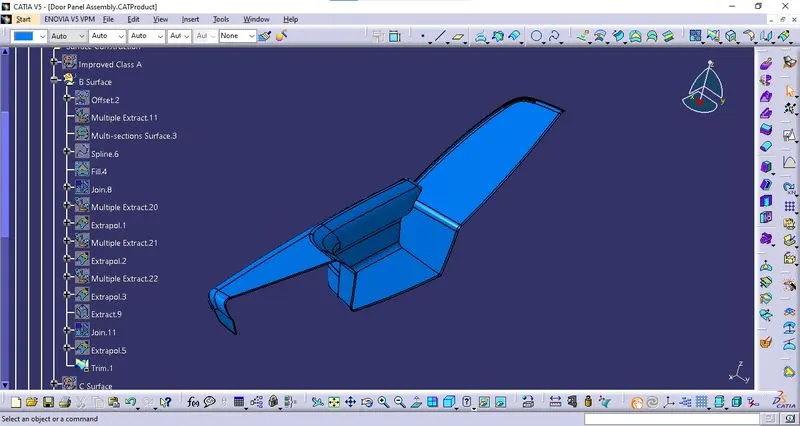
Class B was created by offsetting Class A to the thickness of the component, (i.e.) 2.5 mm which is found in the master section. The imperfect boundaries are repaired and joined into a single surface and B Surface is formed. The commands used here are Offset, Join, Multi Section Surface, Fill, Sweep, Extract, Multiple Extract, Trim and Extrapolate.
C Surface:
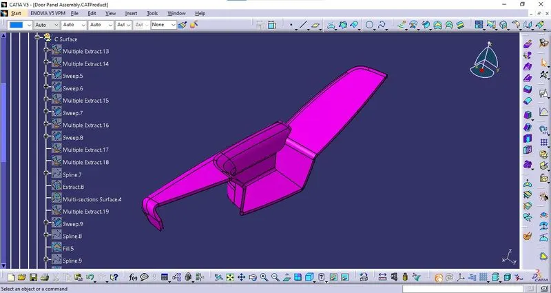
The boundary is created on the Class A Surface and a sweep was done with the boundary as a guiding curve and Class A Surface as a reference surface at 90 degrees. This sweep is then joined with the Class A Surface to form C Surface.
Closed Surface:
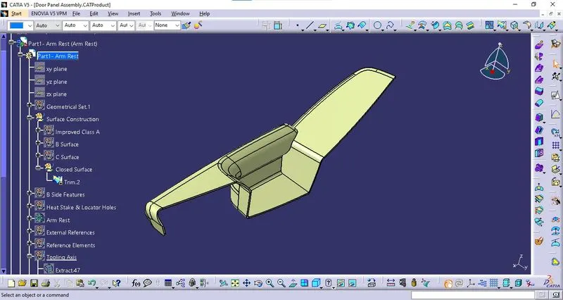
In the final stage of the surface creation, The Class A Surface and Class B Surface are trimmed together to form an appropriate closed surface.
Part Body - Arm Rest:
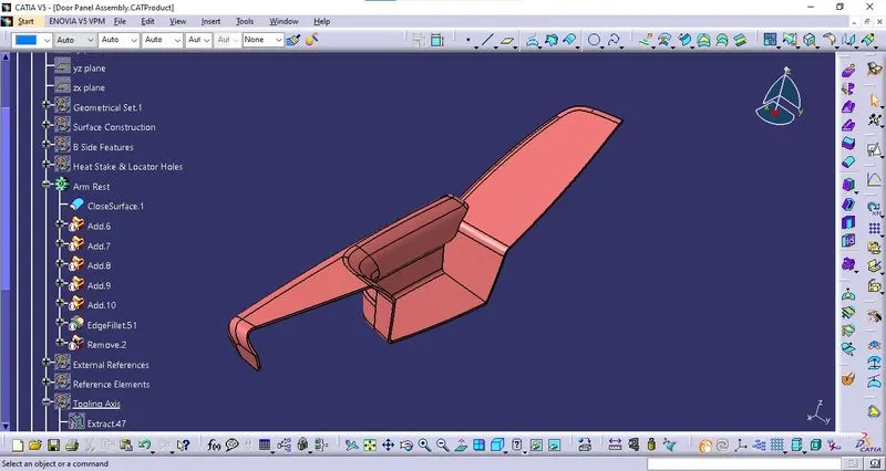
The part body is created using the close Surface command in Part Workbench with Closed Surface as the reference surface.
Fixation Features:
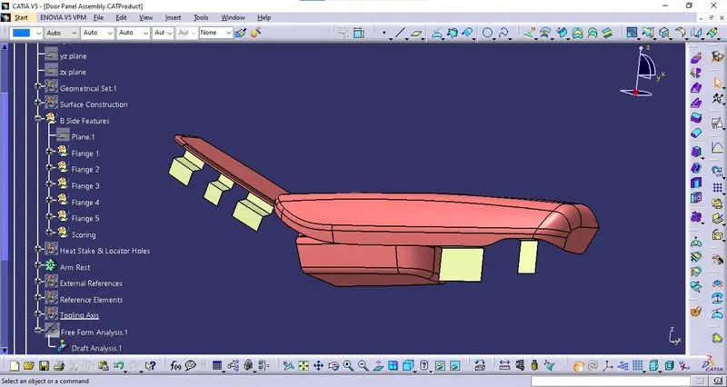
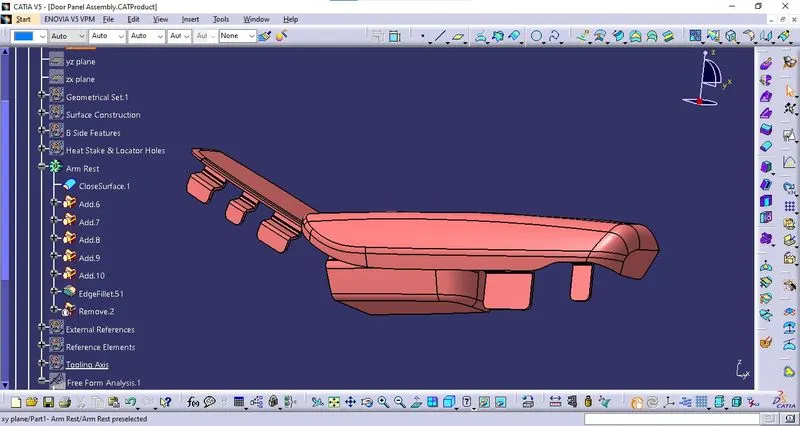
Multiple flanges are made with respect t the master section for the purpose of fixation of the part.
Initially, it is created as a surface and then thickened.
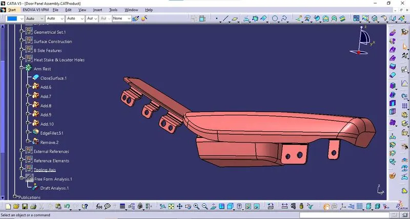
Heat stake & Locator Holes:
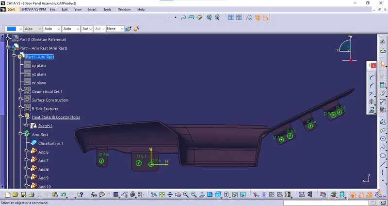
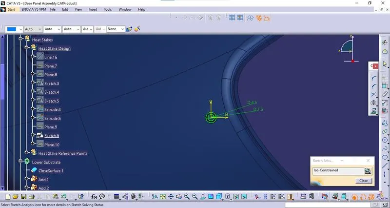
The holes for the heat Stakes & Locators are drawn in a sketch with a clearance of 0.05mm on each side along the reference points. Then, this sketch is removed with the existing component.
Draft Analysis - Component:
Draft analysis is done on the Component with respect to the Tooling Axis created.
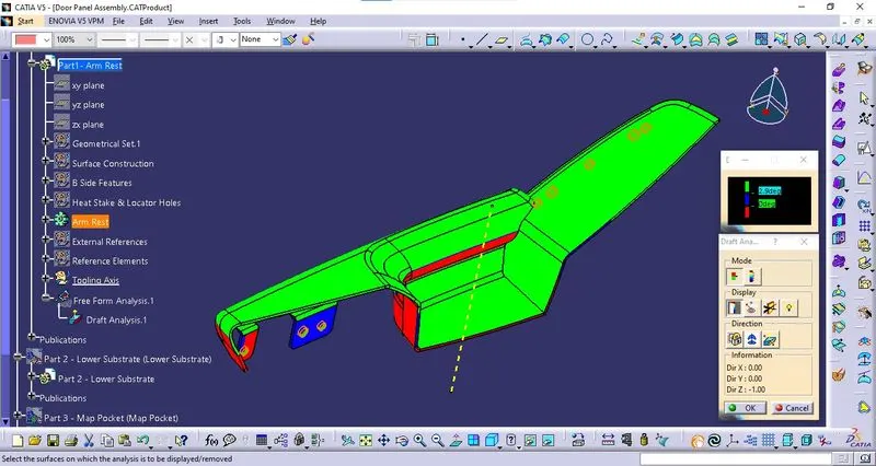
The draft angle is given a 2.9 Degree. The component will not clear along the tooling axis. This is because of the defective Class A surface.
Publication:
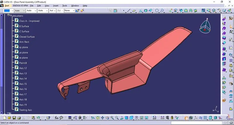
During this process of designing and assembling the Component, The Objects which are used frequently are published for ease of operation. Published Objects are,
- A Surface.
- Tooling Axis
- B Surface
- C Surface
- Closed Surface
- XY Plane
- YZ Plane
- ZX Plane
- Reference Point
- Axis along the holes of heat stakes & Locators.
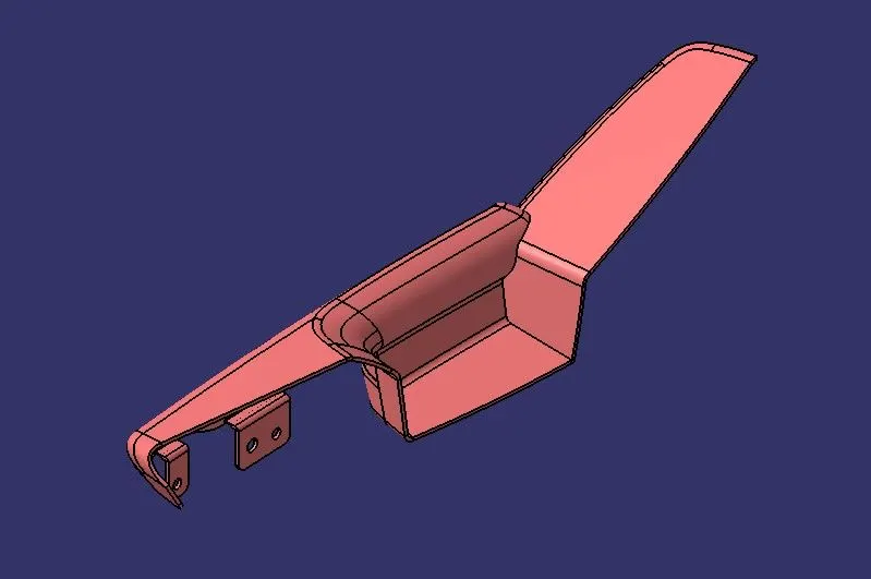
Component - Orientation Views:
Isometric View:
Front View:
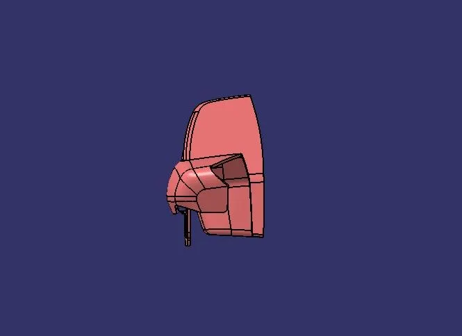
Side View:
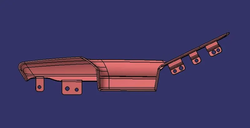
Top View:
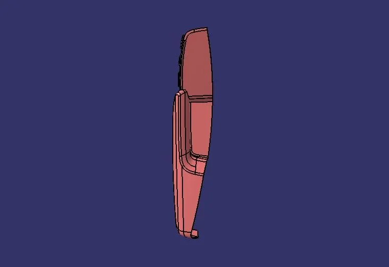
Part 2 - Lower Substrate:
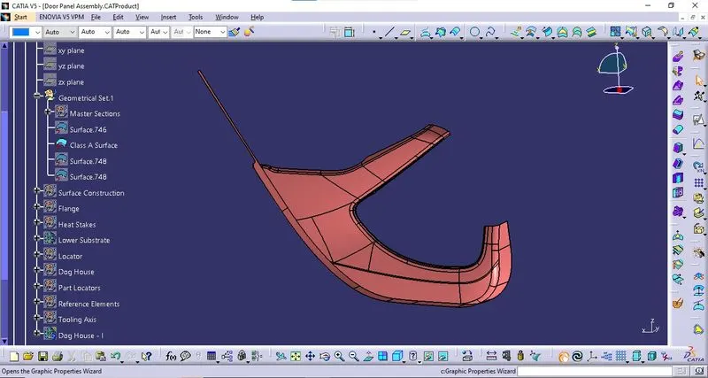
Class A Surface:
The input for the lower substrate is a Class A Surface.
Tooling Axis:
The tooling axis was created along the Y direction since that will be the most appropriate direction.
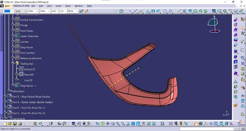
Draft Analysis of Class A:
Draft analysis is done on the Class A Surface with respect to the Tooling Axis created.
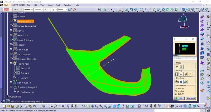
The Draft angle was given as 2.9 degrees. The component will clear due to the adequate draft is given.
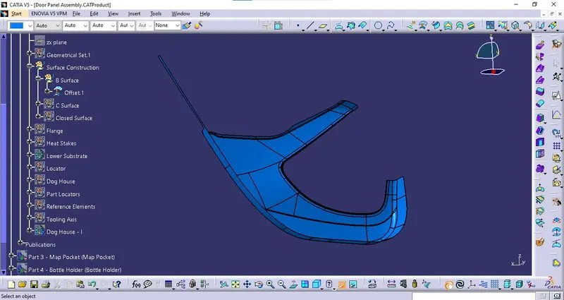
B Surface:
Class B was created by offsetting Class A to the thickness of the component, (i.e.) 2.5 mm which is found in the master section.
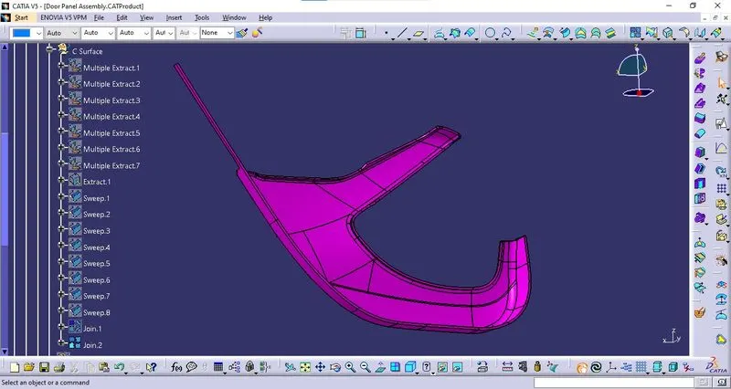
C Surface:
The boundary is created on the Class A Surface and a sweep was done with the boundary as a guiding curve and Class A Surface as a reference surface at 90 degrees. This sweep is then joined with the Class A Surface to form C Surface.
Closed Surface:
In the final stage of the surface creation, The Class A Surface and Class B Surface are trimmed together to form an appropriate closed surface.
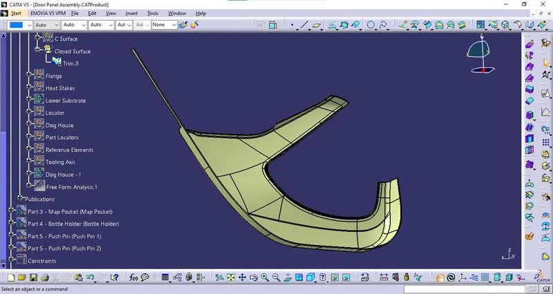
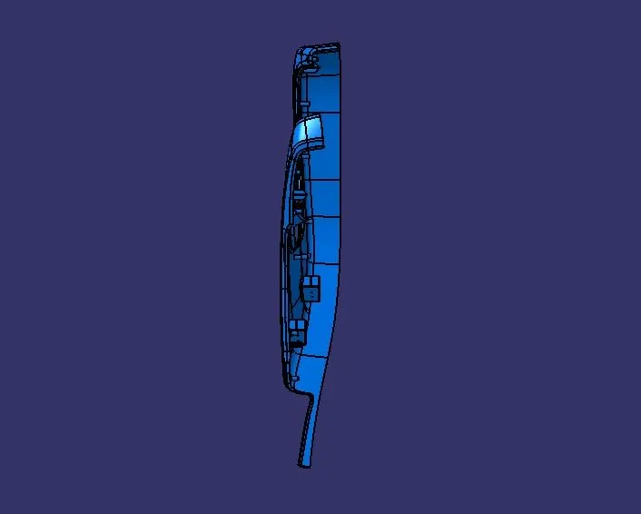
Part Body - Lower Substrate:
The part body is created using the close Surface command in Part Workbench with Closed Surface as the reference surface. (The image has B side features also)
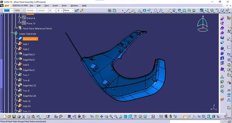
B side / Engineering Features:
Flange:
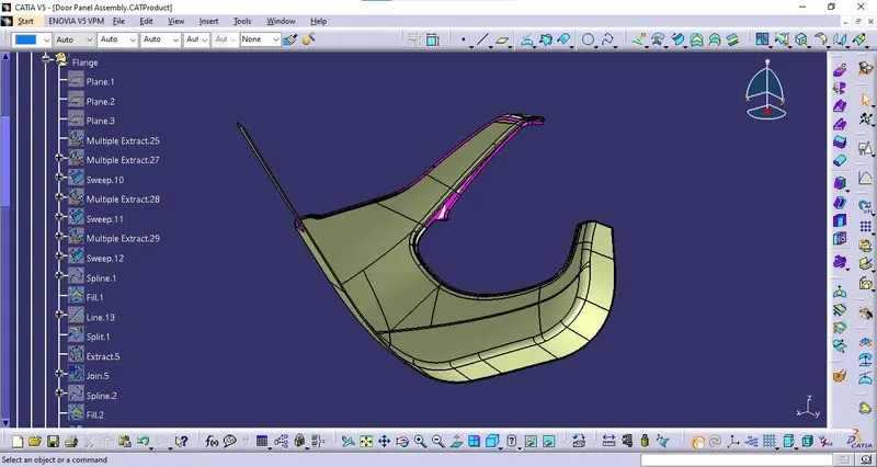
Flanges were created with the master section as the reference.
Heat stake Assembly 1:
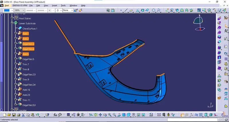
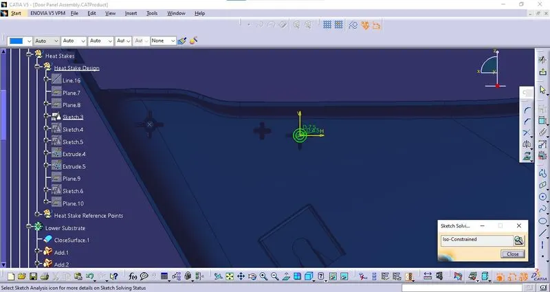
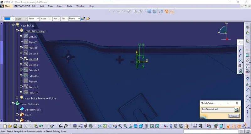
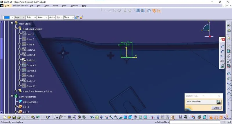
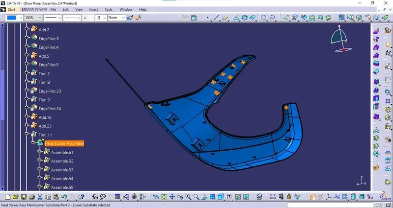
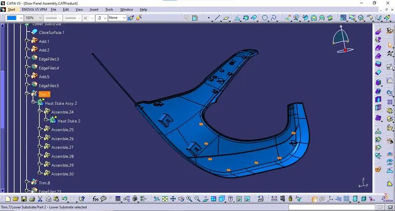
The heat stake assembly 1 is created to attach the Arm Rest & Map Pocket to the Lower substrate.
Heat stake Assembly 2:
The heat stake assembly 2 is created to attach the bottle holder to the Lower substrate.
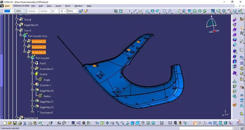
Part Locator:
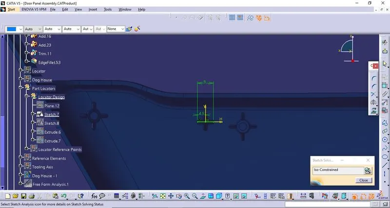
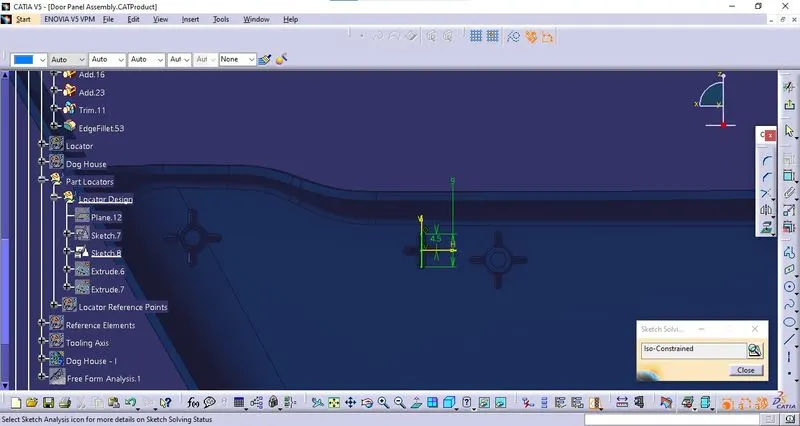
The part locators are used to locate the Arm Rest in position.
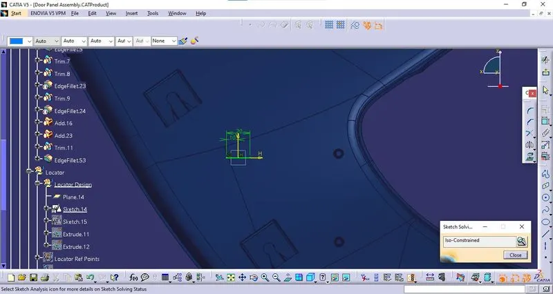
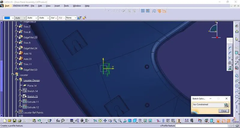
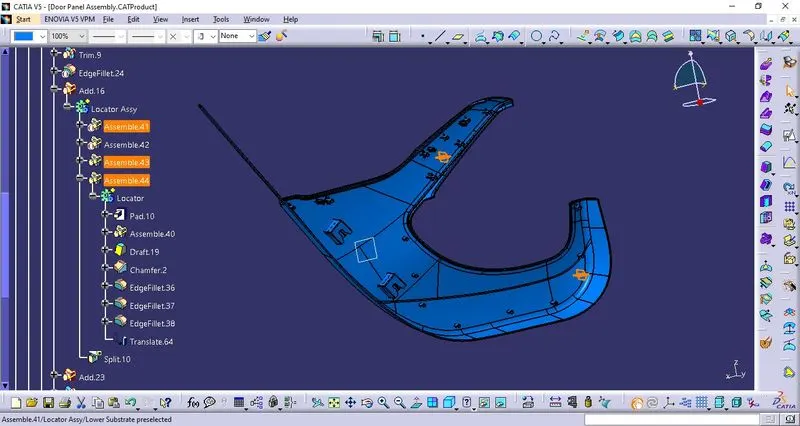
Locator:
The locators are given in order to locate the door pad assembly into the BIW.
Dog House:
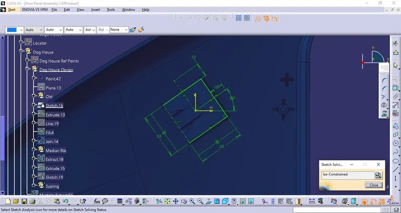
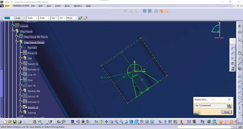
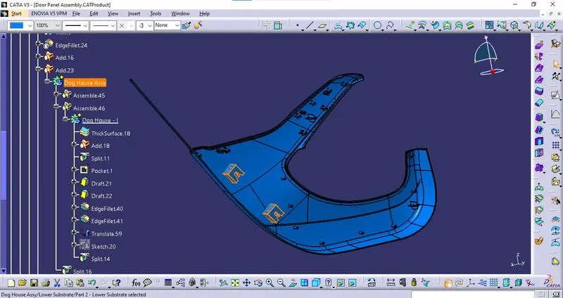
The Dog house feature is provided to fix the push pin which will fix the Door Panel Assembly to the BIW
Draft Analysis - Component:
Draft analysis is done for the component with respect to the Tooling Axis.
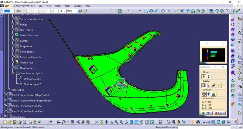
The draft angle was given as 2.9 degrees. The component will clear due to an adequate draft angle.
Draft Analysis - Engineering Features:
Draft analysis is done for the component with respect to the Tooling Axis.
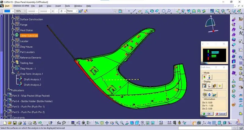
The draft angle was given as 0.49 degrees. The component will clear due to an adequate draft angle.
Publication:
During this process of designing and assembling the Component, The Objects which are used frequently are published for ease of operation. Published Objects are,
- A Surface.
- Tooling Axis
- B Surface
- C Surface
- Closed Surface
- XY Plane
- YZ Plane
- ZX Plane
- Reference Point
- Axis along the heat stakes & Locators.
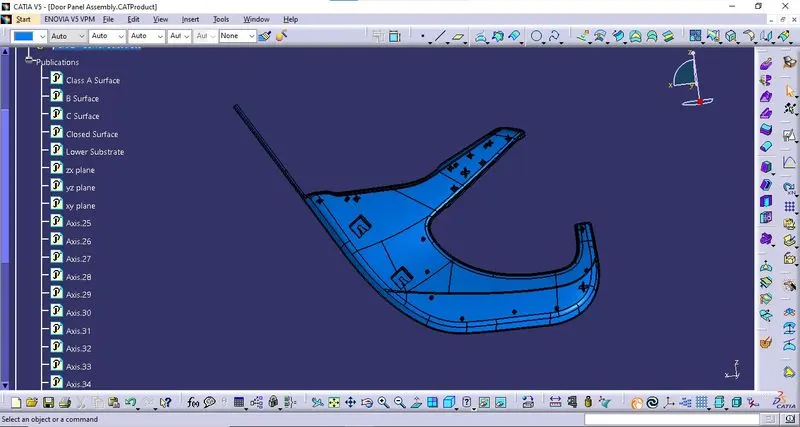
Component - Orientation Views:
Isometric View:
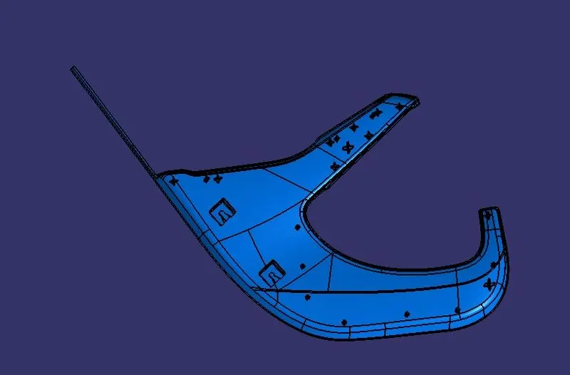
Front View:
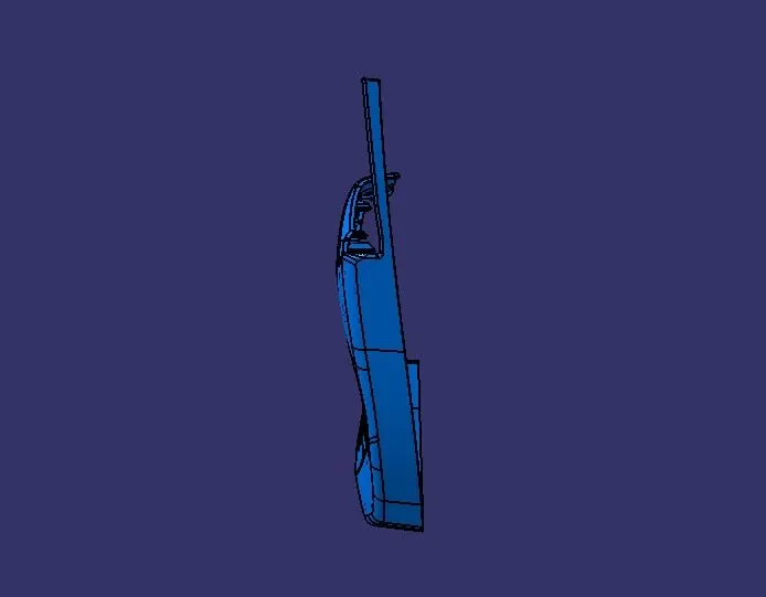
Side View:
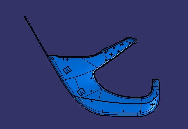
Top View:
Part 3 - Map Pocket:
Class A Surface:
The input for the Map Pocket is a Class A Surface.
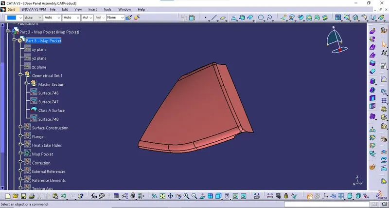
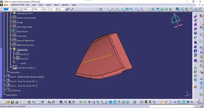
Tooling Axis:
The tooling axis was created along the Y direction since that will be the most appropriate direction.
Draft Analysis of Class A:
Draft analysis is done on the Class A Surface with respect to the Tooling Axis created.
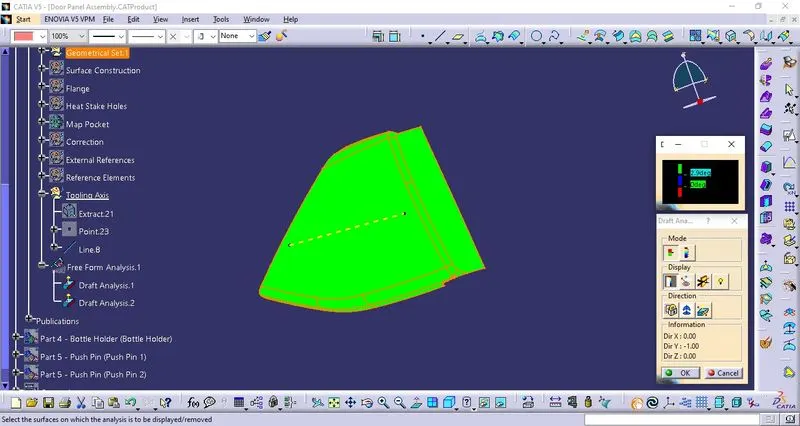
The Draft angle was given as 2.9 degrees. The component will clear due to the adequate draft is given.
B Surface:
Class B was created by offsetting Class A to the thickness of the component, (i.e.) 2.5 mm which is found in the master section. The imperfect boundaries are repaired and joined into a single surface and B Surface is formed. The commands used here are Offset, Spline, Join, Multi Section Surface, Fill, Extract and , Multiple Extract.
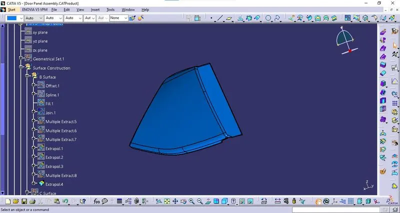
C Surface:
The boundary is created on the Class A Surface and a sweep was done with the boundary as a guiding curve and Class A Surface as a reference surface at 90 degrees. This sweep is then joined with the Class A Surface to form C Surface.
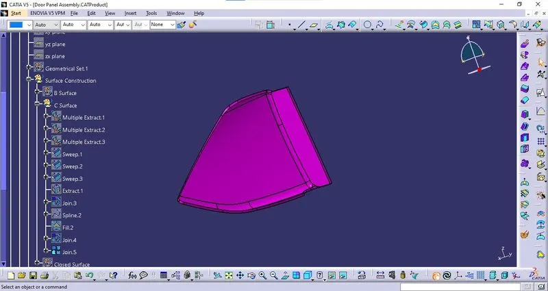
Closed Surface:
In the final stage of the surface creation, The Class A Surface and Class B Surface are trimmed together to form an appropriate closed surface.
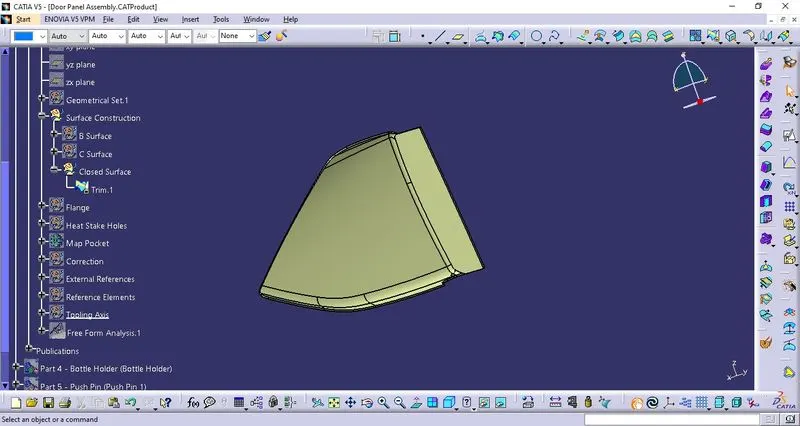
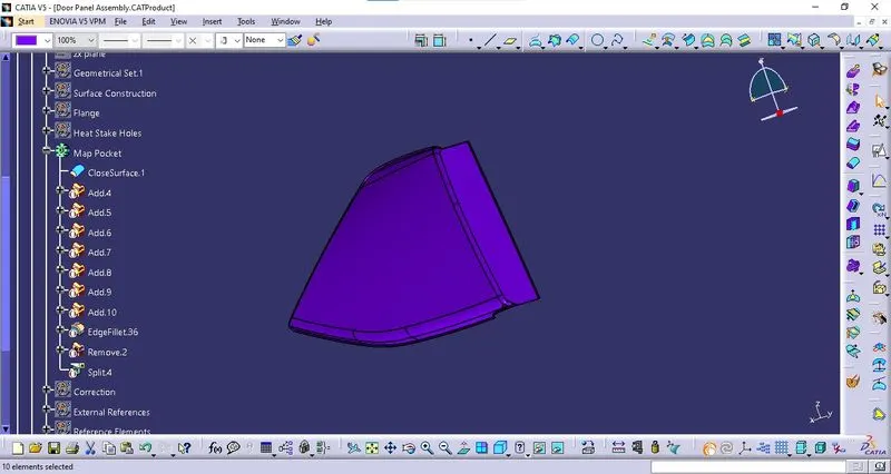
Part Body - Map Pocket:
The part body is created using the close Surface command in Part Workbench with Closed Surface as the reference surface.
B side / Engineering Features:
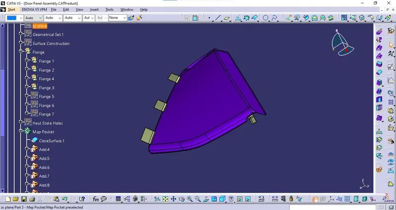
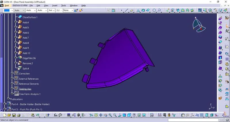
Flange:
Flanges were created to fix the component with Lower Substate and Bottle Holder and it is designed with the master section as the reference.
Heat stake Holes:
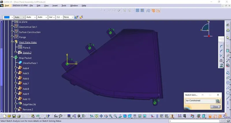
The holes for the heat Stakes are drawn in a sketch with a clearance of 0.05mm on each side along the reference points. Then, this sketch is removed from the existing component.
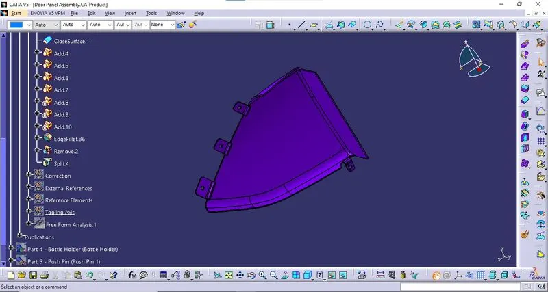
Draft Analysis - Component:
Draft analysis is done on the Component with respect to the Tooling Axis created.
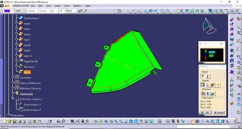
The Draft angle was given as 2.9 degrees. The component will clear due to the adequate draft given.
Publication:
During this process of designing and assembling the Component, The Objects which are used frequently are published for ease of operation. Published Objects are,
- A Surface.
- Tooling Axis
- B Surface
- C Surface
- Closed Surface
- XY Plane
- YZ Plane
- ZX Plane
- Reference Point
- Axis along the holes of heat stakes.
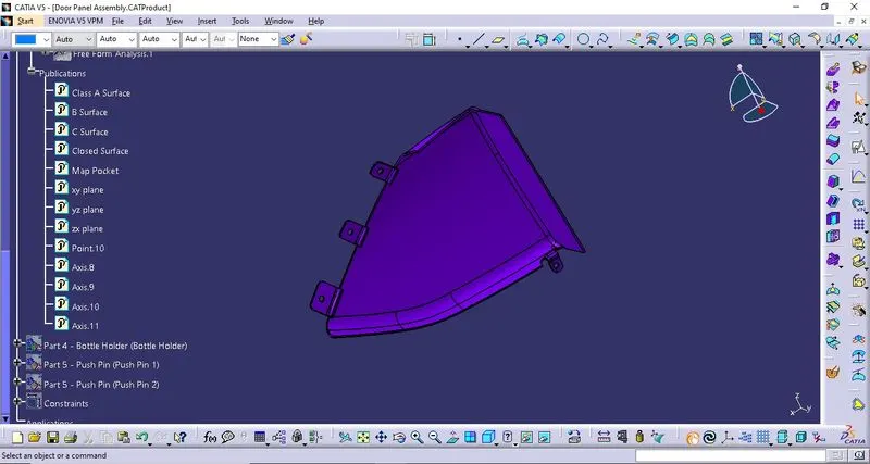
Component - Orientation Views:
Isometric View:
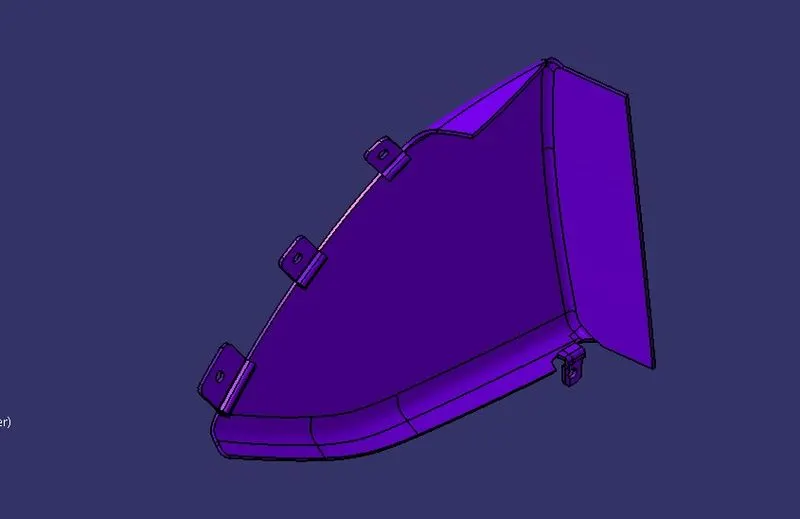
Front View:
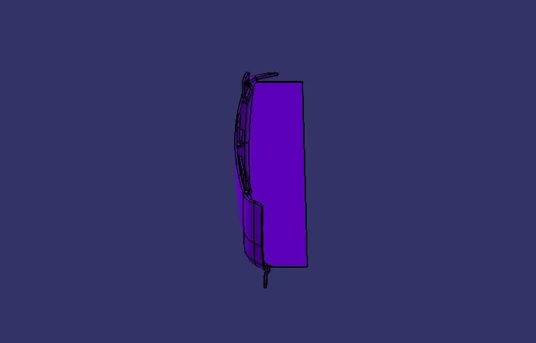
Side View:
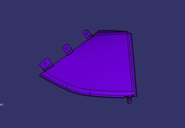
Top View:
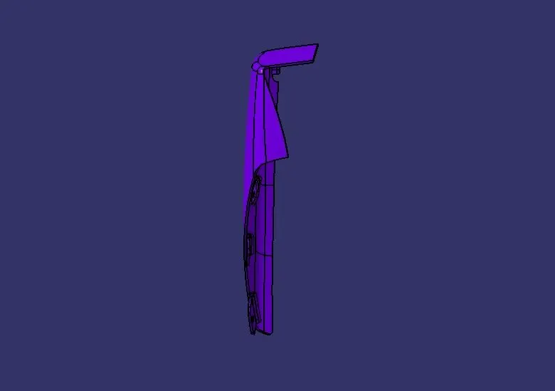
Part 4 - Bottle Holder:
Class A Surface:
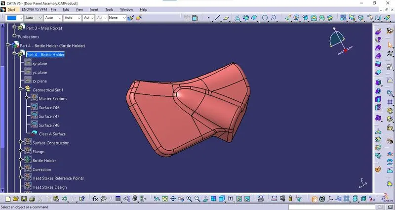
The input for the Bottle Holder is a Class A Surface.
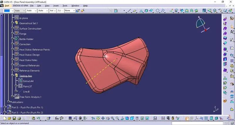
Tooling Axis:
The tooling axis was created along the Y direction since that will be the most appropriate direction.
Draft Analysis of Class A:
Draft analysis is done on the Class A Surface with respect to the Tooling Axis created.
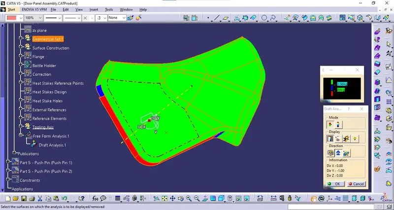
The draft angle was given as 2.9 degrees. There is an error in the draft analysis of the Class A Surface. The component will not clear along the tooling axis. This is because of the defective Class A surface.
B Surface:
Class B was created by offsetting Class A to the thickness of the component, (i.e.) 2.5 mm which is found in the master section.
C Surface:
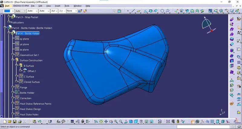
The boundary is created on the Class A Surface and a sweep was done with the boundary as a guiding curve and Class A Surface as a reference surface at 90 degrees. This sweep is then joined with the Class A Surface to form C Surface.
Closed Surface:
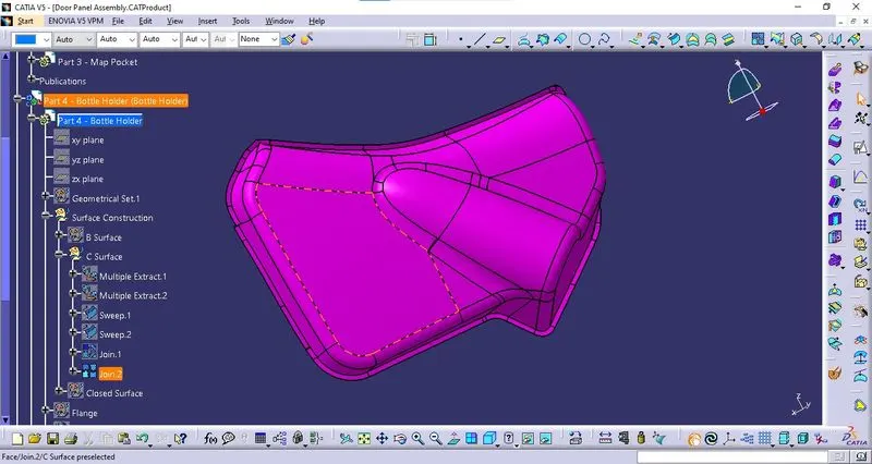
In the final stage of the surface creation, The Class A Surface and Class B Surface are trimmed together to form an appropriate closed surface.
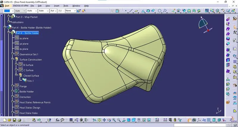
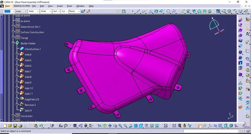
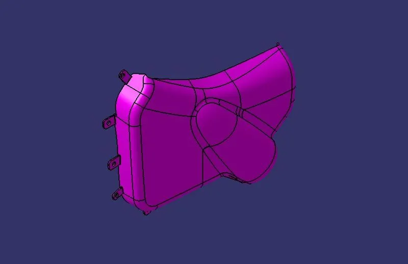
Part Body - Bottle Holder:
The part body is created using the close Surface command in Part Workbench with Closed Surface as the reference surface.
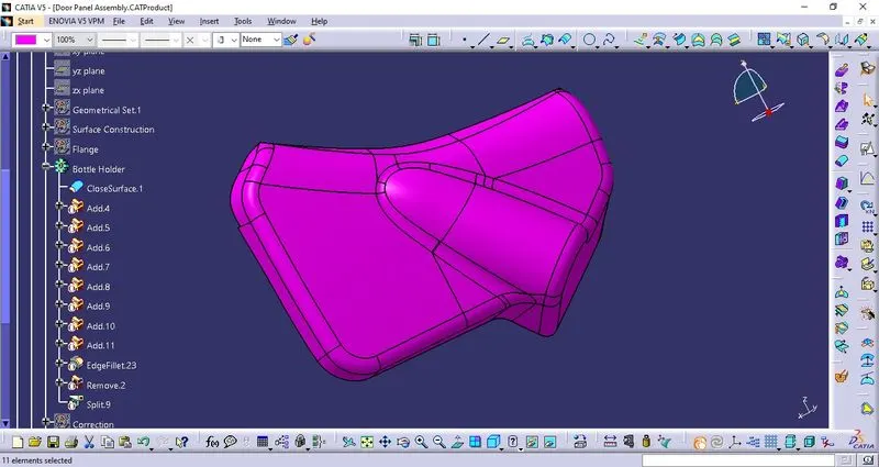
B side / Engineering Features:
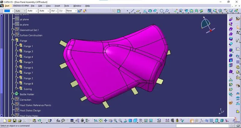
Flange:
Flanges were created to fix the component with Lower Substateand it is designed with the master section as the reference.
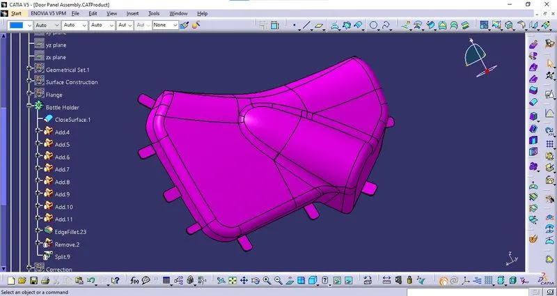
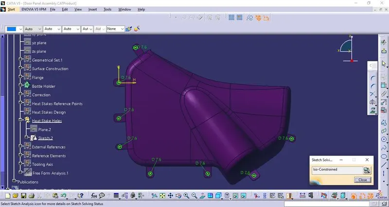
Heat stake Holes:
The holes for the heat Stakes are drawn in a sketch with a clearance of 0.05mm on each side along the reference points. Then, this sketch is removed from the existing component.
Draft Analysis - Component:
Draft analysis is done on the Component with respect to the Tooling Axis created.
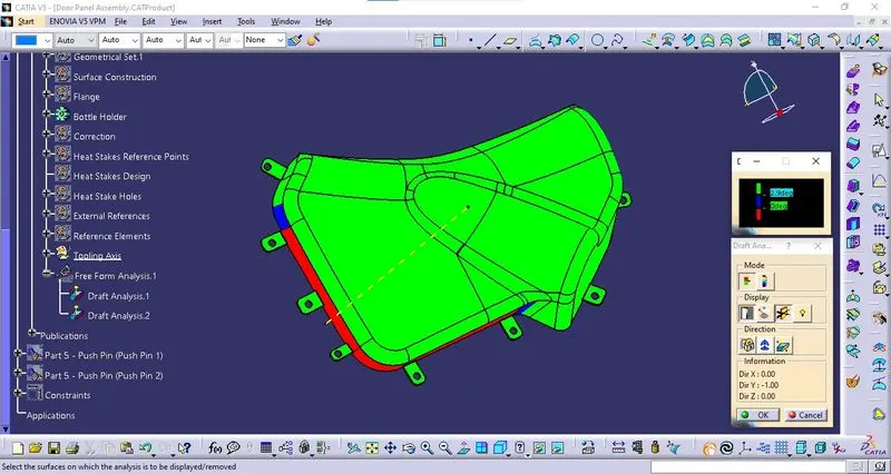
The draft angle is given a 2.9 Degree. The component will not clear along the tooling axis. This is because of the defective Class A surface.
Publication:
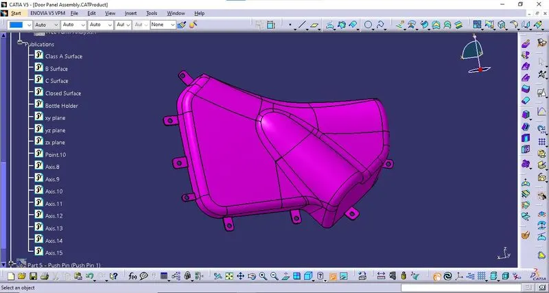
During this process of designing and assembling the Component, The Objects which are used frequently are published for ease of operation. Published Objects are,
- A Surface.
- Tooling Axis
- B Surface
- C Surface
- Closed Surface
- XY Plane
- YZ Plane
- ZX Plane
- Reference Point
- Axis along the holes of heat stakes.
Component - Orientation Views:
Isometric View:
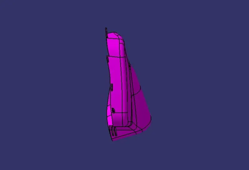
Front View:
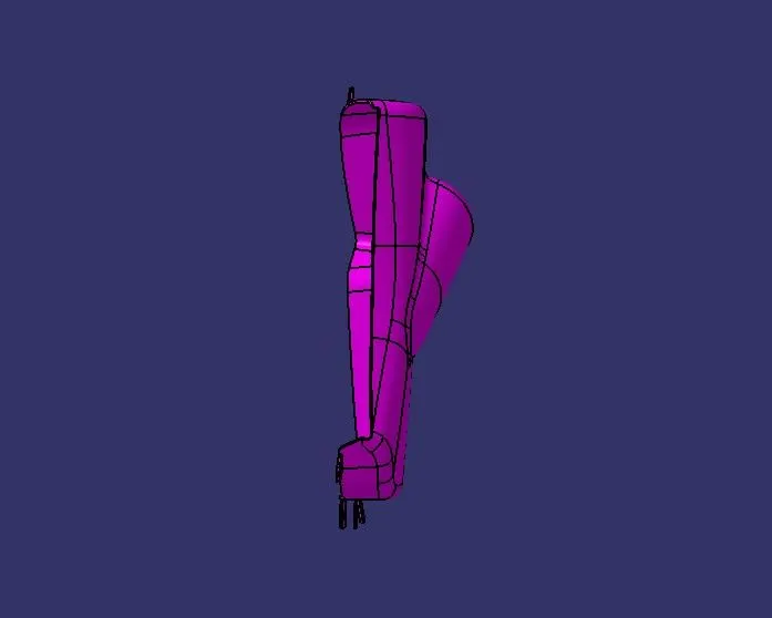
Side View:
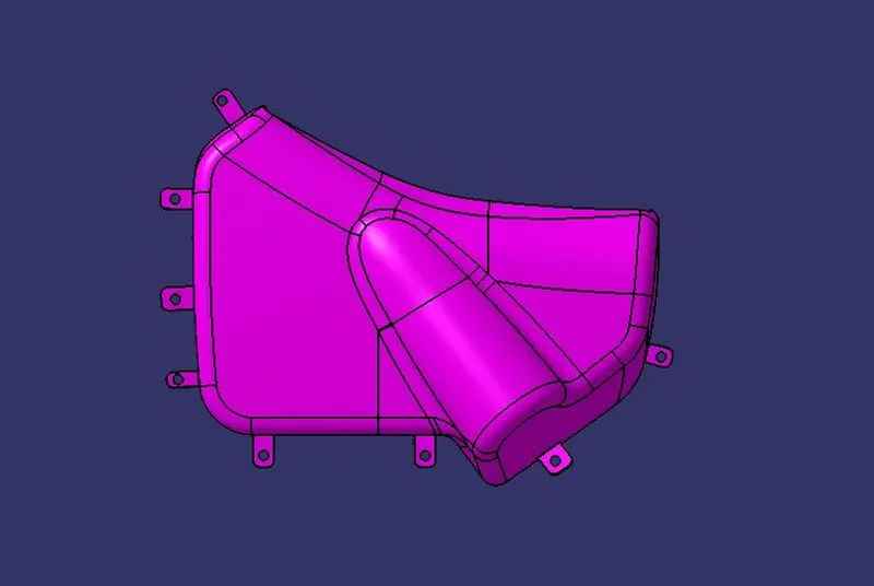
Top View:
Part 5 - Push Pin:
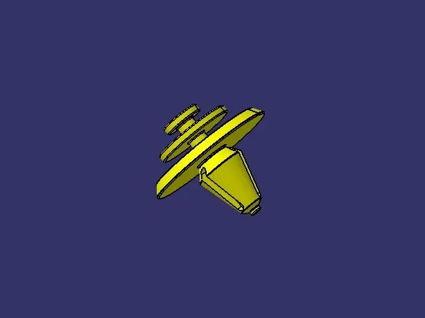
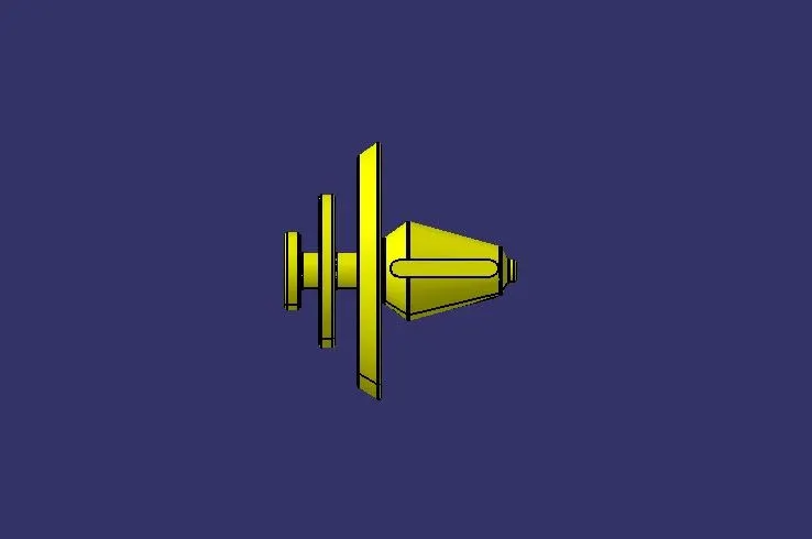
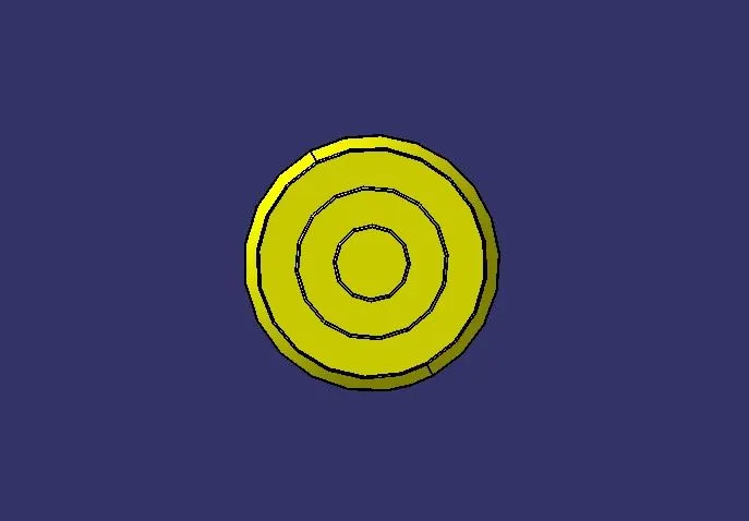
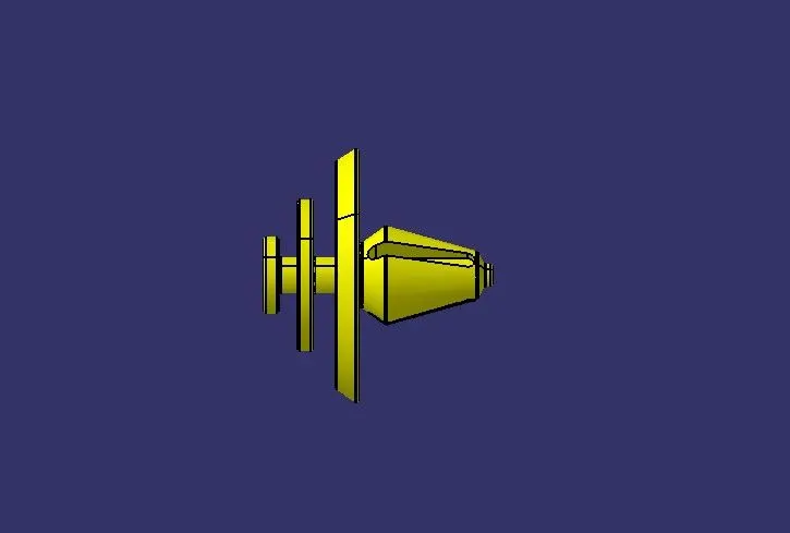
The push pin was provided as a part file. there was no design needed in it.
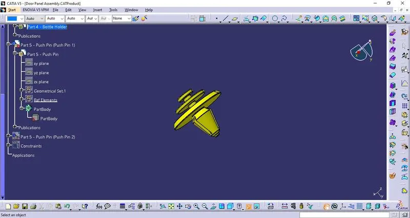
Component - Orientation Views:
Isometric View:
Front View:
Side View:
Top View:
ASSEMBLY:
Part 0 - Skeleton Reference:
The Skeleton reference part was created to define the central axis and planes of the assembly.
Constraints:
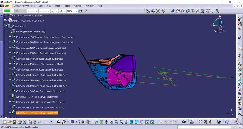
The components are constrained using different constraint commands to arrest the degrees of freedom except ones allowed in the constrained movement of the assembly.
- Constraint 1 - Fix
All degree of freedom of the Skeleton Reference Part is arrested using the Fix command.
- Constraint 2 - Coincide
The ZX Plane of the Skeleton Reference coincided with the ZX Plane of the Lower Substrate.
- Constraint 3 - Coincide
The YZ Plane of the Skeleton Reference coincided with the YZ Plane of the Lower Substrate.
- Constraint 4 - Coincide
The ZX Plane of the Map pocket coincided with the ZX Plane of the Lower Substrate.
- Constraint 5 - Coincide
The YZ Plane of the Map pocket coincided with the YZ Plane of the Lower Substrate.
- Constraint 6 - Coincide
The ZX Plane of the Arm Rest coincided with the ZX Plane of the Lower Substrate.
- Constraint 7 - Coincide
The YZ Plane of the Arm Rest coincided with the YZ Plane of the Lower Substrate.
- Constraint 8 - Coincide
The XY Plane of the Arm Rest coincided with the XY Plane of the Lower Substrate.
- Constraint 9 - Coincide
The ZX Plane of the Bottle Holder coincided with the ZX Plane of the Lower Substrate.
- Constraint 10 - Coincide
The XY Plane of the Bottle Holder coincided with the XY Plane of the Lower Substrate.
- Constraint 11 - Coincide
The XY Plane of the Bottle Holder coincided with the XY Plane of the Lower Substrate.
- Constraint 12 - Coincide
The Reference Axis from Push Pin 1 coincided with the Axis of the dog House in the lower Substrate.
- Constraint 13 - Offset
The Xy plane of Push Pin 1 is offset for -678.863mm with the ZX Plane of Lower Substrate.
- Constraint 14 - Coincide
The Reference Axis from Push Pin 2 coincided with the Axis of the dog House in the lower Substrate.
- Constraint 15 - Coincide
A reference line from Push Pin 2 coincided with the reference axis from the Lower Substrate.
- Constraint 16 - Offset
The Xy plane of Push Pin 1 is offset for -705.133mm with the ZX Plane of Lower Substrate.
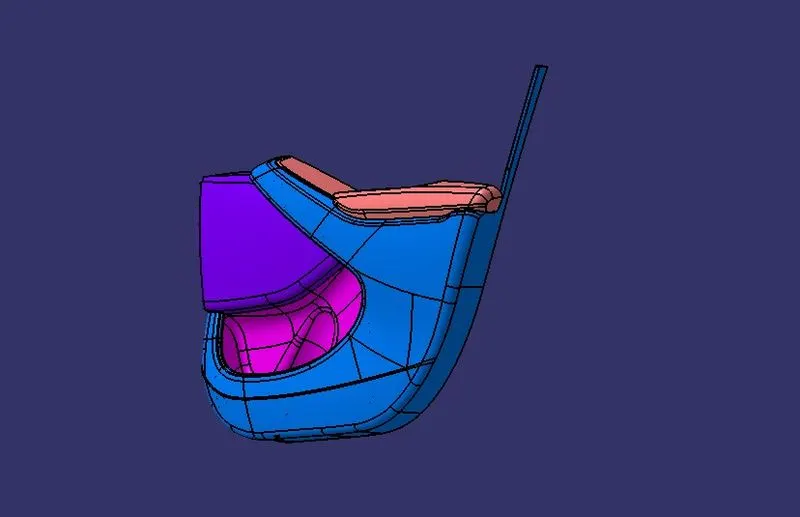
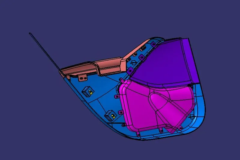
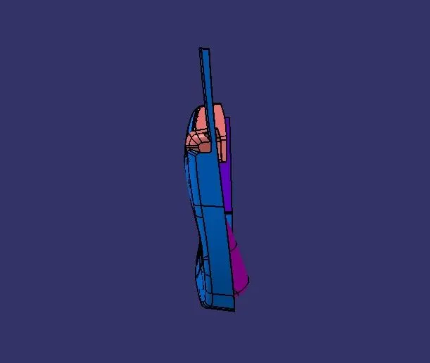
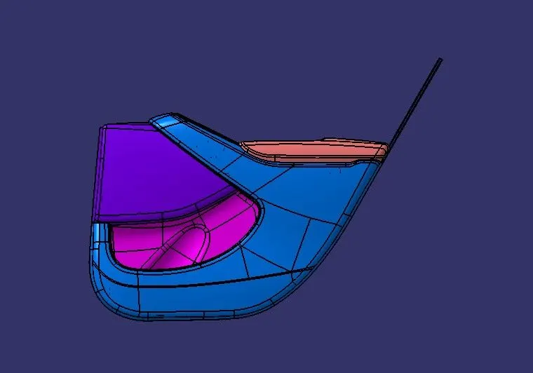
Assembled Product:
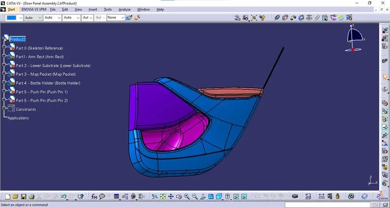
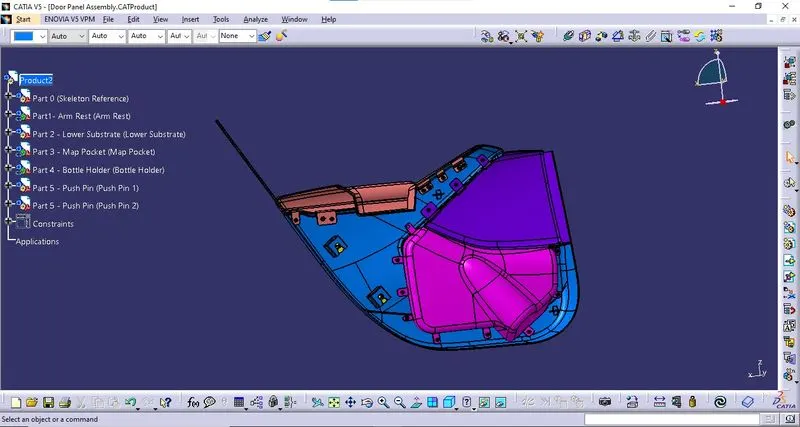
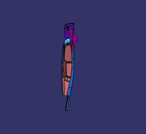
The assembled product is shown below.
Product - Orientation Views:
Isometric View:
Front View:
Left View:
Right View:
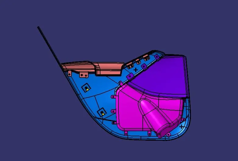
Top View:
ATTACHMENT:
The following files are attached as a single ZIP file.
- Door Panel assembly.CATProduct
- Part 0.CATPart (Skeleton Reference)
- Part 1.CATPart (Arm Rest)
- Part 2.CATPart (Lower Substrate)
- Part 3.CATPart (Map Pocket)
- Part 4.CATPart (Bottle Holder)
- Part 5 - Push Pin.CATPart