Week 11 - Final project
REPORT
Aim:
- Development of a Door Trim panel
- Creation of CAD model considering following inputs as like in OEM and tier1 companies
- a) Class A surface
- b) Nominal thickness : Refer master sections
- c) Attachment strategy :
- Find a attachment strategy for the door panel complete work.
- Use Push pin with Dog house for Lower substrate – Door panel attachment
- Use heat stakes for part to part attachment.
Door Trim Panel
Door panels serve as an interface between the interior of the car and the inner workings of the door, and between vehicle occupants and the door. They are expected to meet a variety of design specifications regarding safety, aesthetics, and functionality. In addition, they are expected to continue the material theme of the dashboard and pillars while concealing intricate electrical and mechanical components for operating locks, windows, and other features.
Door Trim Parts
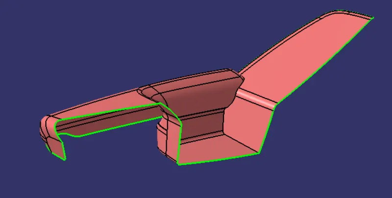
- Door armrest
- Bottle holder
- Map pocket
- Lower substrate
Inputs:
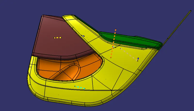
Class A Surface with Master sections
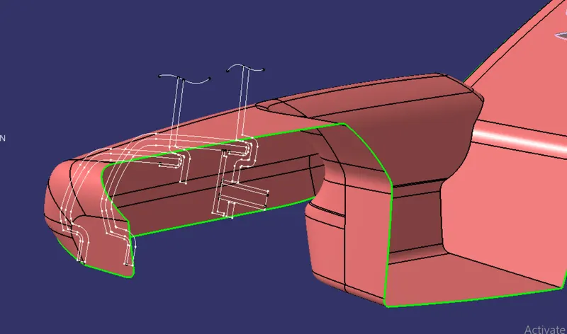
Door Armrest
Bottle Holder
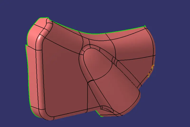
Map pocket
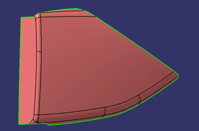
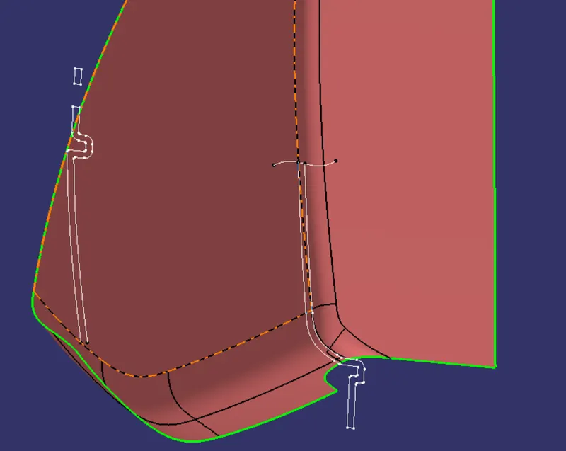
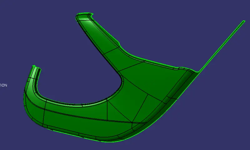
Lower Substrate
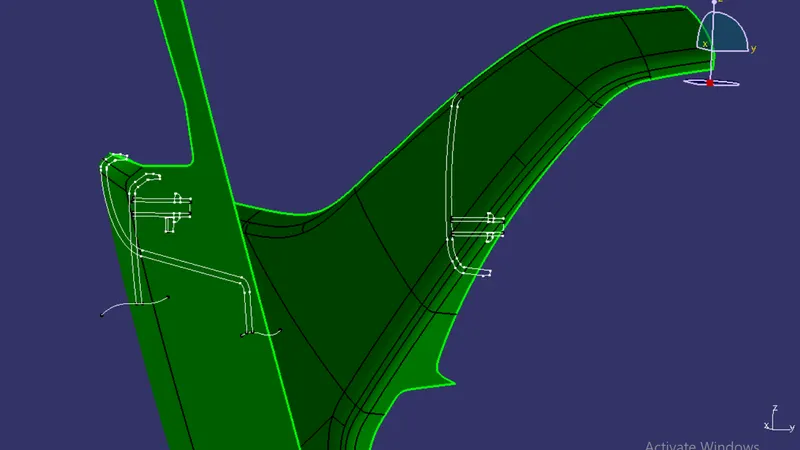
Tooling Axis
- Tooling axis indicates the direction through which the tooling (molding, core and cavity movement) is done.
- The axis should be created in such a way that all the parts of the body can be created through that axis.
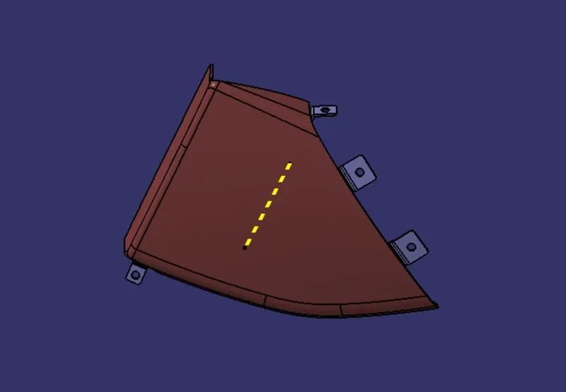
- For the given Class-A-Surface the tooling axis is in the direction normal to the largest plane.
- We can use the Compass from the draft analysis toolbar to move around and placing the compass on to the surfaces can show how much area is cleared in draft analysis by the line that is normal to that surface.
- By this method, the area on the surface will be extracted and the line normal to that surface will be the required Tooling Axis.
- It was also to be considered that the tooling axis should clear the B side feature as well.
- This formed line is the required Tooling Axis. Draft analysis and core-cavity design for the plastic part and B side features (Heati stakes) is done along this tooling axis.
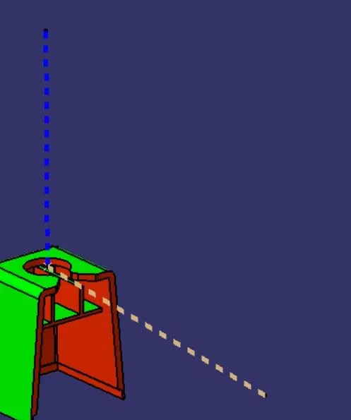
- For B side features like Dog houses additional tooling axis must be provided to design the inner geometry. This tooling axis is called Slider Axis.
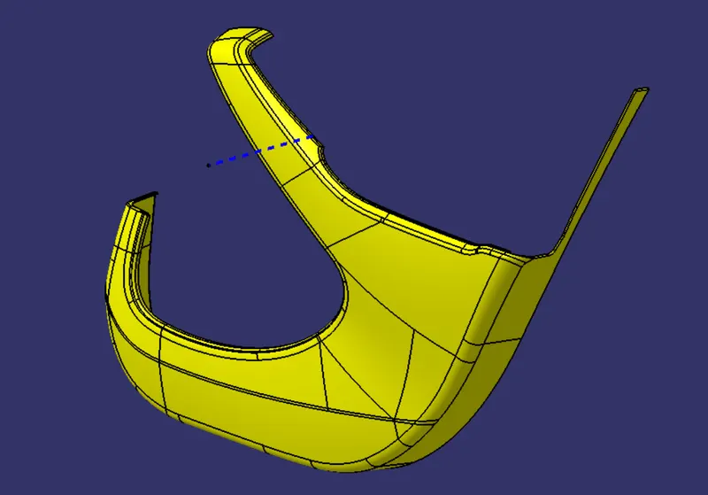
- For the given bodies slider axis is provided for door arm rest and lower substrate.
Tooling Axis for Various Parts
Door Arm Rest
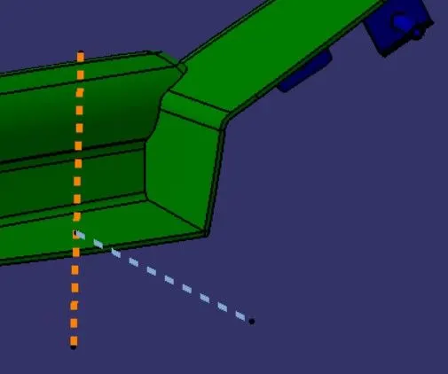
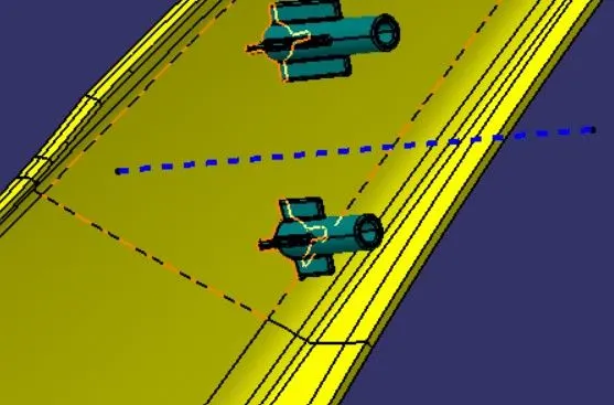
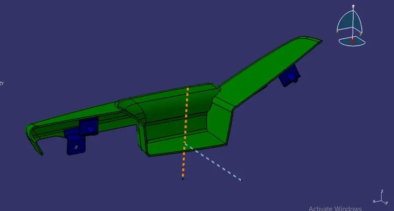
- The orange line shown above is the main tooling axis and the blue line is the slider axis.
Bottle Holder
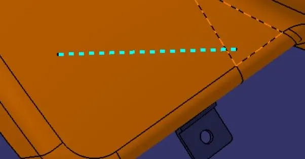
Map Pocket
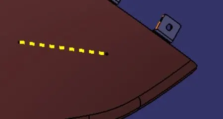
Lower Substrate
Dog House
Draft Analysis
- Draft allows a part to release from the mold. Draft is required on all parts in the direction of the mold movement in order to allow parts to release or eject from the mold properly.
- Draft is the angle in the part is tapered to allowed it to release. As the part cools it tends to shrink to the core side of the mode.
- The given Class-A-Surface is analyzed for draft angle.
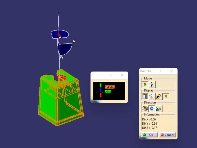
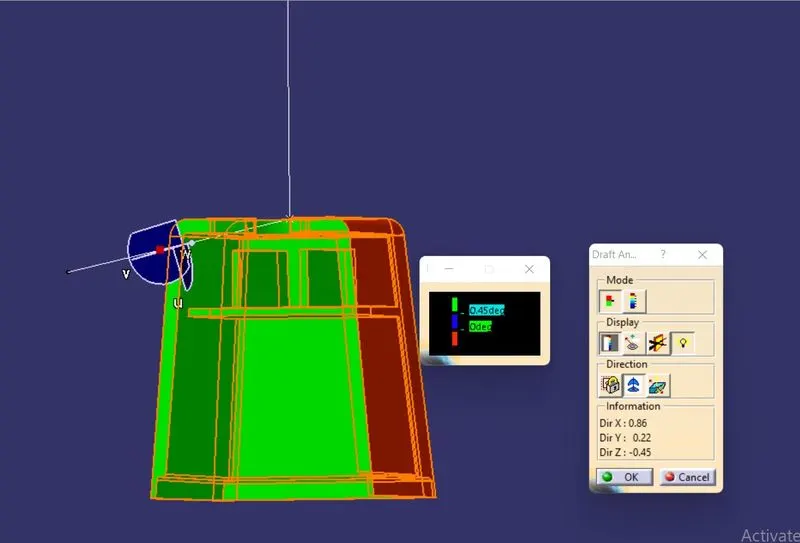
- The Draft Analysis Toolbar in CATIA V5 is used. After importing the Class-A-Surface the View Mode Customization is selected and in the custumization windows, in the shading section Material is selected.
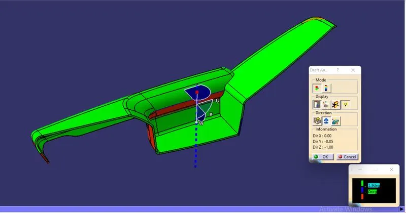
- After that the Draft Analysis Toolbar is selected and in the draft analysis window the Compass is selected and it is repositioned at top side of the Tool Axis.
- Then the surface is selected and the surface color is shown according to the draft given to it.
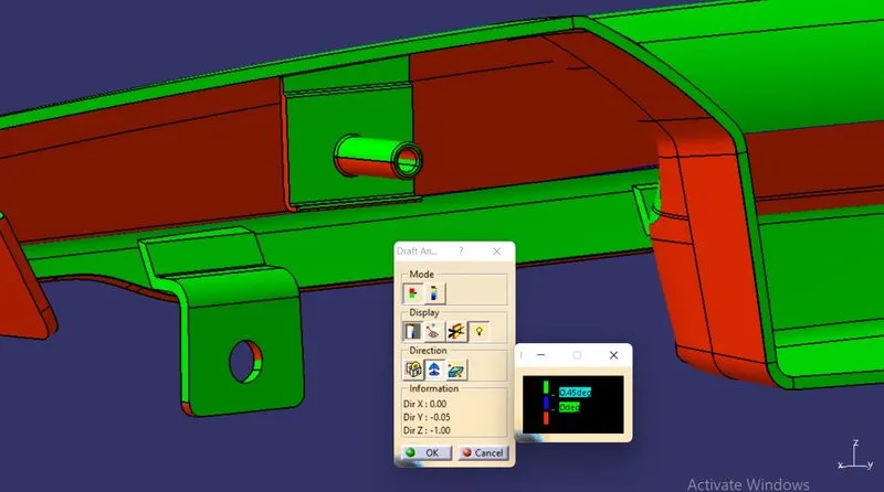
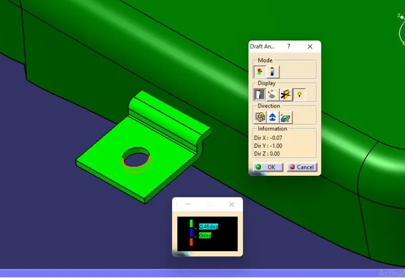
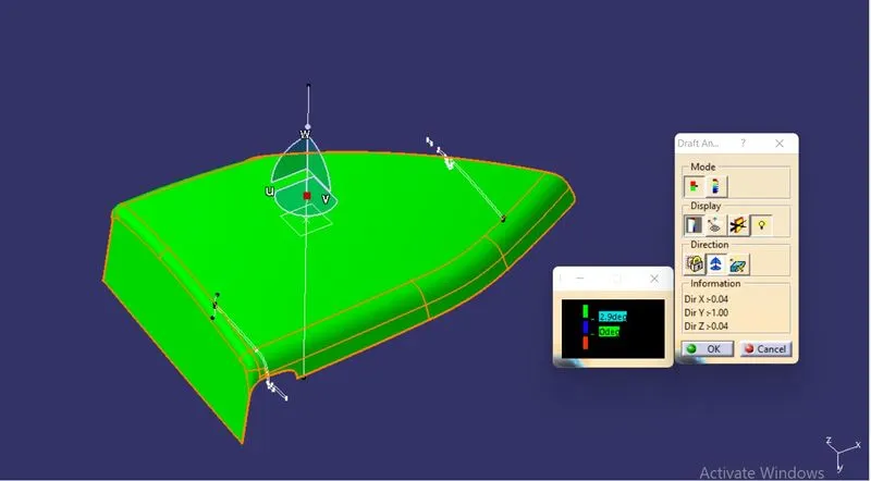
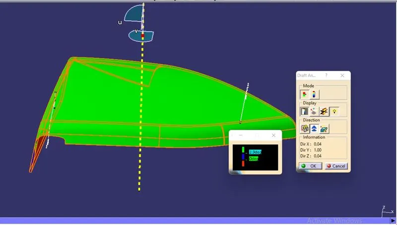
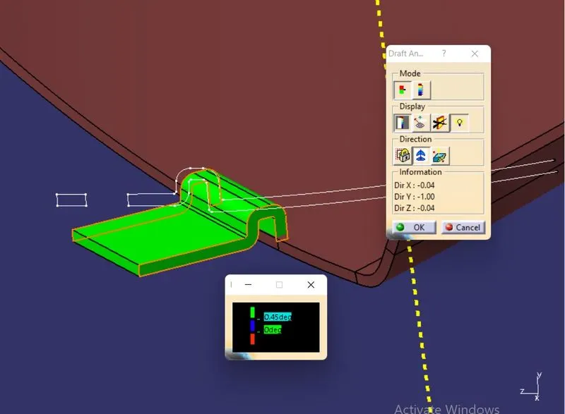
- For Draft angle above 2.9 degrees for part surfaces and 1.5 or 0.5 degrees for B side features the surface is colored Green, for Draft angle with 0 degrees the surface is colored Blue and for draft angle less than 0 degrees the surface is colored Red.
- In some areas of the given Class A the surface will have 0 or negative draft angle, such areas cannot be resolved and when final plastic body is created these patches with draft angle variations is also reflected on to the solid body as well.
Draft Analysis for Various Parts
1. Door Arm Rest
- Class A Surface
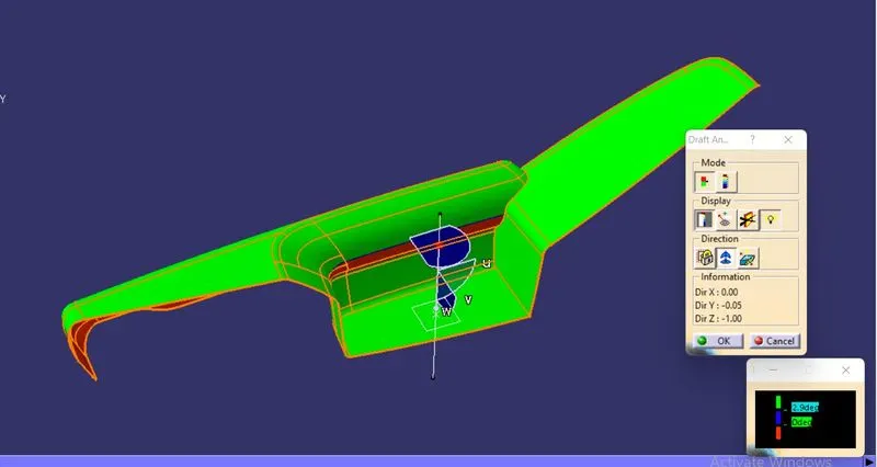
- Patches of Class A with 0 and negative draft angle
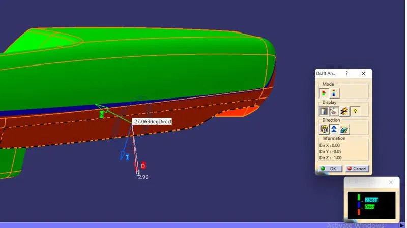
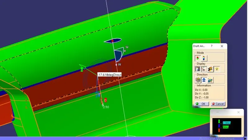
- These patches shows zero and negatice draft angle on the Class A surface which cant be resolved be changing the direction of tooling axis.
- So the solid body is created with this patches as well.
- Final Plastic Body
- B Side Feature (Flanges & Heat stakes)
2. Bottle Holder
- Class A Surface
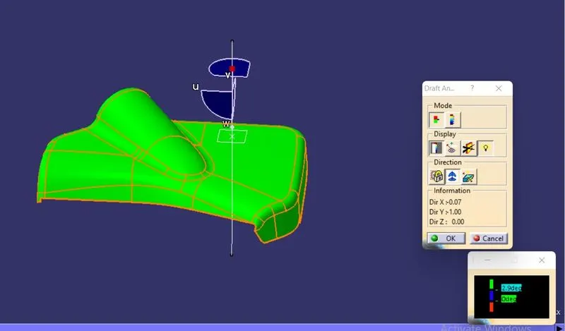
- Patches on Class A with negative and zero draft angle
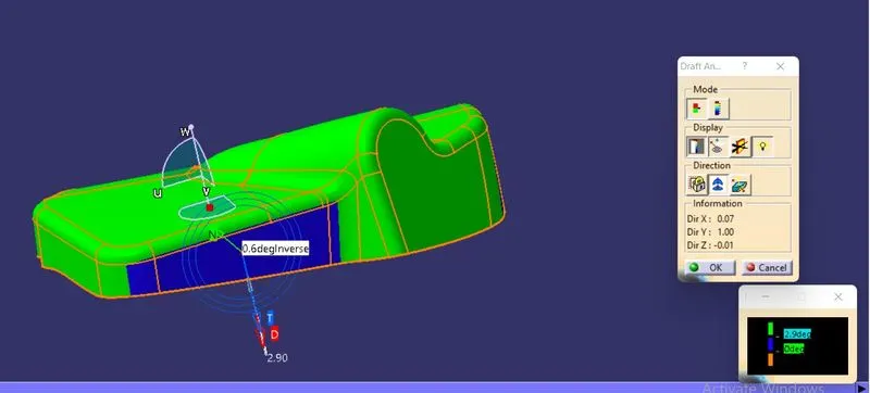
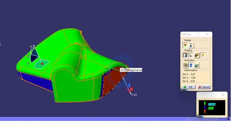
- Final Solid Part
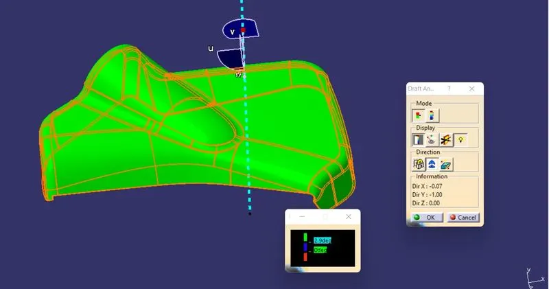
- Solid Part with same patch having neagative draft as Class A.
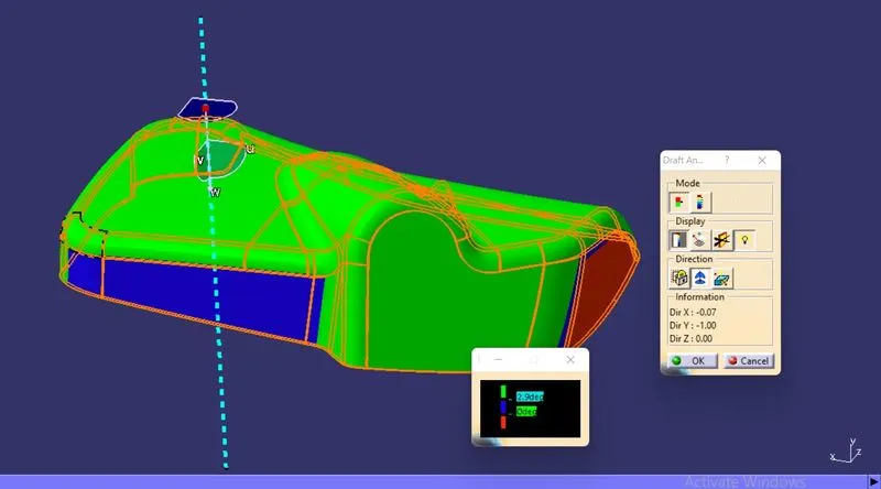
- B Side Feature - Flanges
3. Map Pocket
- Class A Surface
- Final Part Body
- B Side Feature - Flanges
4. Lower Substrate
- Class A Surface
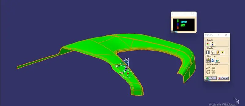
- Patches of negative or zero draft angle on Class A Surface
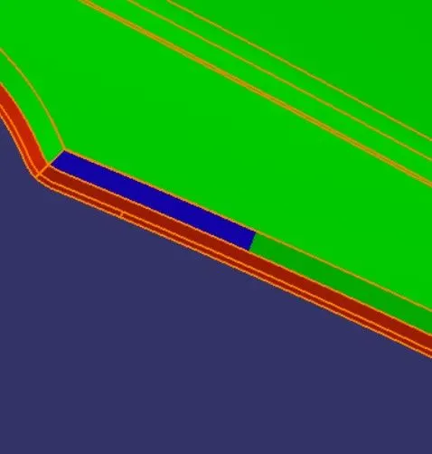
- Final Solid Part
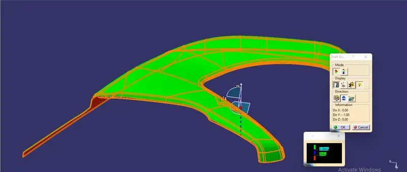
- B Side Feature - Heat Stakes
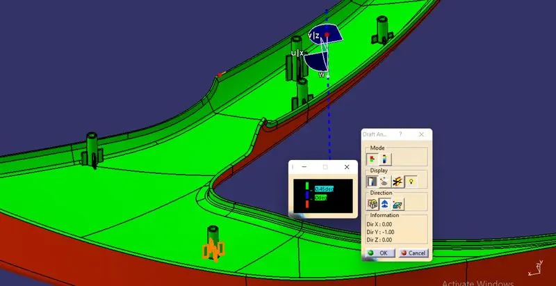
- Dog House
Procedure for Creation of Final Plastic Body
- The given Class A Surface is offsetted according to the master section thickness and surface coreections are made closing all patches and finaly creaing Class B surface.
- Now using sweep operations on Class A and Class C surafce is created which is then joined with class A.
- This joined Class A & C is trimmed with Class B to form the closed surface.
- This closed surface is made into a solid plastic part using Close Surface command in part workbench.
Final Plastic Body of Various Parts
1. Door Arm Rest
2. Bottle Holder
3. Map Pocket
4. Lower Substrate
Attachment Strategy
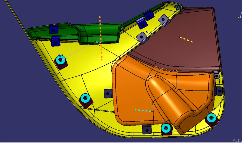
- The lower substare will act as a skeleton where all other parts will be attched.
- Door arm rest, map pocket and bottle holder will have flanges as B side features and lower substrate will be having heat stakes that perfectly fits in the flange holes of other parts.
- Four dog houses is also provide at four positions which will be assembled on to lower substrate.
- Push clip will then be assembled on to the top of the Dog House.
- The push clip will meet the counter part which will be a sheet metal.
B Side Features
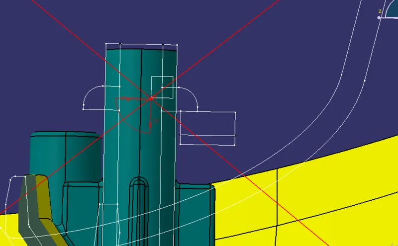
1.Heat Stakes
- Heat staking technology is quite simple in concept. Whenever two or more components need to be attached to one another, and at least one is made of a thermoplastic, a combination of heat and pressure can be used to reform the plastic to the many shapes or profiles to retain or join the parts together.
- This creates a solid, hardware-free bond that uses the plastic’s inherent strength to keep the finished assembly together.
- The main advantage to heat staking, when compared to fastener-based technologies, is that manufacturers can perform all heat staking in one machine cycle and motion versus individual motions required for each fastener. A secondary benefit is that the manufacturers do not need to change the base material – it can remain “AS-IS” while the plastic is heat staked to conform to its final dimensions.
- Heat staking technology, on the other hand, creates almost no mechanical stress because it operates through precise control and application of the temperature and pressure to cause the reforming of the plastic that it makes contact with.
Design Considerations
Heat Stakes Provided on the Lower Substrate
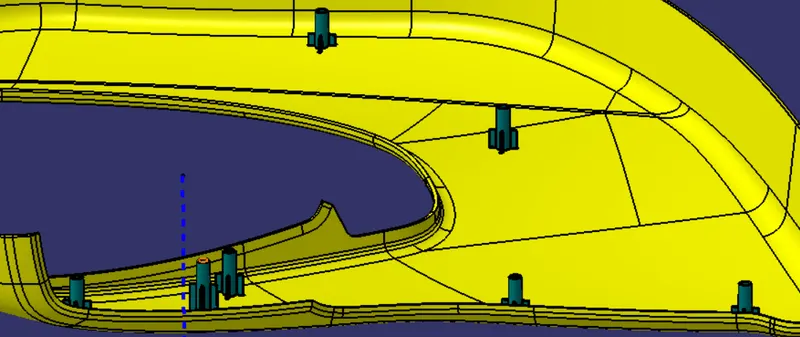
Heat Stakes Following the Master Section
2. Flanges
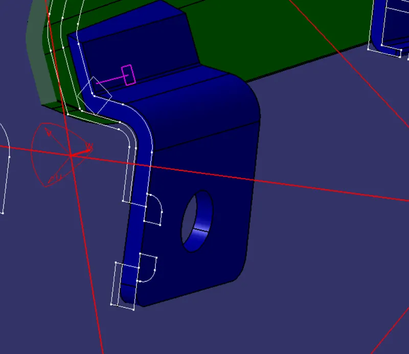
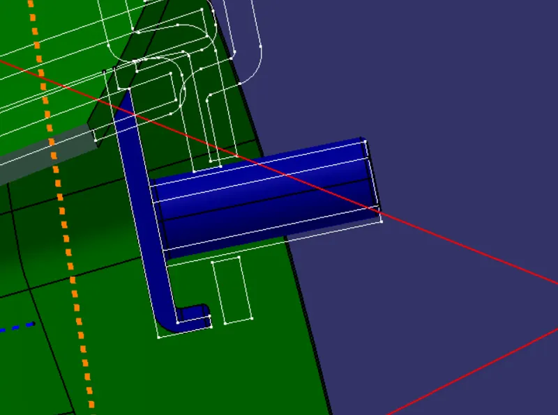
A flange is a protruded ridge, lip, or rim, either external or internal, that serves to increase strength (as the flange of an iron beam such as an I-Beam or a T-beam); for easy attachment/transfer of contact force with another object.
The flanges was created by extracting the required lines need for creating the geometry from the master section and formed the close body which is then paded to form the flanges.
Then they were translated to various positions.
Flanges Following Master Section
3. Dog House
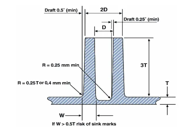
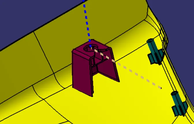
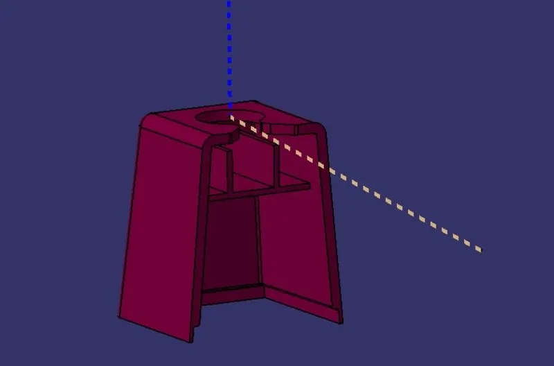
Dog house is an engineering feature used in the plastic trim design. Dog houses are used as supporting feature. Sometimes other engineering features like snaps; locators etc. are mounded on them to increase their strength. Dog houses are subjected to draft analysis to prevent breakage of the component during ejection from the mould cavity. Dog house and other engineering components are built on B-surface.
Design Considerations
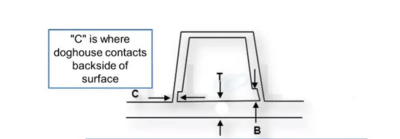
- Dog House lower wall thickness C should be 40% or less than main wall thickness.
- Height B should be between 3mm to 6mm.
- Outer walls draft angle is 1.5 degrees.
- Inner walls draft angle is 0.5 degrees.
- General fillet radius of the inner wall edges are 1mm and outer wall edges are 1mm + thickness.
- Note: the fillet radius may differ according to master sections.
Note: Here the dog house was inserted after remastering the provided dump solid.
Dog House assembled on the Lower Substrate
4. Push Clip
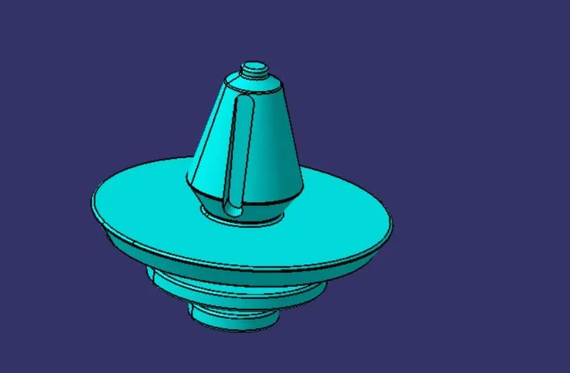
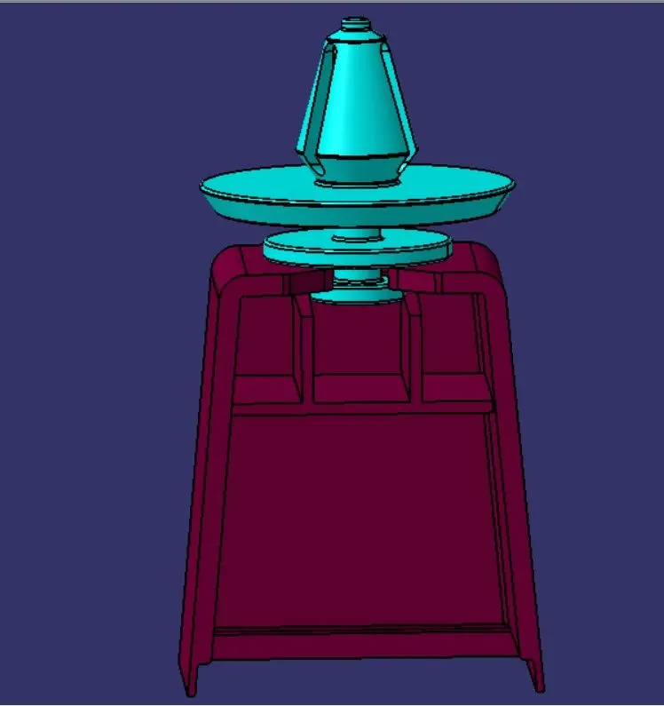
Pushpin is a type of plastic fastener whose sole purpose is to join two components, they are designed so that they can be easily attached and removed whenever needed and to make them not visible on the class A surface internal Dog house is provided for rigidity and distance to maintain the class A aesthetic to the customer and create installation and removal easy.
Here the push clip was provided and which is assembled on top of the dog house.
Push Clip Assembled on top of a Dog House
Final Door Trim with B side features in Various Orientations