Design of Arm Rest
DESIGN OF CLASS B, CLASS C AND CLOSED BODY OF ARM REST, LOWER SUBSTRATE AND MAP POCKET OF A FRONT DOOR PANEL AND PLANNING A STRATERGY FOR PLACING THE ATTACHMENT FEATURES AT REQUIRED POSITION USING CATIA V5
AIM
The aim of the project is to design the class B and class C surfaces of Arm rest, Lower Substrate and Map pocket of a Front Door Panel and then generate closed surfaces by combining them together to form a closed solid body to manufacture the components following industry standards. Attachment features are also mounted on the class B side of the components to attach the components with each other and avoid the manufacturing defects.
INTRODUCTION
The different components in this project are designed following the standards followed by the industry to manufacture the component by using injection moulding technique.
The steps followed to make the components mentioned below are:
1. Arm Rest
2. Lower Substrate
3. Map Pocket
1. Importing the class A surfaces of all the components from the OEM.
2. Determining the tooling axis of each component.
3. Performing draft analysis on each component.
4. Desiginng class B surface for each component.
5. Designing class C surface of each component.
6. Creating a closed surface by combining the class A, class B and class C surfaces and then converting it into closed body.
7. Designing attachment features like heat stakes, Dog house, push pins to the class B side of the component wherever it is required.
8. Determining the tooling axis of the Dog house for safely producing the feature.
9. Performing the draft analysis for each Dog house.
10. Designing push pins on top of each dog house for further attaching the components to the Sheet Metal.
PROCEDURE:
1. The class A surfaces provided by the OEM
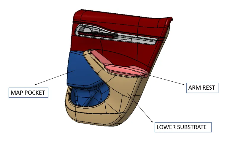
The first step in the project is to import the class A surfaces of the different components on the front door panel. Below image shows the imported class A surfaces
2. ARM REST
The Arm rest is the component which is used for the placing the hand of the person on the side of the doors.
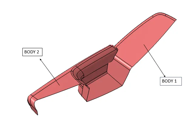
The arm rest in this project was divided into 2 bodies to make the component in the accurate manner. The below image shows the different bodies of class A surfaces of the arm rest
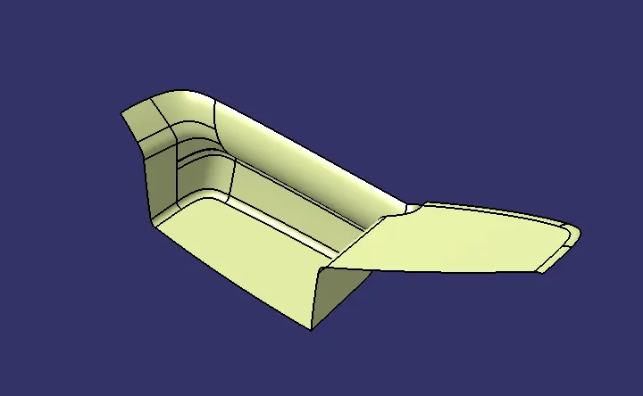
The class A surface of the 1st body of arm rest is extracted from the arm rest assembly using the multiple extract feature and then flanges were attached to the required position to attach the body at the correct position
Determining the tooling axis
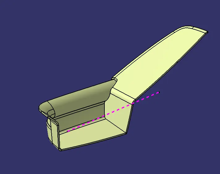
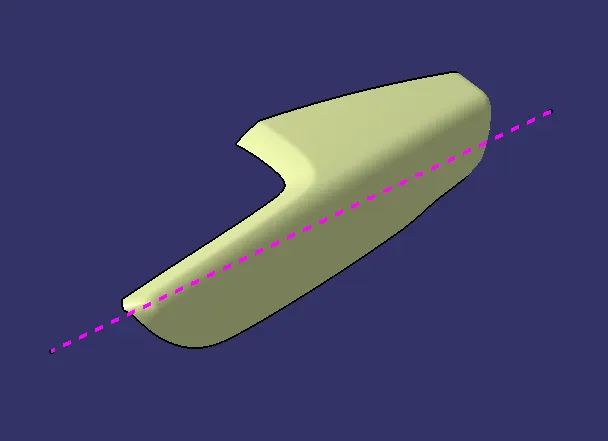
Tooling axis plays an important part for the safe removal of the component from the mould. It is the line along which the molten material is poured inside the cavity for manufacturing the component. The below images shows the tooling axis for the body.
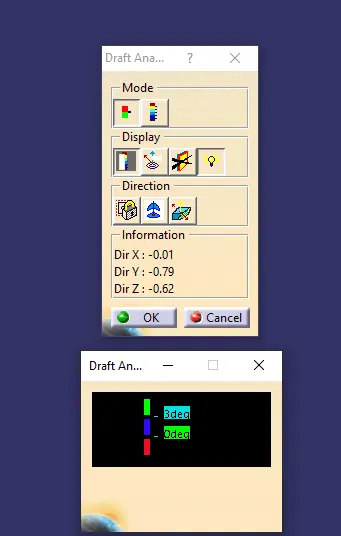
Draft Analysis
The draft analysis on the class A surface is done to check whether the tooling axis is in correct position 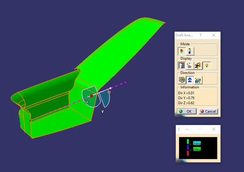
From the above image we can observe that the tooling axis is positioned correctly and the component can be tooled along the tooling axis safely.
Designing class B and Class C surfaces
The class B surface for the above the body is created by offsetting the whole body below the class A surface at a distance of 2.5 mm which was determined by the master section provided by the OEM.
The next step is to build the class C surface by taking the reference from the boundary of the class A surface along the tooling axis by giving a 3 degree draft wherever it is required.
The class A, class B and class C surfaces are then joined together by using the trim and join features and it is ensured that it forms a closed body. The below image shows the closed surface
It is double checked whether the component is completely closed by using the boundary feature and when it ensured that it is completely closed it is converted into a solid body by using the closed surface feature in the part work bench.
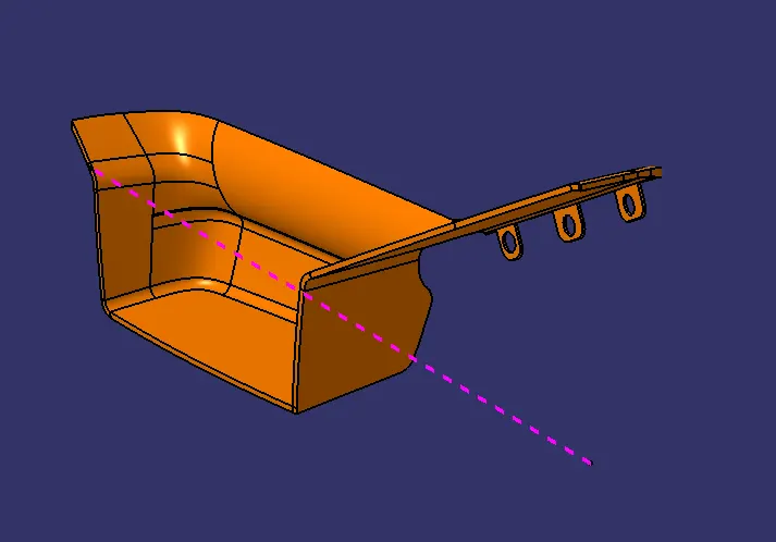
Attachment feature on Arm rest body 1
Heat stakes are made on the class B side of the component to attach it with the arm rest 2nd body. A draft of 0.5 degrees is given on the faces of the heat stakes to make it manufacturable safely.
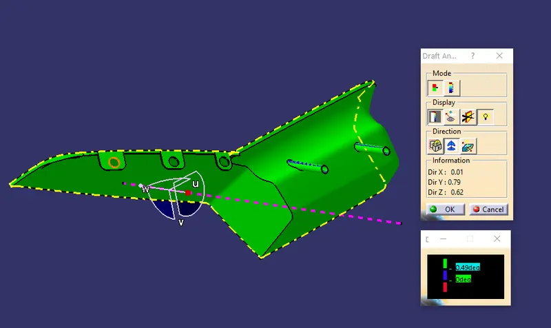
From the above draft analysis we can observe that the component and the attachment features can be manufactured easily along the main tooling axis.
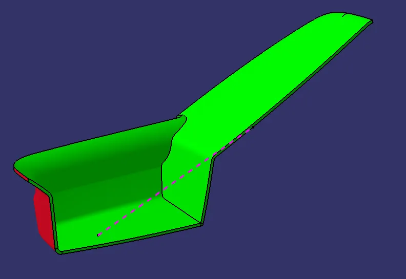
Draft Analysis on the closed body
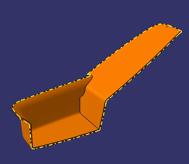
Arm Rest body 1 parting line
The parting line is the line present between the parting surface and the component, it separated the core and the cavity in an mould.
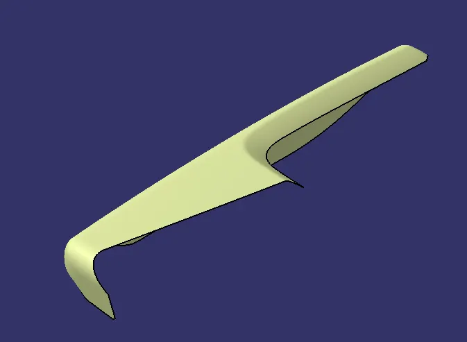
ARM REST BODY 2
The second body of arm rest is also made by following the same procedure above with the reference of the class A surface for the second body.
Class A surface
Determining the tooling axis for the above body
Draft analysis
The Draft analysis is performed on the class A surface to ensure that the tooling axis is at correct position and the component can be tooled easily along the tooling axis direction
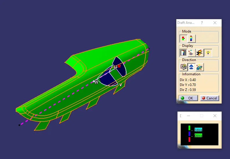
From the above analysis we can determine that the tooling axis is in correct direction and the component can be tooled along this direction.
Designing the class B and class C surfaces
The class B surface is designed below the class A surface of the body at a distance of 2.5 mm by using the offset feature.
The class C surface is made along the boundary of the class A surface.
After making the class B and class B surfaces, all of them are combined together to form a closed surface.
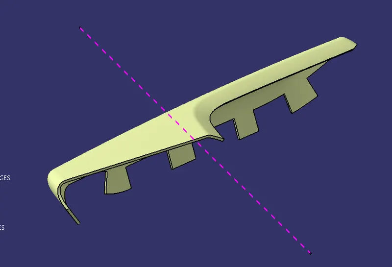
The above closed surfaces are converted into the closed body using the close surface feature in part work bench.
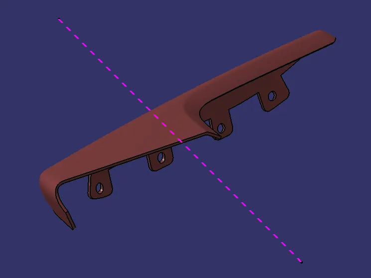
The draft analysis is performed on the closed body to check whether the component can be tooled along the tooling axis.
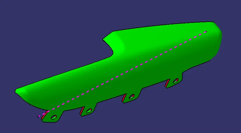
From the above analysis we can observe that the component can be manufactured from the body designed by the above method.
Arm rest body 2 parting line
The parting line is the line present between the parting surface and the component, it separated the core and the cavity in an mould.
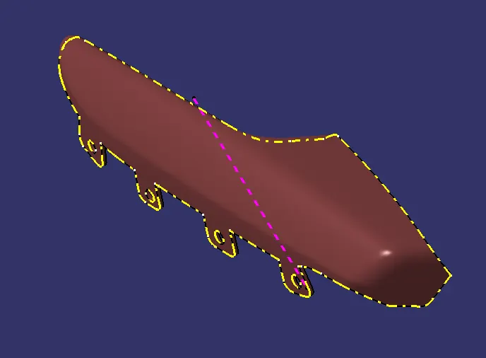
2. Lower Substrate
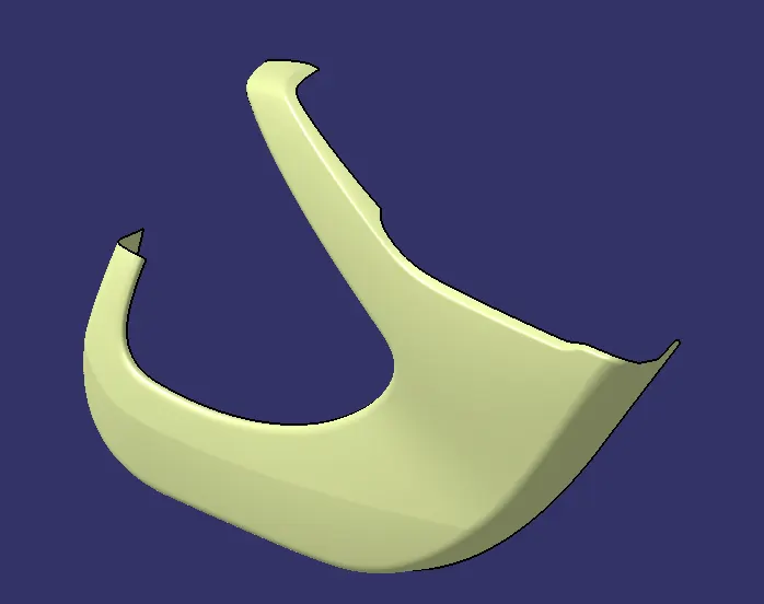
The Lower substrate is present at the bottom portion of the door panel.
The class A surface that was imported is shown below:
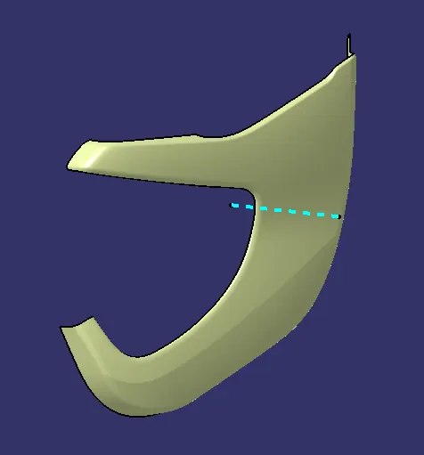
Determining the tooling axis for the above component
The tooling axis is made for the component by first creating a reference point and the generating the line and then giving accurate direction to the line.
The draft analysis is performed to align the tooling axis to the desired direction
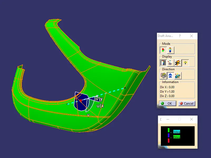
From the above image we can observe that the tooling axis is aligned at correct direction.
Designing the class B and class C surfaces
The class B surface for the lower substrate is made at a distance of 2.5 mm below the class A surface using the master section as reference by using offset feature.
The class C surface is made along the boundary of the class A surface along the tooling direction wherever required and providing a draft of 3 degrees for the easy removal of component from the mould.
The class A, class B and class C surfaces are joined together using the join and trim feature to form a closed surface body.
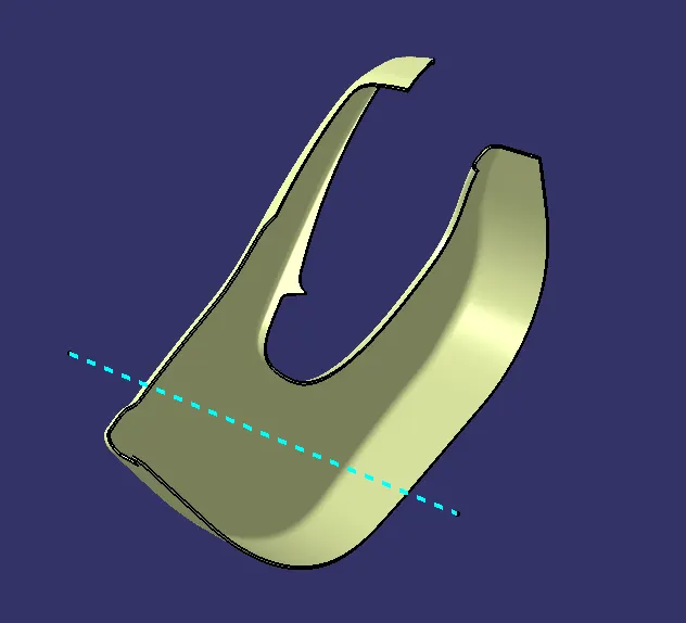
After this the closed surfaces are then converted into a closed solid body. Below image shows the closed solid body of the lower substrate.
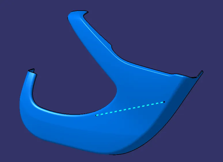
ATTACHMENT FEATURES ON LOWER SUBSTRATE
The different attachment features that are attached to lower substrate are:
1. Dog House
2. Heat Stakes
1. Dog House
The Dog house is made on the class B side of the lower substrate, it is mainly used to avoid sink marks and give strength to the component.
2. Heat Stakes
The heat stakes are mainly used to attach one component to another, this is done with the help of the flange on the other side of the component and then the heat stakes are heated to attach the component together.
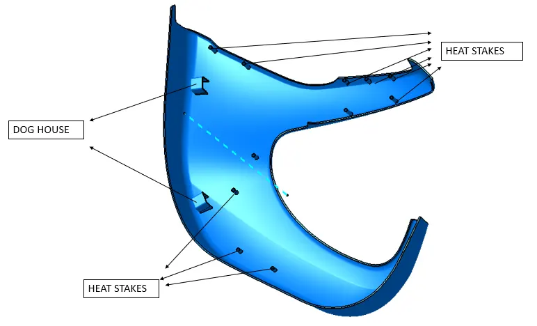
Separate slider tooling axis is made for the dog house to produce the feature safely along the slider tooling axis
A draft of 0.5 degrees is given on each face of the feature for easy manufacture of the dog house.
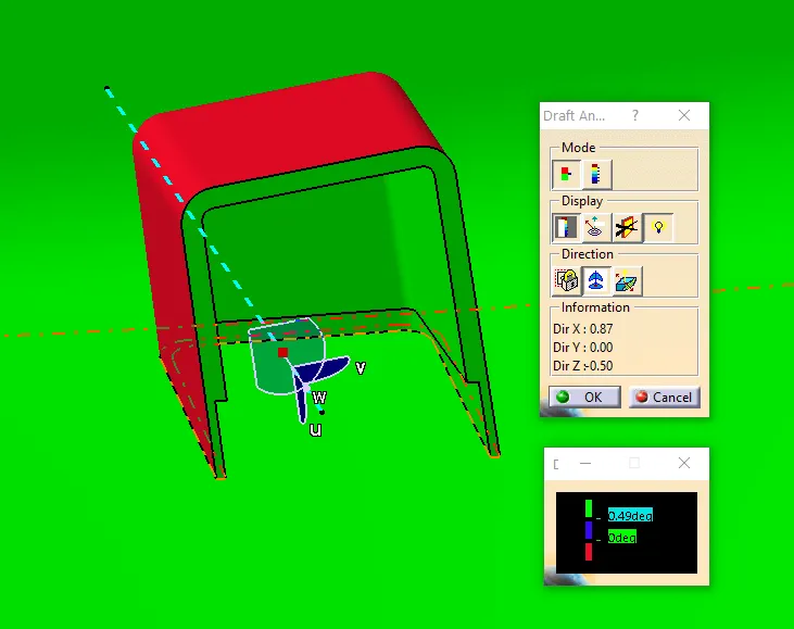
From the above draft analysis performed along the slider tooling axis for the dog house, we can observe that the dog house can easily be manufactured along the slider tooling axis and it is safe to tool along the tooling direction
The other dog house are also made following the same procedure and it is ensured that it is safe to be manufactured on the lower substrate.
The heat stakes are made on the class B side of the lower substrate by providing a draft of 0.5 degrees on the face of each heat stake for manufacturing the feature easily.
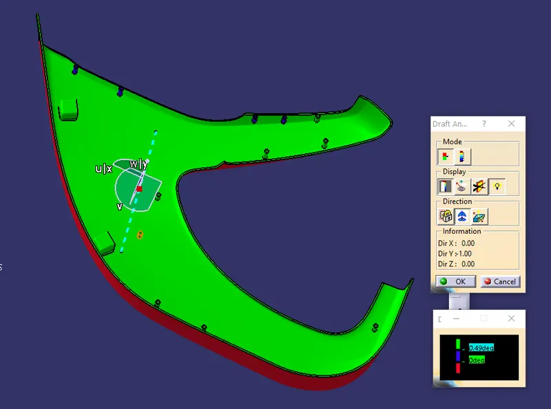
The draft analysis is performed on the class B side of the lower substrate by giving a 0.49 degree as draft angle, along with the attachment features to ensure that all the features can be manufactured easily along the main tooling axis of the lower substrate.
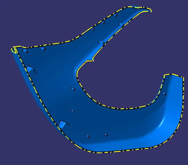
Lower Substrate parting line
The parting line is the line present between the parting surface and the component, it separated the core and the cavity in a mould.
3. MAP POCKET
The map pocket in this front door panel consists of a bottle holder as well.
It is divided into 2 bodies for making the component in an accurate manner
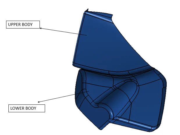
The class A surface of the upper body of map pocket is first imported into the work bench.
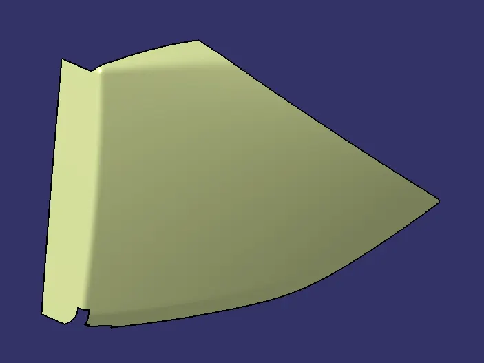
Determining the tooling axis and performing draft analysis
The tooling axis for the upper body of map pocket is made by taking a reference as a point and then making a reference line through the point
The line is then adjusted along a certain direction by using draft analysis feature to make the body clear in all sides along the tooling axis
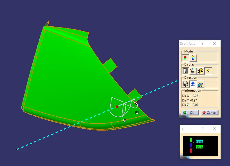
From he above draft analysis we can observe that the tooling axis is at correct direction and all the sides of the component can be tooled along the tooling axis for manufacturing the component safely.
Designing the class B and class C surfaces
The class B surface for the map pocket upper body is designed at a distance of 2.5 mm below the class B surface by using the offset feature.
The class C surface is made along the boundary of the class A surface along the tooling axis and a draft of 3 degree is given at required position to make the component easy for removal after the injection moulding process is over.
After designing class A, class B and class C surfaces together they are joined with each other using join and trim features and it is made sure that they form a closed surface body.
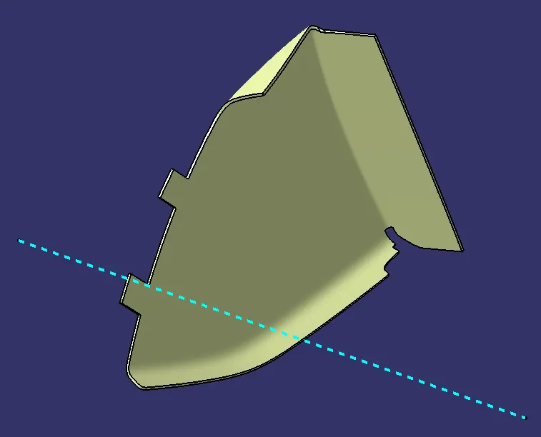
After closing all the sides together it is then converted into a solid body using the close surface feature to make it into closed solid body
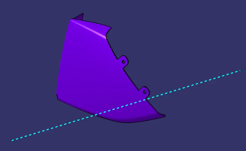
Attachment features on Map pocket upper body
Dog house is the attachment feature made on the upper body of map pocket to avoid sink marks and provide strength to the body.
A draft of 0.5 degrees is given on each face of the dog house for manufacturing the feature easily
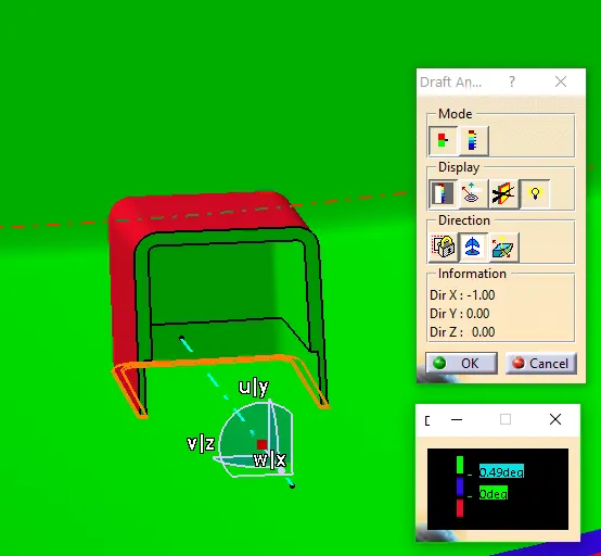
From the above draft analysis we can observe that the dog house designed is safe to manufacture along the slider tooling axis.
Heat stakes are made on the upper body of map pocket for attaching the upper body with the lower body of the map pocket.
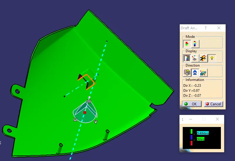
From the above draft analysis we can observe that the attachment features designed on this component are safe to manufacture along the main tooling axis.
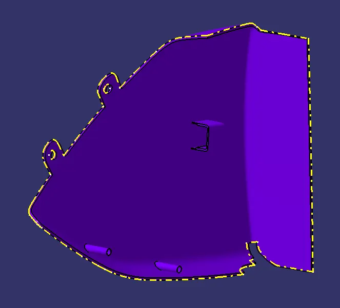
Map pocket upper body parting line
The parting line is the line present between the parting surface and the component, it separated the core and the cavity in a mould.
MAP POCKET LOWER BODY
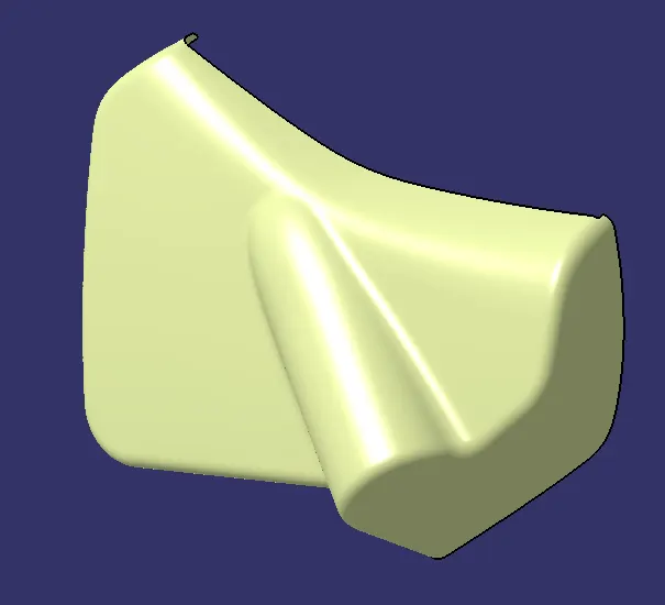
The class A surface for the lower body is first imported into the work bench
Determining the tooling axis and performing draft analysis
The tooling axis for the lower body of map pocket is designed by taking a reference point and then making a line through the point.
Draft analysis is performed for the class A surface to give the tooling axis certain direction to make the class A clear in all the sides.
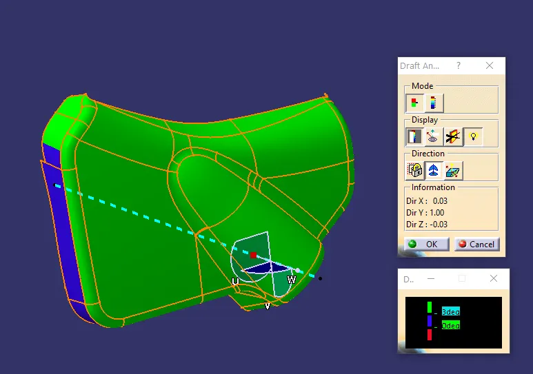
From the above draft analysis we can observe that the tooling axis is given correct direction and the component can be tooled along the tooling axis.
Designing the class B and class C surface
The class B surface for the map pocket lower body is designed at a distance of 2.5 mm below the class A surface by using the offset feature.
The class C surface is designed by taking the reference from the boundary of the class A surface and then giving a draft of 3 degree along the tooling axis for clearing the component from all sides.
After designing class A, class B and class C surfaces together they are joined with each other using join and trim features and it is made sure that they form a closed surface body.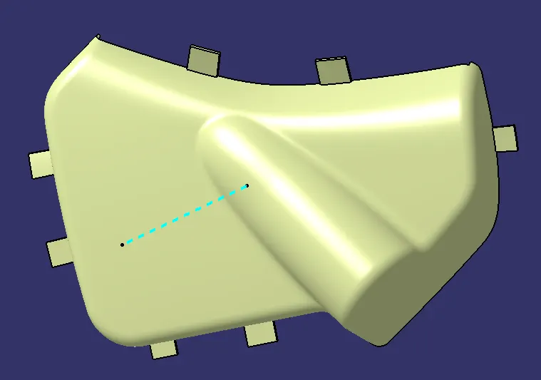
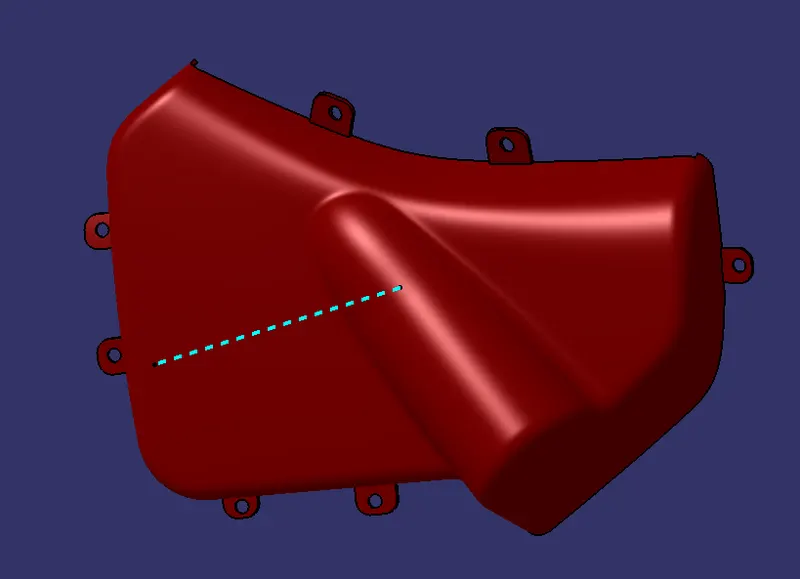
After ensuring that all the surfaces are closed from all the sides the closed surface body is converted into solid body using the close surface feature.
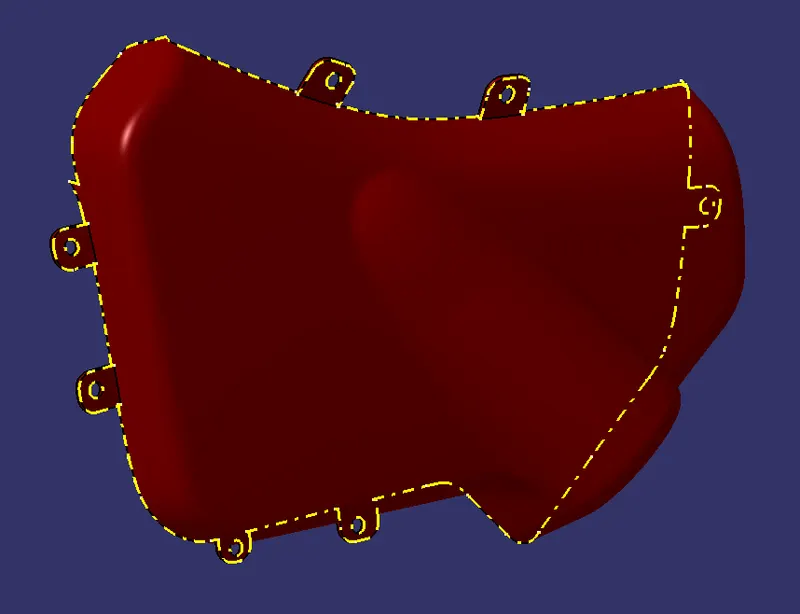
Parting line for Map pocket lower body
The parting line is the line present between the parting surface and the component, it separated the core and the cavity in a mould.
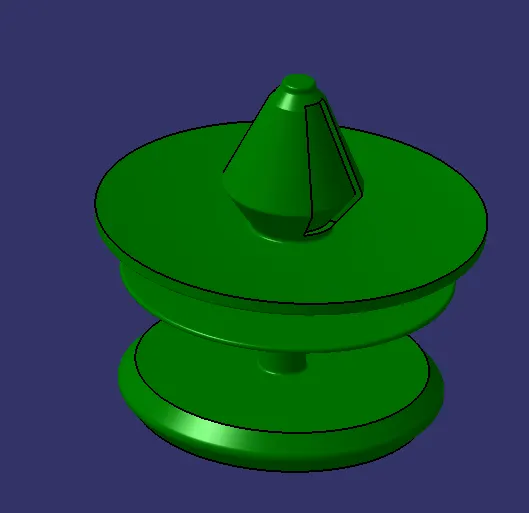
PUSH PINS
Push pins are designed in this project to attach the front panel with the sheet metal. It is designed on top of the dog houses.
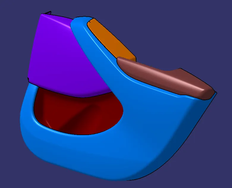
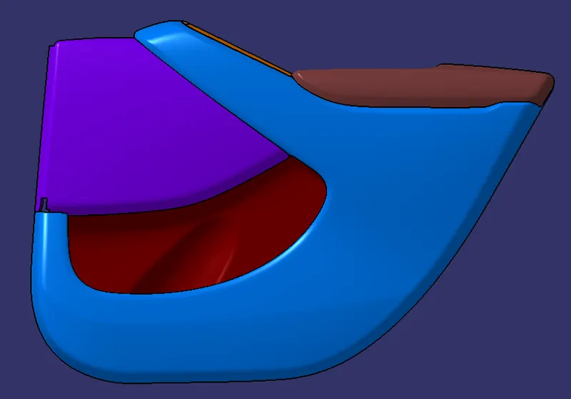
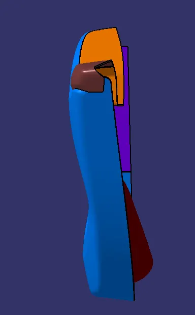
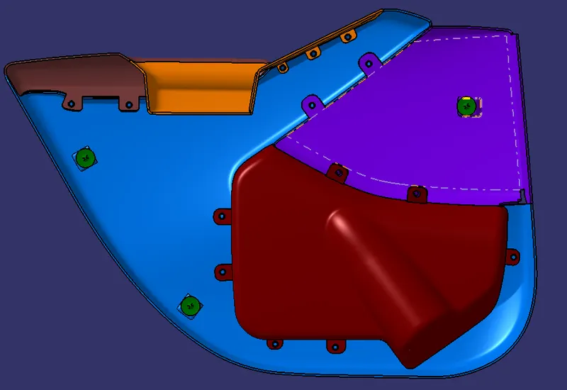
FINAL VIEWS OF ALL THE COMPONENTS AT THE SPECIFIED POSITION
1. Isometric View
2. Front view
3. Side view
4. Back view
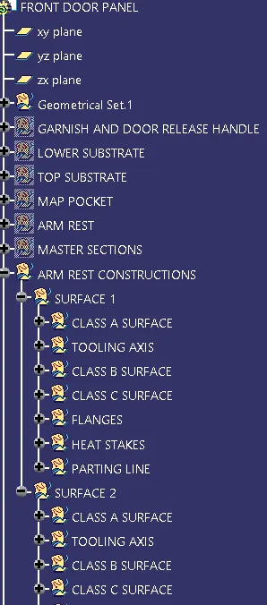
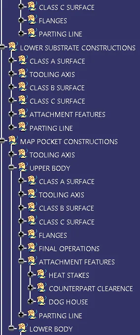
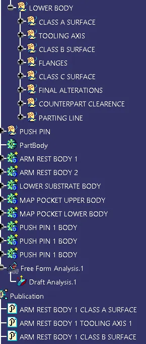
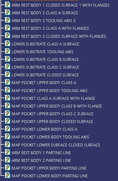
Tree Structure
The procedure used to make the component is mentioned in the structure shown below
CONCLUSION
1. All the class A, class B and class C surfaces were designed following the industry standards and converted into solid body.
2. Draft analysis on each component was performed and it was made sure that the component can be tooled along the tooling axis of each component.
3. Drafts were provided at required positions for manufacturing the component easily.
4. A proper strategy was implemented to place the attachment features like dog house and heat stake at required position to give the components strength and avoid sink marks.
5. Flanges were made at appropriate positions and heat stakes were aligned along it for attaching the component to each other.