Week 11 - Final project
Door Trim Panel Development
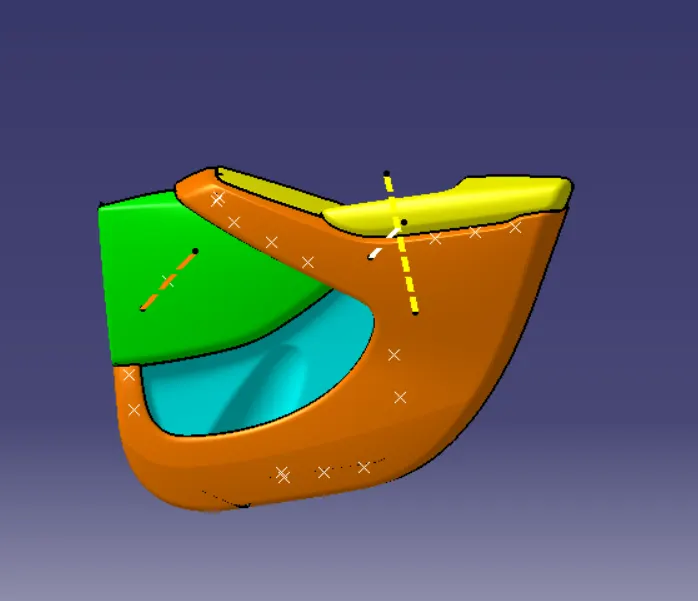
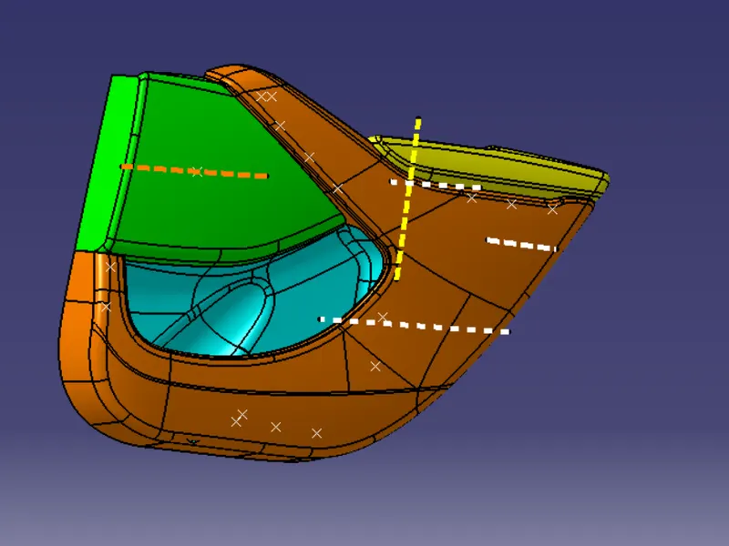
AIM:To develop the door trim panel for the given class A surface and mastersection and also create the necessary engineering B side features (Dog house , heat stakes with ribs)for the developed door trim panel to provide necessary fixation( using the puspin provided).
OBJECTIVE:
- To create thickened part using master section and class A surface for reference.
- To create the B-side features as per design guidelines in the industry and with master sections as reference.
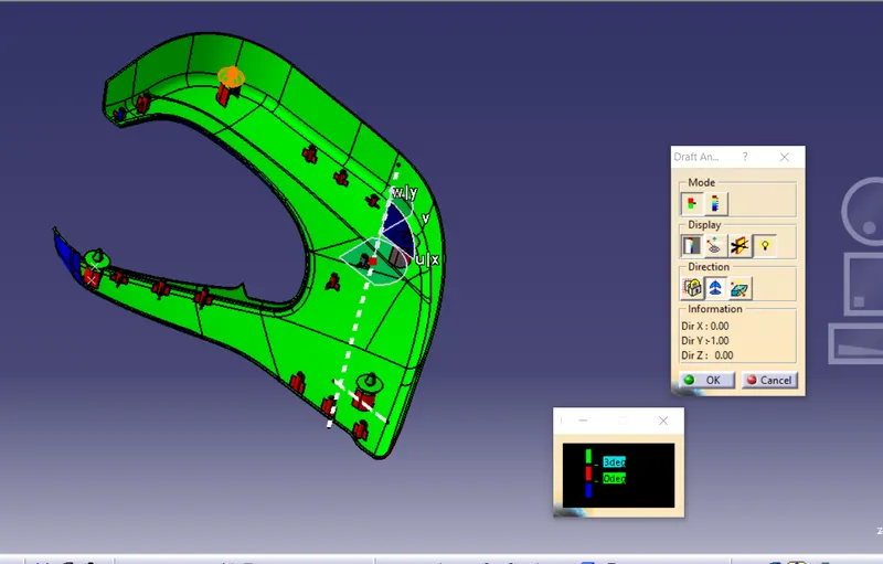
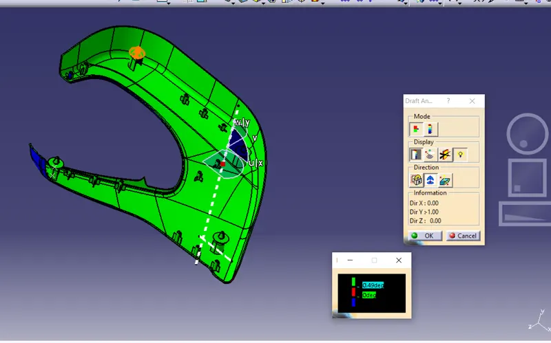
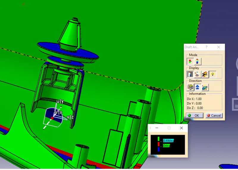
- To perform Draft analysis .
INTRODUCTION:
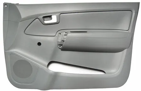
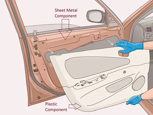
The door panel is the interface between the interior of the car door and the inner workings of the door. Generally the door panel is divided into parts for easy designability like Door arm rest, map pocket, lower substrate and bottle cap holder. These are one of the hardest requirement to design and develop among the interior parts of the car. This should be designed with appropriate design guidelines to withstand the load which is being being less than 2mm in thickness and also to protect the occupants during collisions.
PROCEDURE:
1) Creation of Tooling Axis:
Tooling Axis
- Checking the Connectivity of class A Surface,these can be done by using boundary otion or by join command if there are any gaps or openings they will be easily detected.
- Visually analyse the best possible tooling axis.
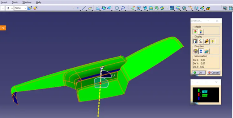
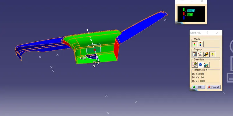
- upon analysing the method used is normal to surface method except the door arm rest, where you also need side core axis to clear the inner surface
- Here the bisecting method is not required because every side can be cleared throw the Z direction only easily.
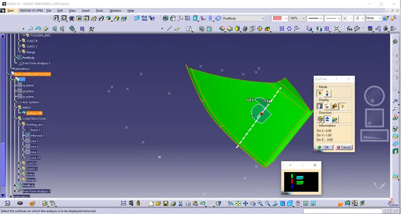
- The tooling axis is nothing but the direction in which the core and cavity open and close. The design engineer works to analyse the Class-A surface and find out the best possible tooling direction keeping in mind all the draft angles with respect to the tooling axis so that the component can be easily ejected from the moulds.
2) Performing the draft Analysis on the class A surface:
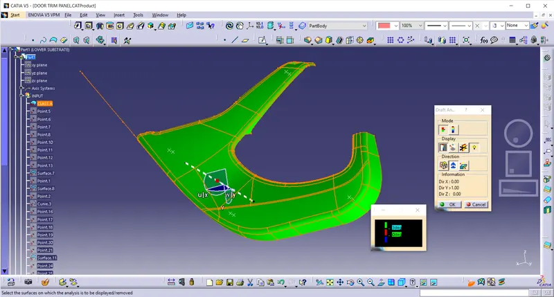
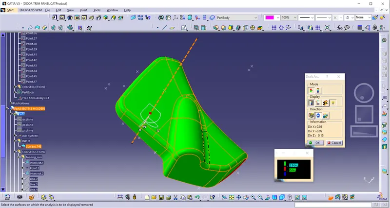
The below image shown is the draft analysis performed on the lower substrate and we clearly see the given class A surface has a nominal draft of minimum 3 degrees.
LOWER SUBSTRATE:
BOTTLECAP HOLDER:
MAP POCKET:
DOOR ARM REST
3) Class B surface Creation and Class C surface Creation:
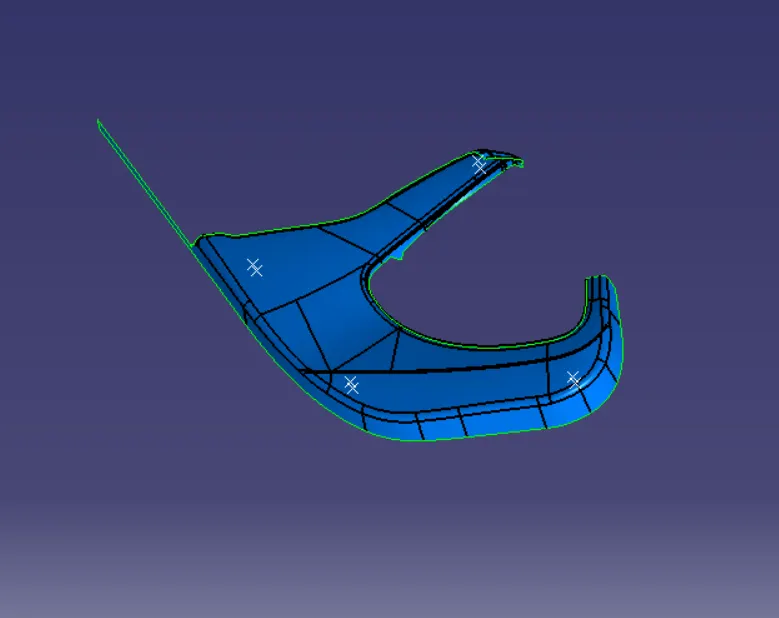
- Representing the internal or functional surfaces. This includes derived surfaces created by offset operations from class A surfaces in order to define the thickness of the material (2.5mm). In this file, it is important to link class B surfaces geometrically to enable an adaptation to class A surfaces automatically in case of styling change.
- B surface contains all the fillets and the edges which class A surface also contains.
a) Bottlecap holder
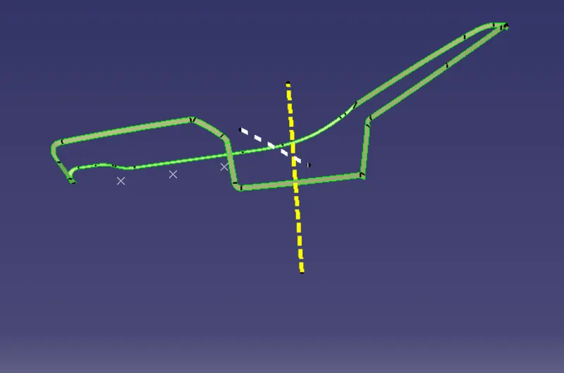
Class C Surface:
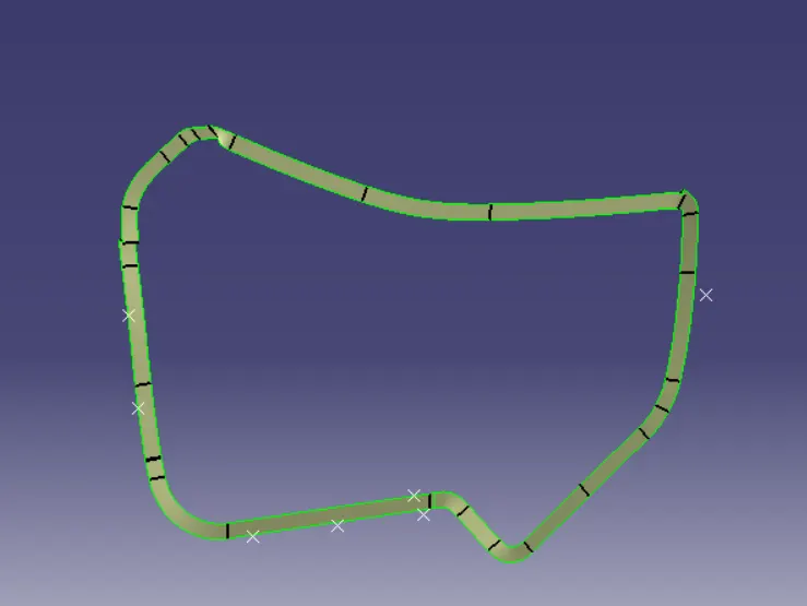
- Class C Surface is swept along the boundary of Class A at an angle to the CLASS A surface with respect to the tooling axis direction with a nominal draft angle of 3 degrees.
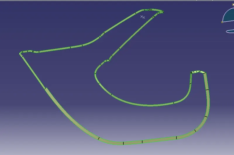
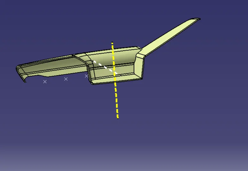
Joining CLASS A, B and C Surfaces to get Closed Surface
- After finishing all the 3 surfaces, join the class A and class C surfaces together using the Join command or trim command. Now, the joined surfaces are trimmed with the class B surface to form a closed surface.
- After joining the class A, B, C surfaces ensure that the surface has no gaps between them using the boundary command then use the closed surface in the part design to get the solid part.
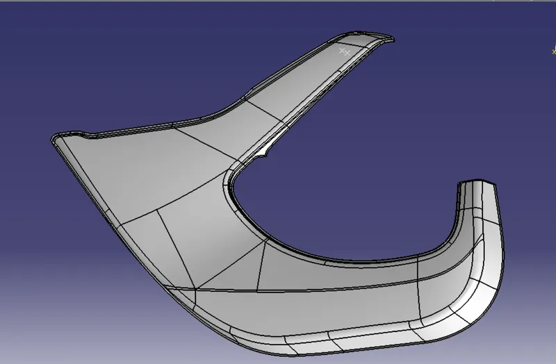
Similarly the same is followed creating the bottle cap holder, map pocket and door arm rest
b) Bottle cap Holder:
Class B Surface
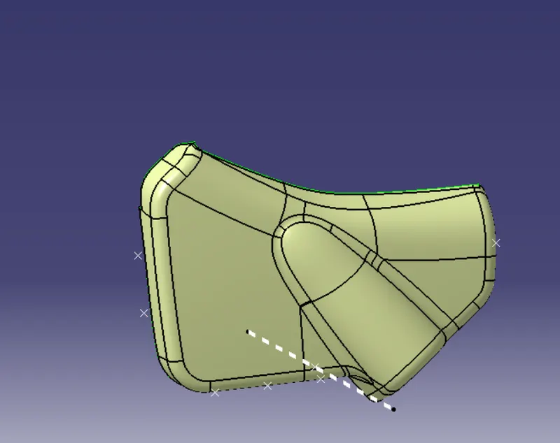
Class C surface:
Closed Surface:
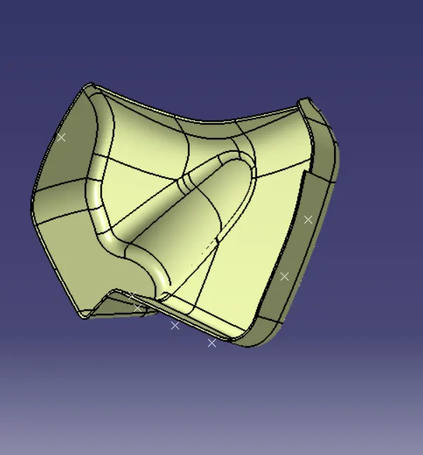
c) Map Pocket
Class B Surface:
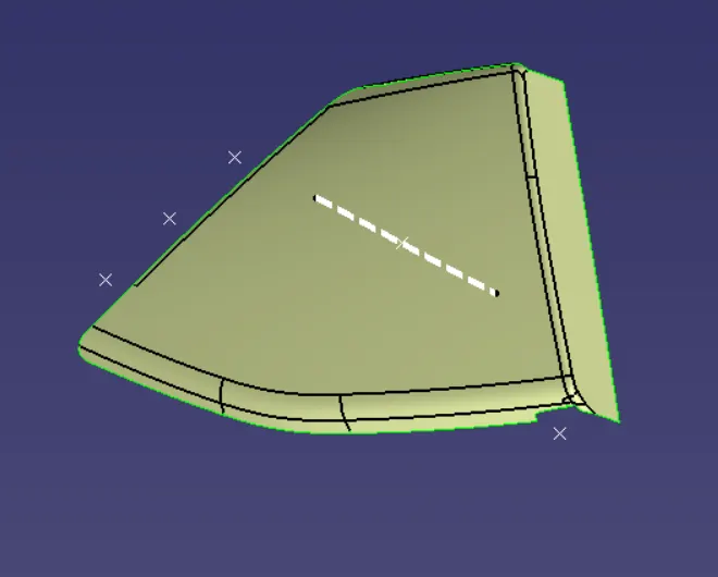
Class C Surface:
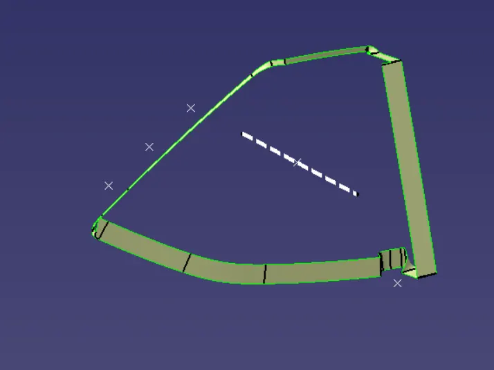
Closed Surface:
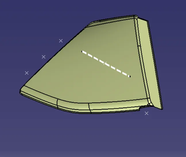
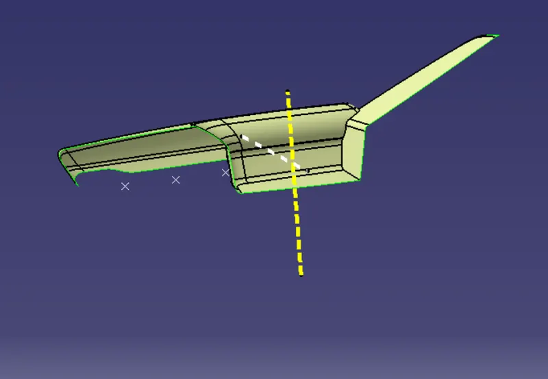
d) Door Arm Rest:
Class B Surface:
Class C Surface:
Closed Surface:
Creation of Engineering B Side Features:
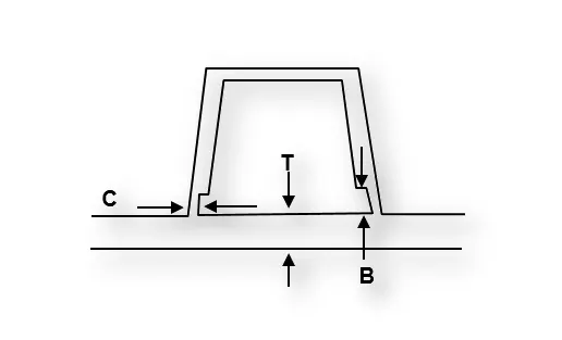
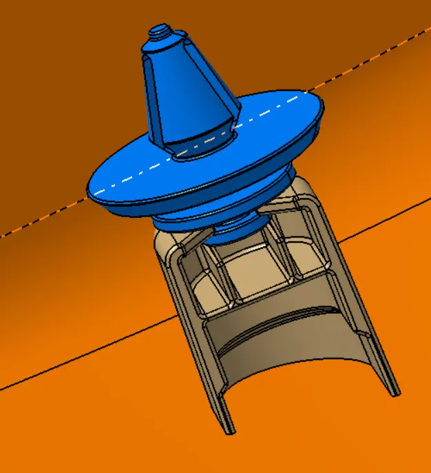
Dog House along With the given Pushpin:
DESIGN RULES FOR DOG HOUSE:
- Minimum height should not be Less than 6mm causes steel condition.
- 3:1 of steel width to height ratio. But 2:1 is preferred.
- Minimum width: 3:1 ratio of steel width to height. But 2:1 is preferred.
- Draft should be minimum 1.5degrees.
- Sink saver: height (C) = 40% of nominal thickness. Width (B) = 3.0mm-6.0mm.
- Optimal radius: 0.25mm
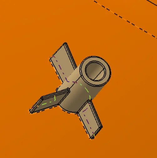
NOTE: The design rules for designing a 4-way locator pin are the same as that of ribs design rules.
Heat Stakes:
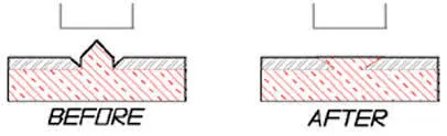
Heat Staking is a pulsed-heat process to join two or more parts out of which one of the part is atleast is made of plastic. The process is to deform the plastic material using heat and force at a set process time. The bond is made by partially de-forming the plastic part to fix the other.
Heat Staking makes it easy to bond metal to plastic and is commonly used in automotive, IT and consumer appliances.
In the Manufacturing Of thermoplastic components, it is often necessary to join the thermoplastic to a part of dissimilar material, whether it can be a metal, dissimilar material or other material. Thermal staking is an assembly method that uses the controlled melting and reforming of a plastic stud or boss to capture or lock another plastic or a metal component of an assembly in place. The plastic studs protrude through the holes in a component to be locked in a place. the heated thermal tip contacts the top of the stud, which melts and fills the volume of the tip cavity to produce the head, locking the component in a place. The progressive melting of the plastic under continuous pressure forms the head. When Staking, the right combination of heat and pressure for the applications is critical.
Advantages of Heat Stakes-
- Similar and dissimilar materials can be joined i.e metal to metal, plastic to plastic, metal to plastic.
- Accurate control of operating within a small process window.
- Local heating results in no damage to surrounding materials.
- Processing of glass-filled materials.
- No mechanical vibration.
- Many heat-stake shapes are possible through custom-designed tools.
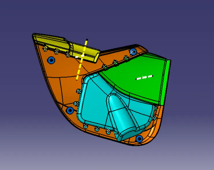
Final Output with the Engineering Features:
Draft Analysis:
Conclusion:
- Input -Master sections and Class A surfaces were studied.
- Tooling axis was created for Class A and draft analysis was performed.
- Developed Class B and Class C surfaces.
- Developed solid parts.
- Created Engineering features such as flanges, Heat stakes and Dog Houses for attachment to BIW components with design guidelines.