Week 11 - Final project
DOOR TRIM PANEL
Door trims are the interior parts that contains the most controls and the decorative parts.
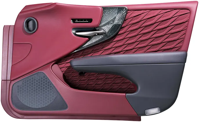
Fig 1. Door Trim Panel
In this project the input surface has been given, we need to create class B and C surfaces and make it a solid, do the draft analysis of the component and also create attachement features like dog house, heat stakes so that the trims easily fits onto the door. Here we will go for top down approach where all the components are created in a single assembly file.
The input surfaces along with the master sections provided to us by the styling team is as follows
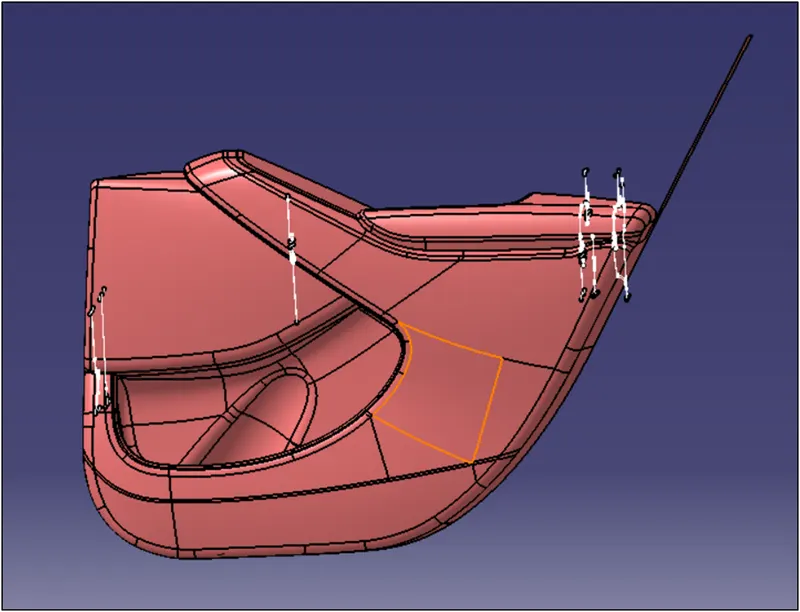
Fig 2. Input surfaces along with the master sections
Arm Rest:
At first we will extract the surface from the input surfaces, check for any discontinuity and if there is any discontinuity solve it or contact the styling team.
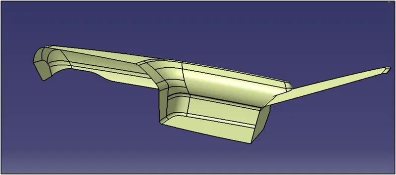
Fig 3. Improved Class A Surface
Then we create a tooling axis for the component.
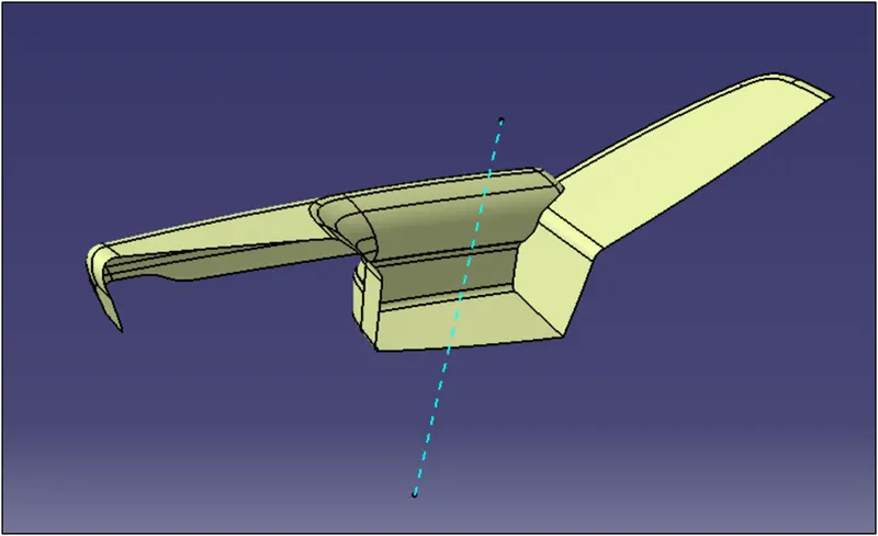
Fig 4. Tooling Axis
Offset the class A surface to 2.5 mm to get the required class B surface. While offsetting there might be discontinuity in the surface which needs to be solved individually. The thickness 2.5 mm is decided according to the master section provided to us.
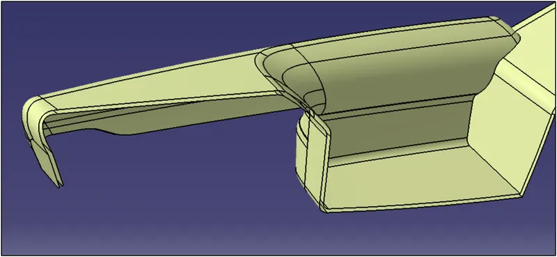
Fig 5. Offseting the class A Surface to get Class B Surface
Then using the Sweep command and taking the tooling axis as the reference direction create class C Surface. Give a draft of 3 degrees.
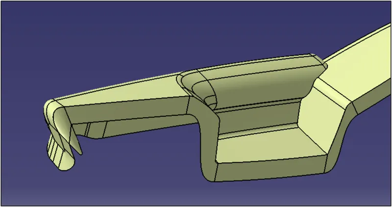
Fig 6. Class C Surface
Finally we trim the surfaces and using close surface command get the required solid component.
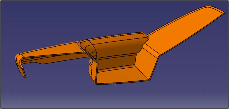
Fig 7. Solid component
Draft analysis is carried out to see whether the part is manufacturabale or not.
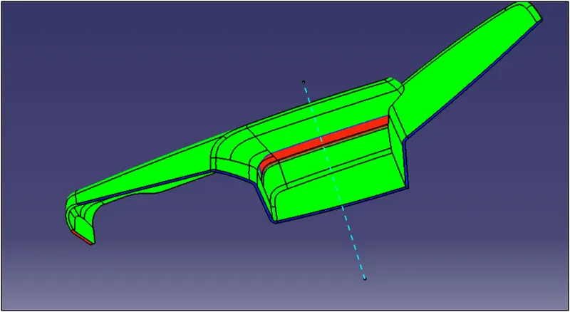
Fig 8. Draft analysis along the main tooling axis
To clear the red areas we need to have a side core tooling axis. So we will create a side core tooling axis and check for draft analysis along that axis.
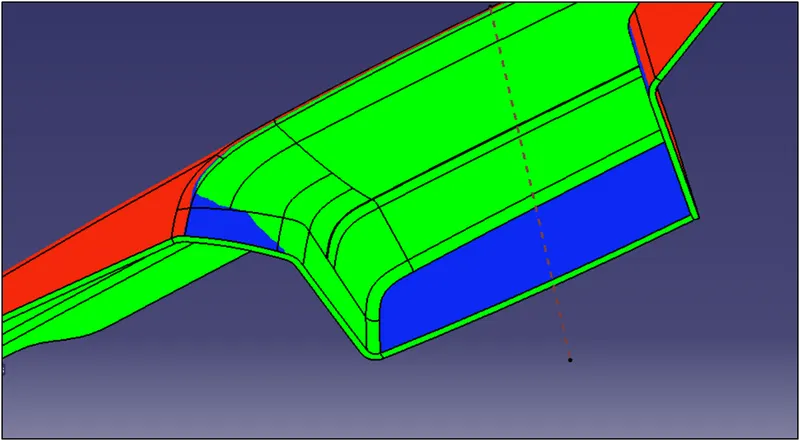
Fig 9. Draft analysis along side core tooling axis
Thus we created the first part, now we will create the second part i.e. the upper map pocket.
Upper Map Pocket:
Extract the surface from the input surface and check for any discontinuity.
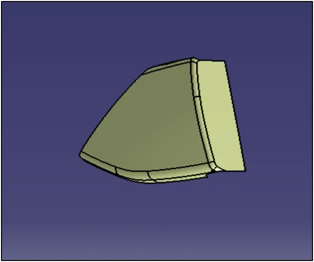
Fig 10. Class A surface
Next tooling axis is created for the part.
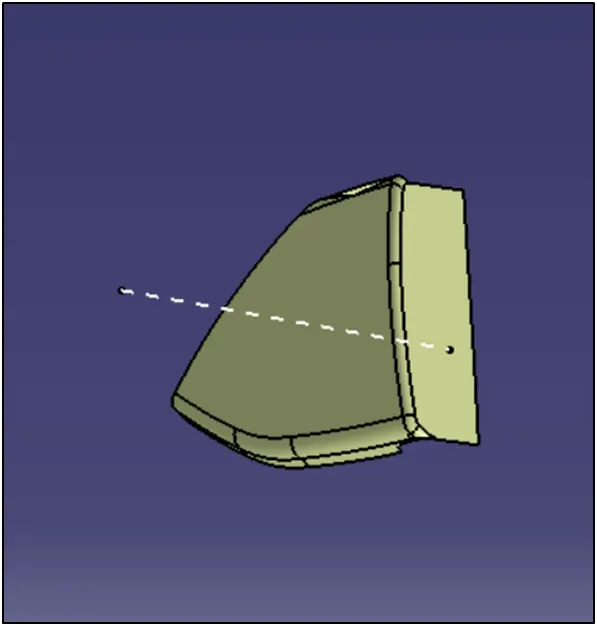
Fig 11. Tooling Axis
Offset the surface to create the class B Surface.
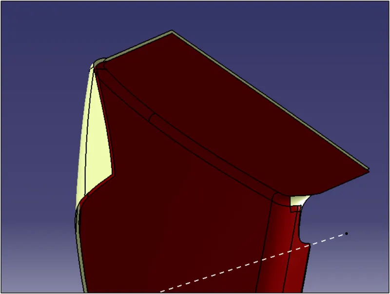
Fig 12. Offseting class A Surface to get Class B Surface
Then using the Sweep command and taking the tooling axis as the reference direction create class C Surface. Give a draft of 3 degrees.
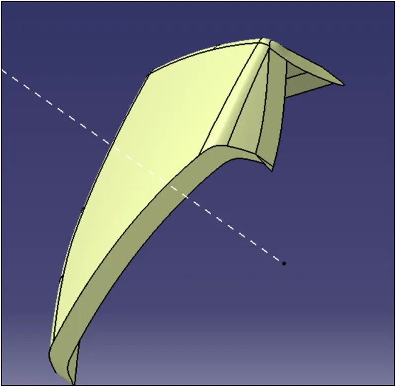
Fig 13. Class C Surface.
Finally we trim the entire surfaces and using close surface command create a solid part.
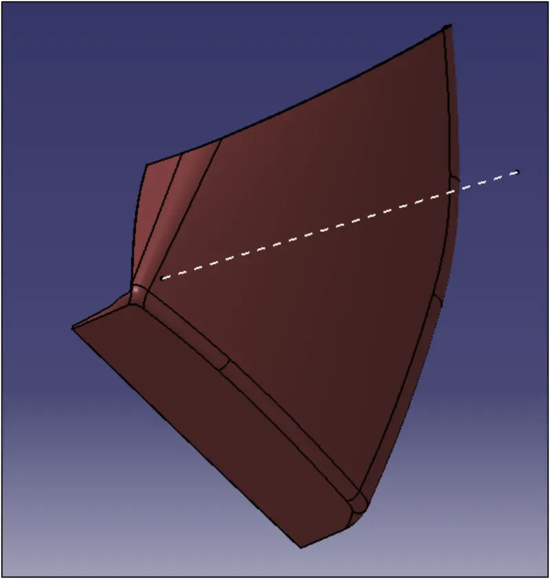
Fig 14. Solid Component
Next step is to check for draft analysis.
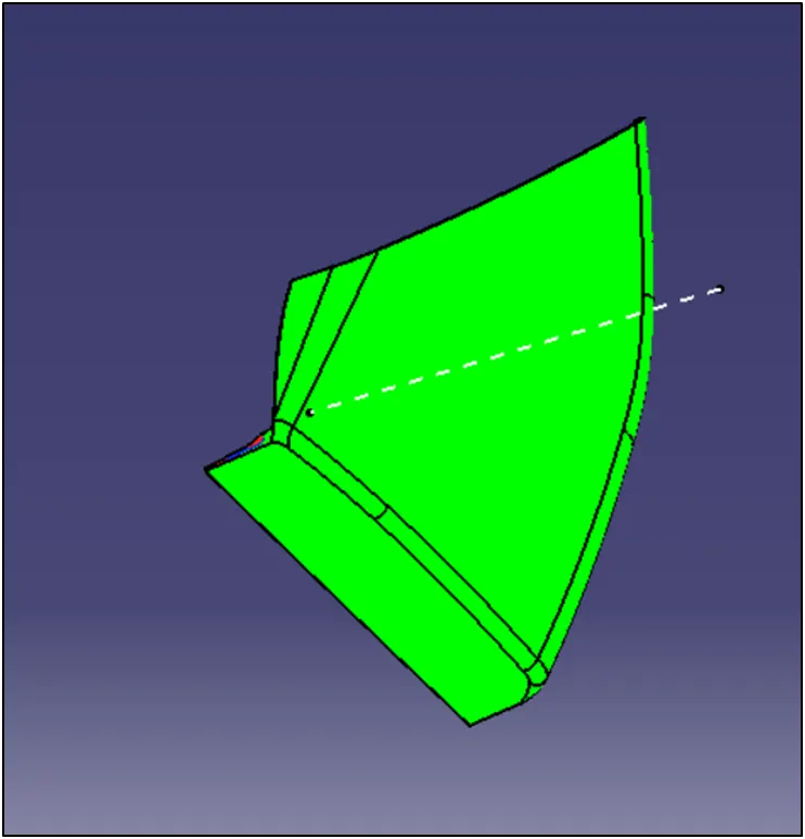
Fig 15. Draft analysis
Map Pocket:
Extract the surfaces and check for any discontinuity.
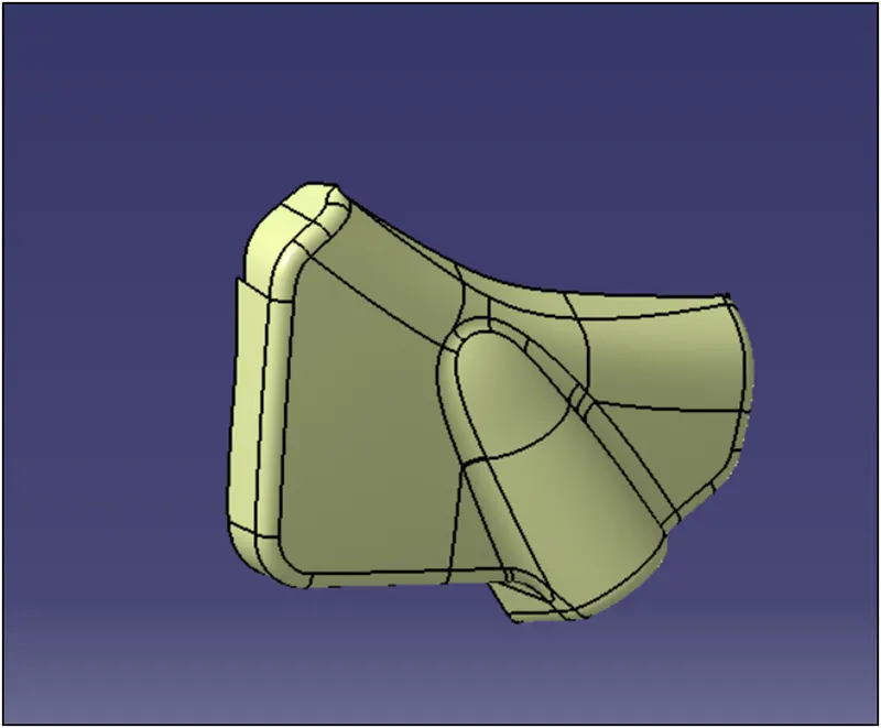
Fig 16. Class A Surface
Create a tooling axis for the component.
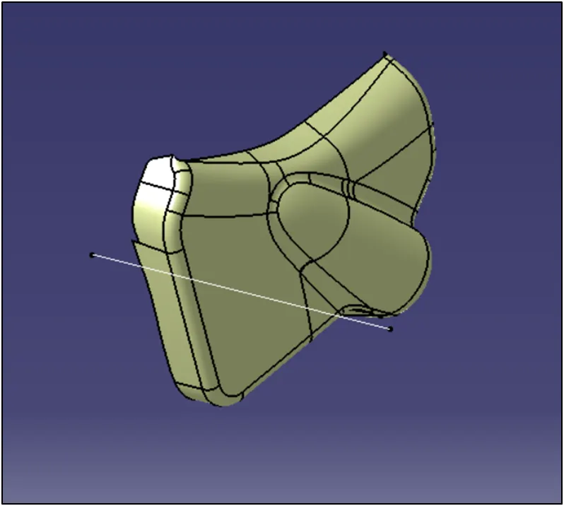
Fig 17. Tooling axis
Offset the class A surface to get the required class B Surface.
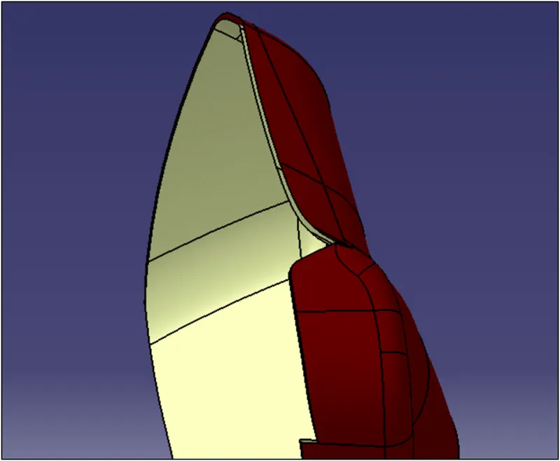
Fig 18. Class B Surface
Using the sweep command create class C surface taking the tooling axis as the reference direction. Give a draft of 3 degrees.
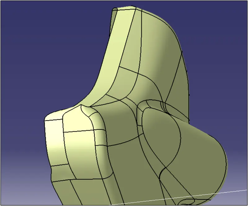
Fig 19. Class C Surface
Trim the required surfaces and use close surface command to get the required solid component.
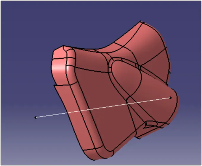
Fig 20. Solid Component
Check draft analysis of the component.
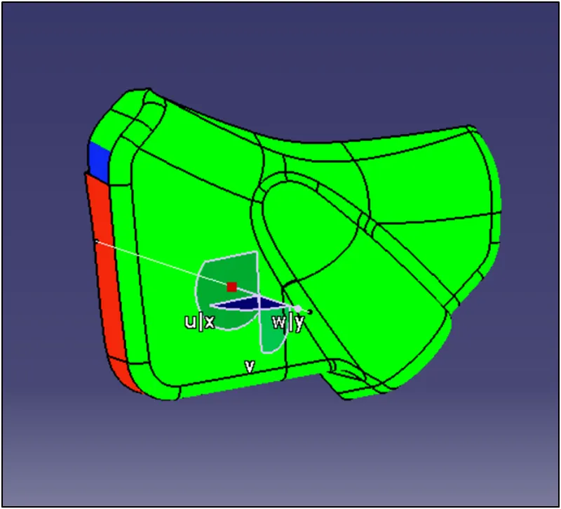
Fig 21. Draft analysis
Lower Substrate:
Extract the surfaces and check for any discontinuity.
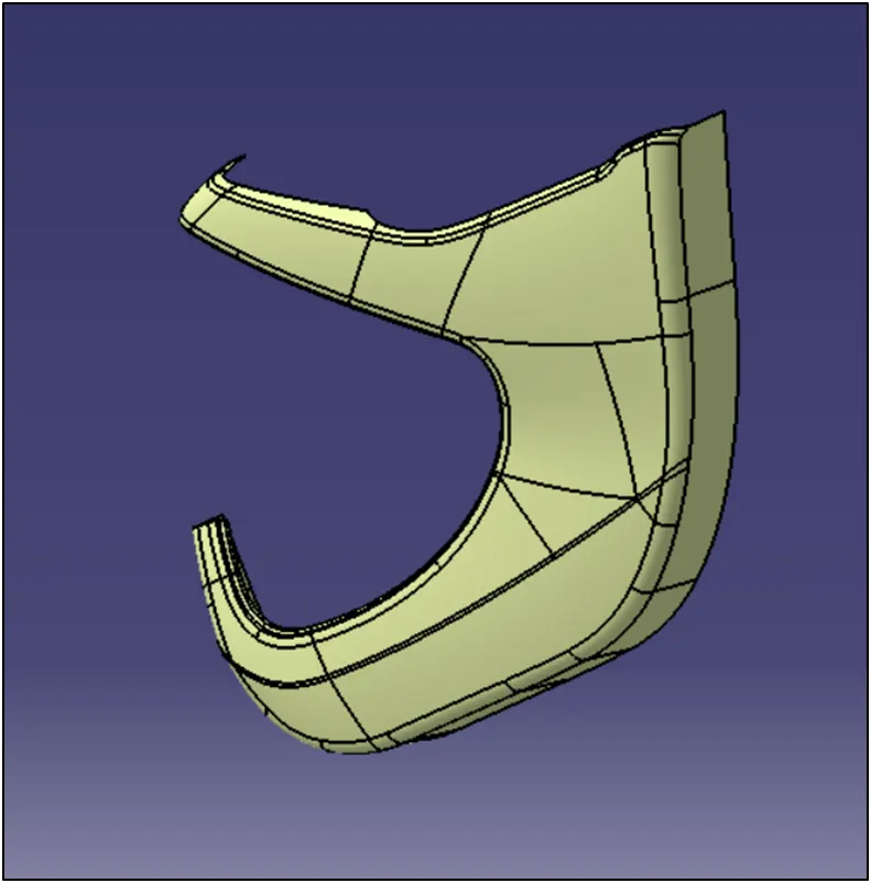
Fig 21. Class A Surface
Create a tooling axis for the component.
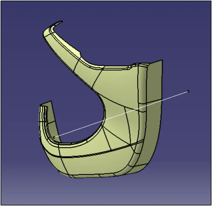
Fig 22. Tooling Axis
Offset the class A Surface to get the required class B Surface.
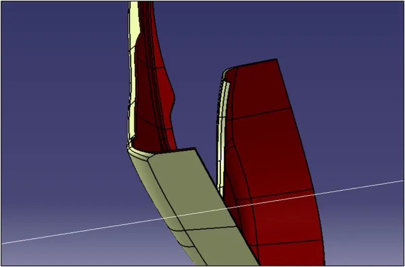
Fig 23. Class B Surface
Using sweep command and taking the tooling axis as reference, create class C surface. Give a draft of 3 degrees.
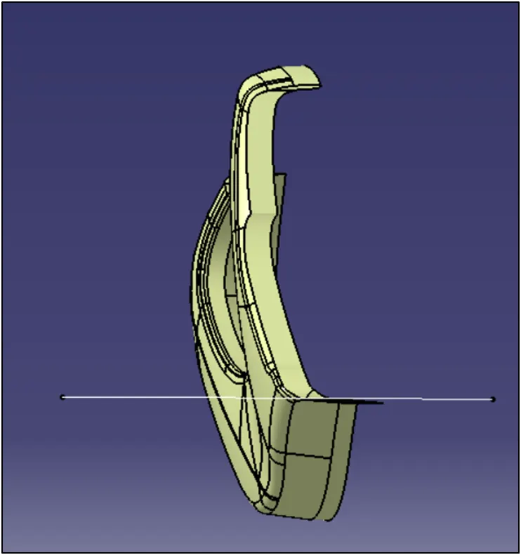
Fig 24. Class C Surface.
Trim the surfaces and use the close surface command to create the solid component.
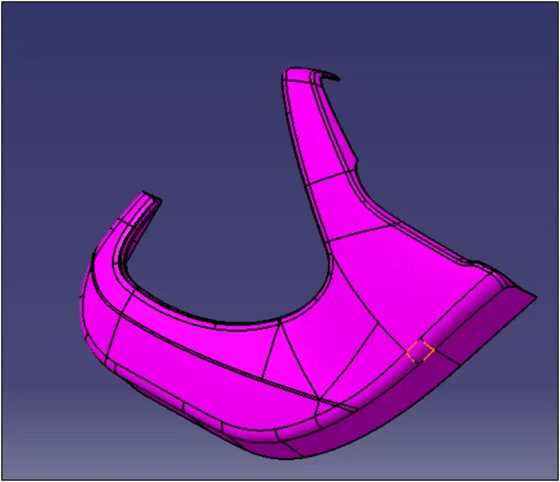
Fig 25. Solid Component.
Next draft analysis is done for the component.
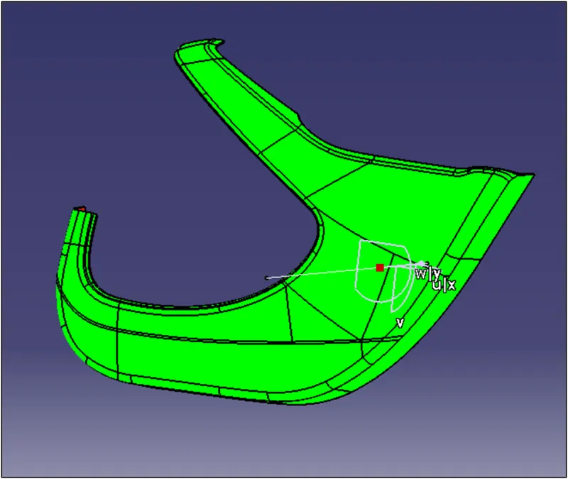
Fig 26. Draft analysis
Thus all the required solid components are required. Now to assemble them we need to have flanges for each of the component and these components will be joined to the lower substarte with the help of heat stakes.
Flanges and heat stakes:
The flanges and heat stakes will be created according to the master section given. give a draft angle of 0.5 degress to the heat stakes.
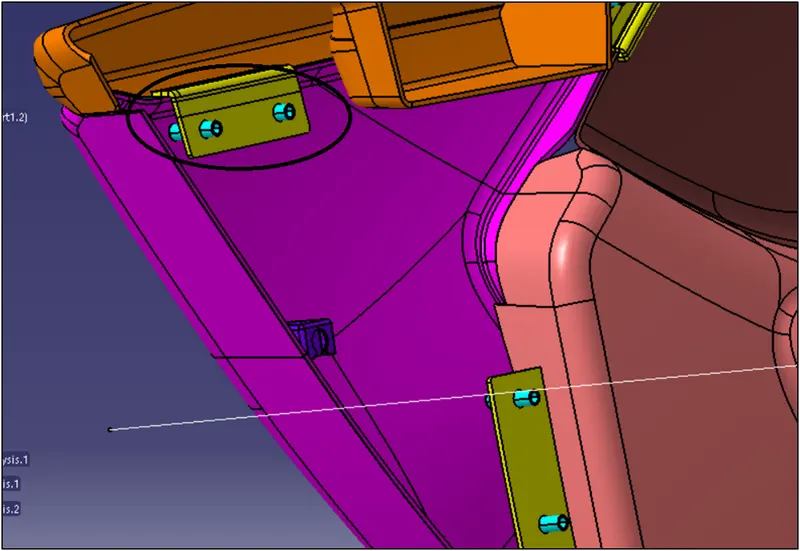
Fig 27 flanges and heat stakes
Dog house Creation:
Dog houses are created on top of which the push clips are fitted so that the panel fits on to the door. All the design parameters are taken into consideration while creating doghouses.
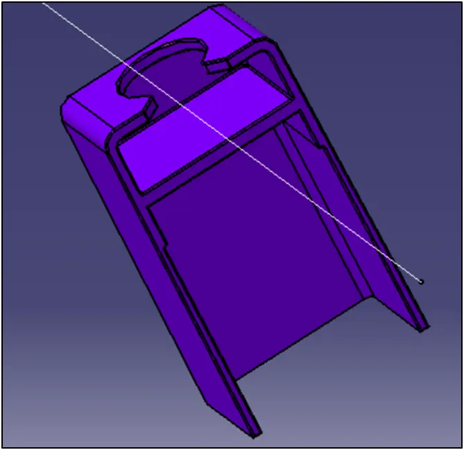
Fig 28. Dog house
Checking draft analysis of the dog house.
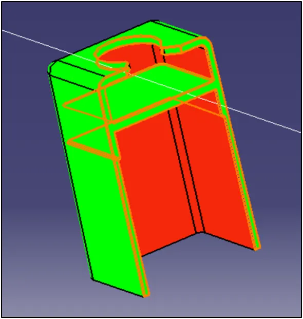
Fig 29. Draft analysis
After creation of all these parts, the parts are assembled together. Push clips are assembled on top of the dog houses.
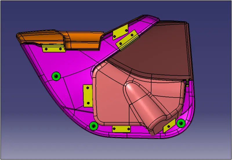
Fig 30. View 1
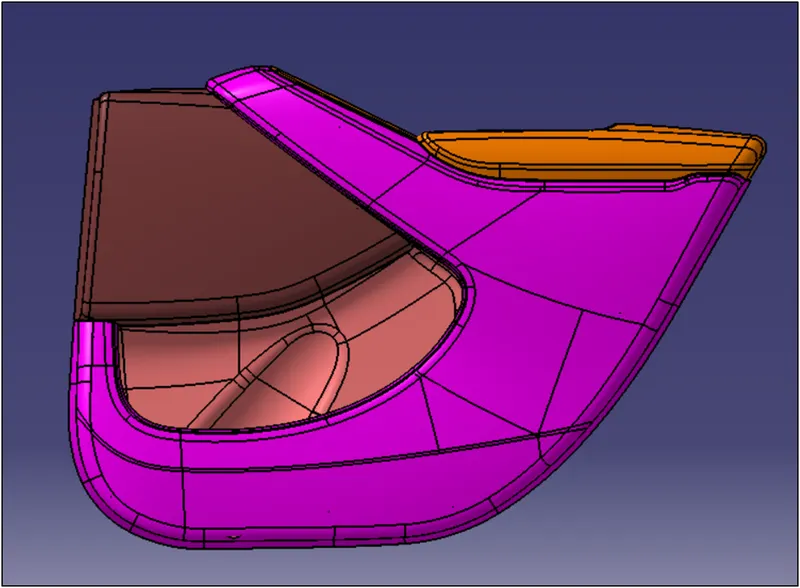
Fig 31 View 2
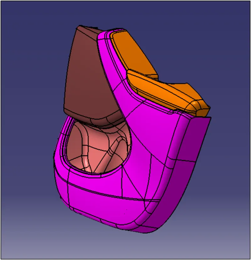
Fig 32 View 3
Conclusion:
Got a good understanding of top down assembly approach in CATIA V5.
Understanding master sketch and its importance in designing.
Gives a clear understanding of attachement features of plastic parts like heat stakes, dog houses.
Got a good understanding of different workbenches used in CATIA and hoe to easily toggle between the workbenches.
********