Week 11 - Final project
Aim:
Side door trim creation using CATIA.
Objective :
- Creating the A class flanges for all the parts of the side door following the master sections.
- Creating B class surface
- Creating the C surface with proper draft direction.
- Engineering or attachment features creation such as heat stakes, dog houses, and ribs.
- Performing the draft analysis.
Introduction :
Plastic parts design is a very complex process and it requires the involvement of many factors like functional requirements, process constraints, material selection, and assembly or structural issues.
Wall thickness, Draft, and Textures, Ribs & Bosses, Holes/Depressions, etc. are some of the important elements to be considered in the design of plastic parts.
Adhering to these basic design guidelines for injection molded parts can improve the moldability of the designs and the life of the mold, increase the operational life of the part and reduce manufacturing cost.
The input of the product designer is in the form of the A-class surface. The job of the product
The designer is to create the B and C surfaces keeping all the aspects for the mold.
Class A is
1.Visible surface and aesthetic look
2.surface with textures
3.Surfaces provided by customer(OEM)
4.Don't have any features like(rib, snap, bosses, etc) on class A surface.
5.Class A surface is made from scanned data with different software like alias etc.
6.Surfaces which is having CURVATURE CONTINUITY IS CALLED class-A.
Class B surface:
1.invisible Surfaces.
2.Surface mostly don't have textures
3.Surface needs to be created according to the class-A surface.
4.having all features(Rib, boss, snap , etc) in B-side surface only.
5.Surfaces which is having TANGENT CONTINUITY IS CALLED class-B
Terms :
Dog house :
It is a ‘doghouse’ looking embossment for screws to attach one piece of plastic to another one. For example, you have a bumper cover, and you want to add a garnish to it. You would use doghouses to do so.
The shaded oval is where the screw comes in and in this example, these doghouses are on the back of an a-surface bumper cover. Now the reason it’s a doghouse is that you want to keep the legs of the doghouse thin so that there are no sink marks on the a-surface.
If a plastic component is too thick (as in where the a-surface thickness of 3mm and the doghouse thickness of say 3mm comes together, you would have a sink mark).
Flanges:
Flanges are the additional layer that is used as an attachment holder which gives strength to the component. It is generally used to connect the pipes, valves, etc. Flanged joints are made by bolting together two flanges with a gasket between them to provide a seal.
Push Pins:
Push Pin or clip is used to hold the door onto the inner panel. The Pushpins are attached to the doghouses and the clips are made of plastic material that can be replaceable.
Heat Stakes:
Heat Stakes is an assembly method that uses the controlled melting and reforming of the plastic stud or boss to capture or lock another plastic or metal component of an assembly in place.
The plastic stud protrudes through a hole in the component to be locked in place. The Heated thermal Tip contacts the top of the stud, which melts and fills the volume of the tip cavity to
produce a head, locking the component in place.
Procedure :
First, open the model in the Generative shape design.
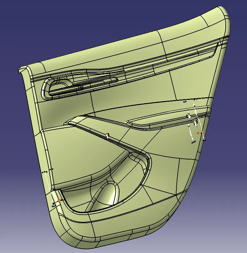
Here the model is A class for the side door with handles and window rails also. But we will be creating the part body for the lower side of the door. The surface over which we will be working is.
- Armrest with pocket
- Armrest support
- Lower body substrate
- Map pocket
- Upper map pocket
The parts were extracted and their graphic color is changed for easy visual purpose.
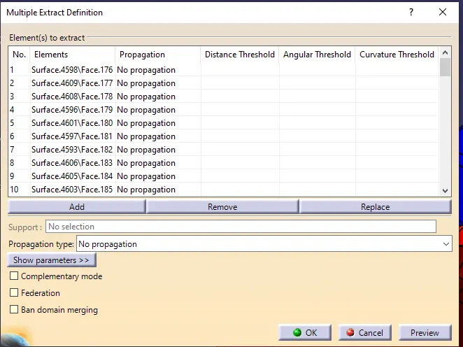
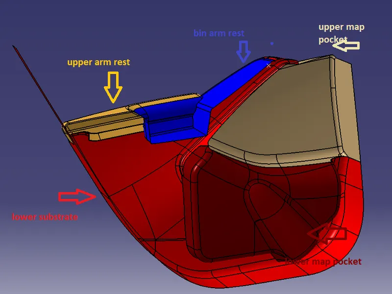
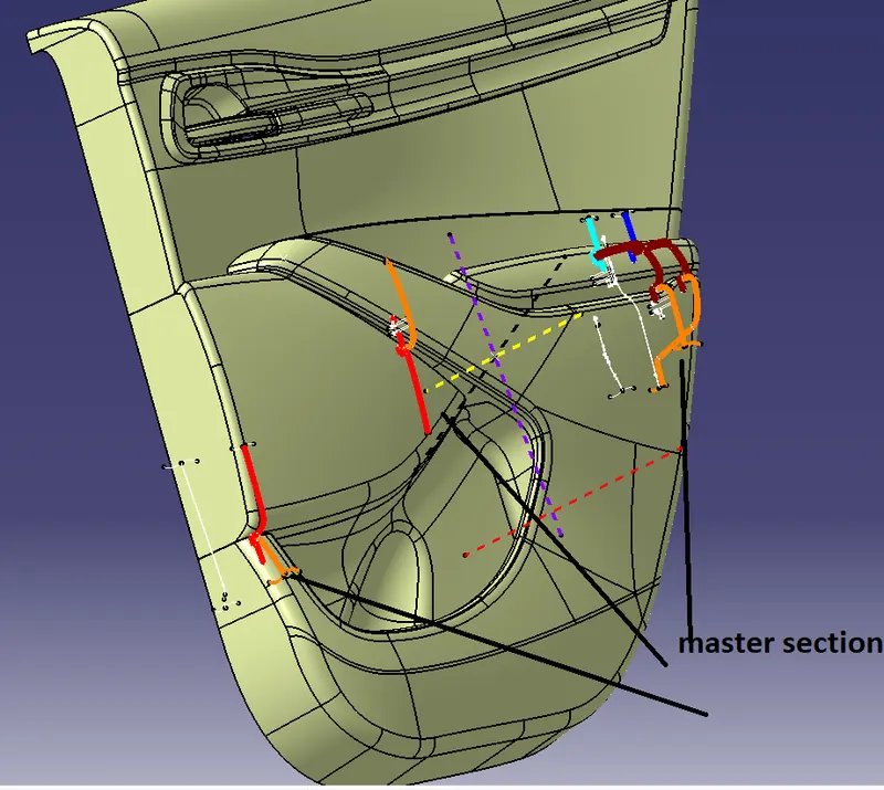
Class A surface flange creation according to a master section:
First, the master section is extracted and highlighted to know the flanges and connection of one part to the other with the attachment features.
Upper map pocket :
We will be creating the flanges for the upper map pocket following the master section for the map pocket.
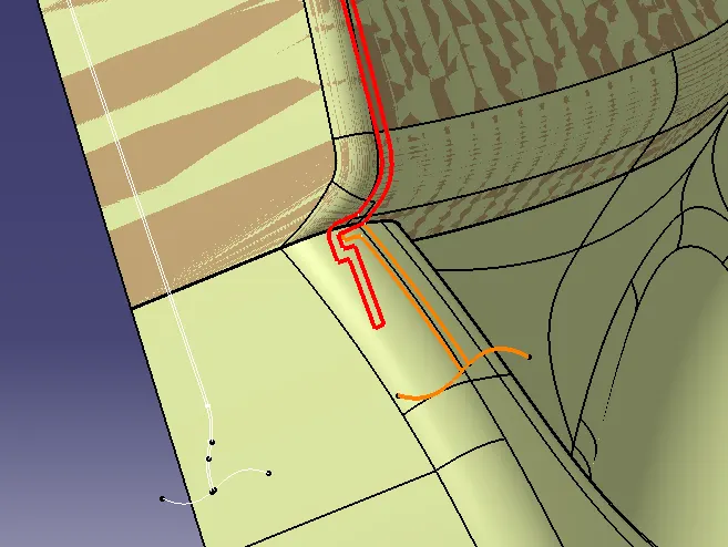
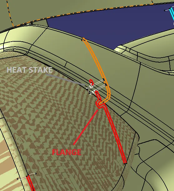
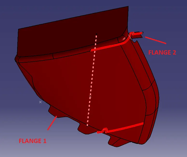
In the above figure, the master section for the map pocket shows the U flange, and it is connected with the lower substrate-like lock.
On the other side, its shows the flanges with heat stakes.
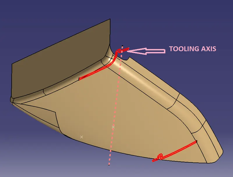
Tooling axis :
- Since the component is visible from the Y direction, so that will be the tooling axis for the upper map pocket.
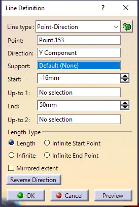
Extract >> point on the surface >> create the line in the Y direction.
Flanges creation :
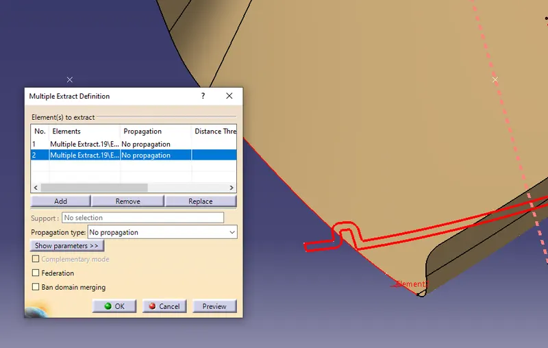
- First the go multi extract >> extract the boundary >>
Smooth >> curvature >>0.001
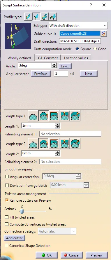
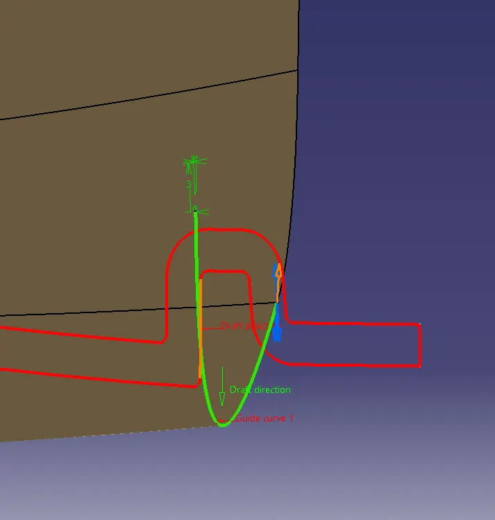
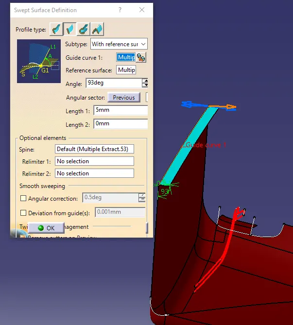
- Sweep >> select the sweep along the draft direction>> give draft angle as 3 degrees >> select the outer direction for the draft.
- For flange in connecting the above-swept surface, we can again sweep the flange with no draft directions but with the reference surface in 90 degrees.
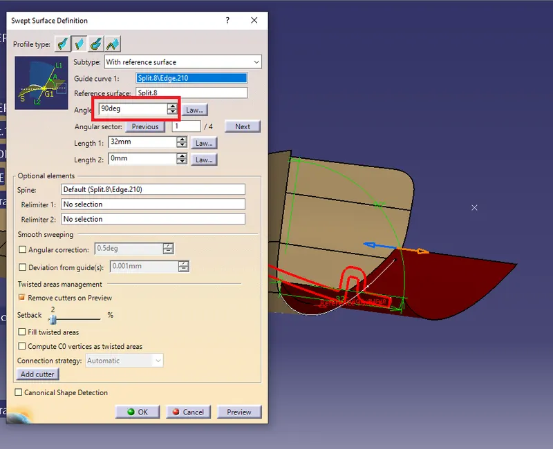
The earlier flange was given the draft direction because that surface lies parallel or in line to tooling direction and it has to clear in the positive draft for proper extraction at the end of the cooling operation.
And the next swept face is already going to be perpendicular to the tooling axis so it will be cleared in injection.
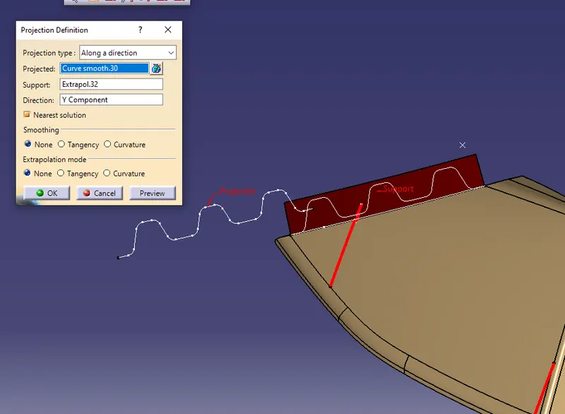
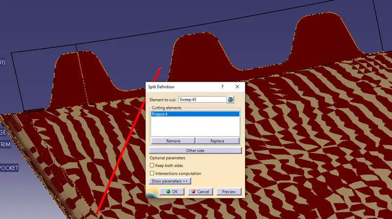
- Creating the flange sketch in the ZX plane and then project the sketch to the flange.
Later on, the sketch is used as a split for the flange.
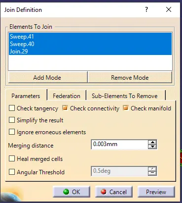
- Then all the surfaces are joined to have the continued connection. (use the boundary option to see if there are any gaps in the joined surface or increase the merging distance to max 0.003mm)
 \
\
C surface creation :
- For the C surface creation, sweep along the draft direction is used.
(instead of extracting the boundary in the sweep only we can extract the boundary and smooth )
- Some regions are difficult to sweep because they follow a different direction. So for this region, we use multi section surface for creating the surface between two surfaces using the guide the curve.
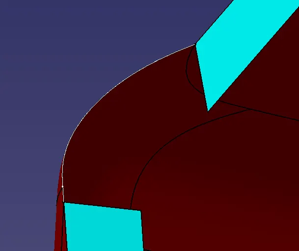
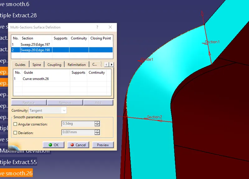
- Or another method used is blend to create the surface in the region where there is no proper guide curve or corner surface creation.
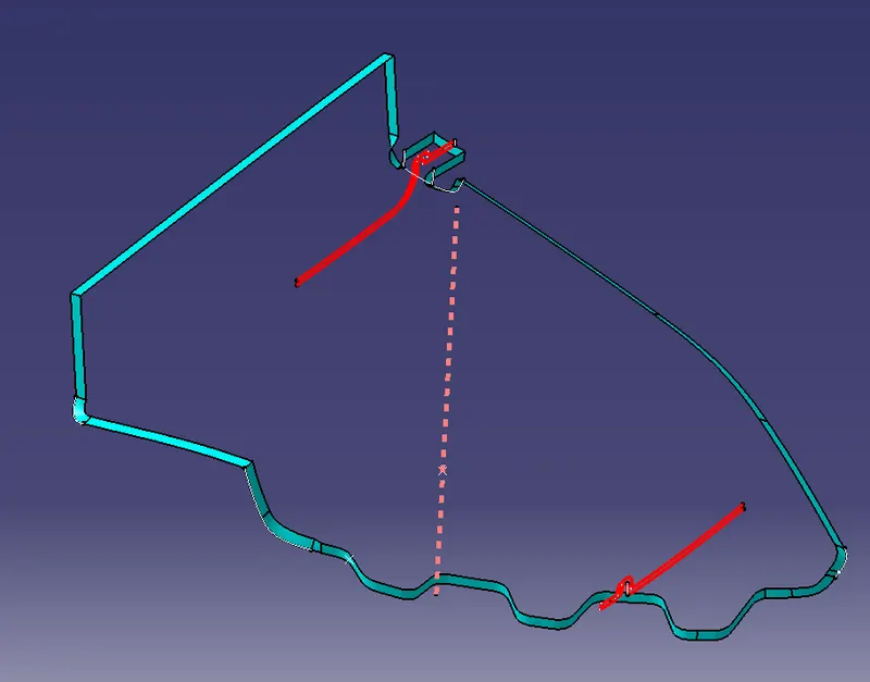
- Like that the surface is swept and joined using the extrapolate followed by trim to form the C surface and finally they are joined to form a continuous surface.
B surface :
- B surface is formed by offsetting the surface to the value 2.5mm i.e the thickness of the component.
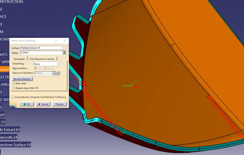
B surface is the side where all the special features and attachments are present which is not visible to the viewer at the final assembly.
- Here also the multisection and blend option is used to create the surface is the complicated regions.
- Finally, the edges of the B surface are extrapolated to extend beyond the C surface such that it can be trimmed without any connectivity error.
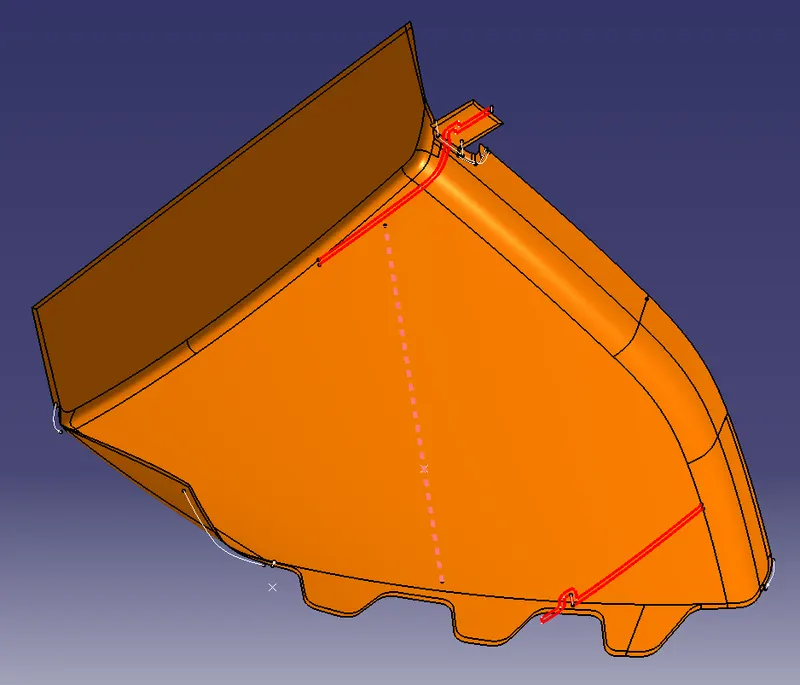
Final Upper map pocket body creation:
- At first, the A and C surfaces are joined or trimmed together without any gaps among them.
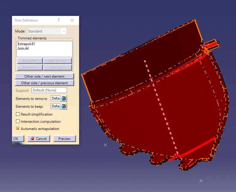
- For joining the two surfaces maximum allowable merging distance is 0.003mm. It’s advisable to use a boundary tool to check for gaps between two surfaces beforehand.
- Later on, the B surface is trimmed with the A-C surface to form the final component.
- It is still a surface so it does not have mass unless it is thickened. Switch the part design>>insert the body>>closed body
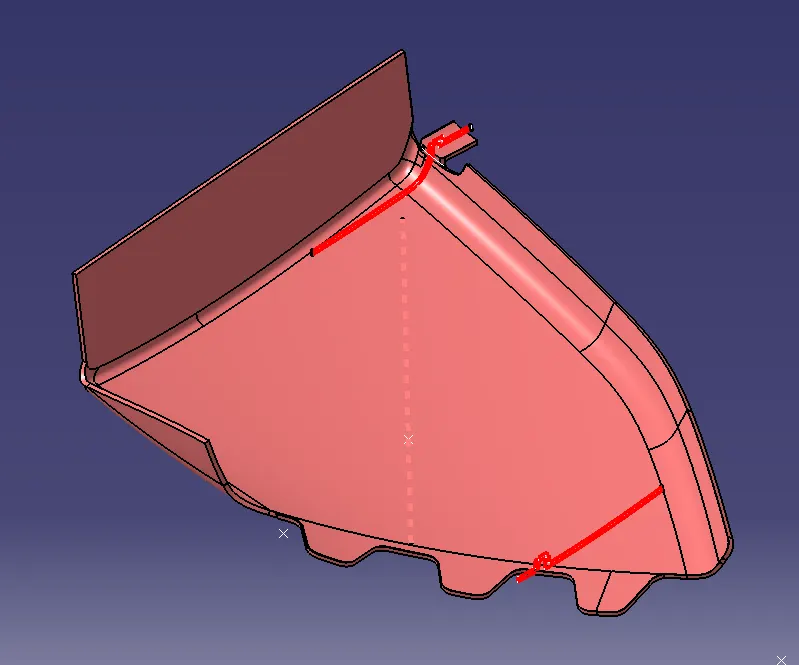
Armrest :
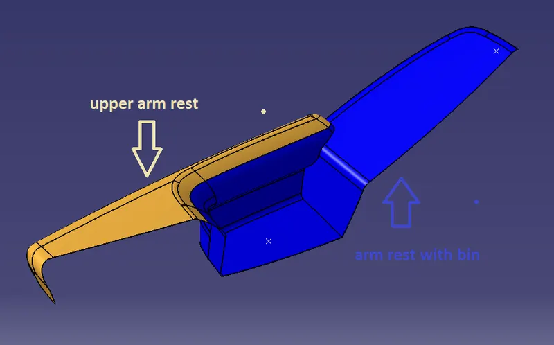
The armrest is divided into two i.e with the bin and the other being the upper side.
This is done because it’s a bit complicated surface that cannot be manufactured in a single operation or with a 1 tooling axis in the molding operation.
Bin part surface creation:
Tooling axis :
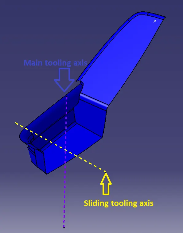
- The bin parts of the armrest have 2 tooling axis, one being the main tooling axis and the other being the sliding tooling axis to clear the curved portion of the bin region.
- The main tooling axis is along the X direction which clears the majority of the area.
- The sliding tooling axis clears the bin region along the Y direction.
Surface creation:
B surface :
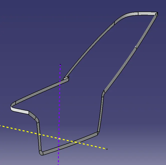
- Before extracting the B Surface, the flanges need to be created so that the heat stakes can be attached to constraint the model.
- The flange is created concerning the master section and the strip is created with the holes that constraint the heat stakes.
- But the master section has given consider the armrest as a single component. The armrest bin portion is connected to the upper armrest and the lower substrate with help of flanges and heat stakes
- Join the flange strip with the Class A Surface.
- Now select the offset option to create a B Surface with a thickness of 2.5mm.
The B surface is created.
Class C Surface:
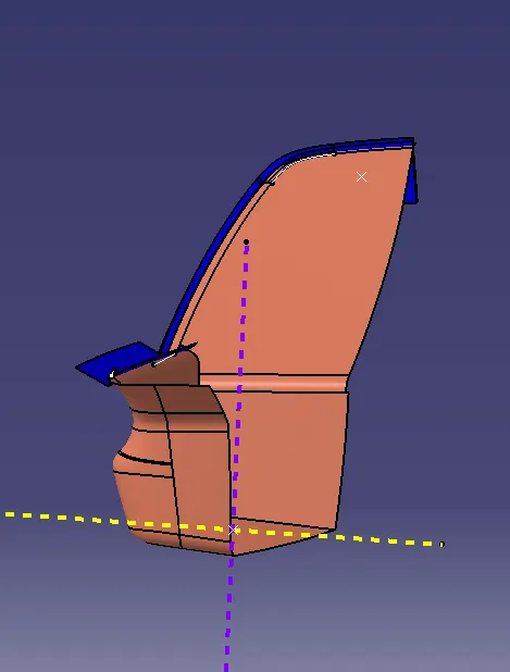
- The class C surface is created with the help of the A surface by using the sweep option.
- The sweep is created with the draft angle of 3º and at regions, the sweep should be a straight line.
Class C is Created.
\ 
Final trim creation:
- Now, Select the Class A and C Surfaces and join them.
- After joining them, trim the surface with the Class B surface to complete the closed body.
- Check the Part for any open surfaces.
- After Creating the closed surface, go to the Part design and select the closed boy option to make the surface into the solid.
- After Creating the Solid Surface, the Draft Analysis is performed to check if the parts are clearing with the draft direction.
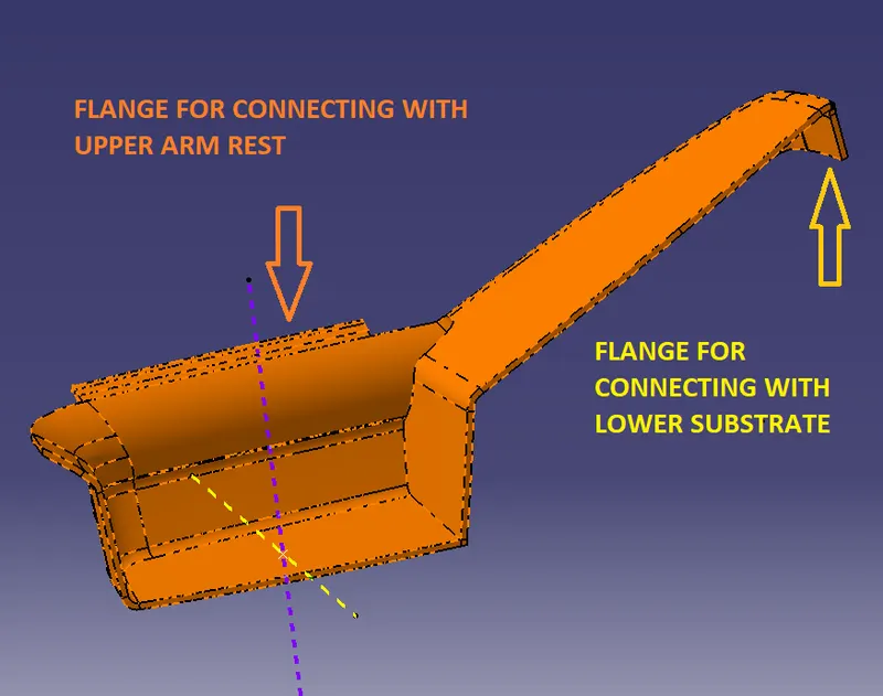
Upper armrest:
- The tooling axis is created by drawing an arbitrary line that covers most of the parts.
- Then drafting analysis is performed and the axis is set by rotating and locking the axis orientation.
- Creating the final axis along the compass direction.
- The surface creation for the upper rest is the same as above.
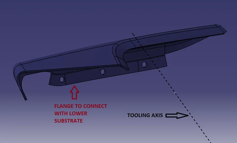
Attachment features :
Heat stakes :
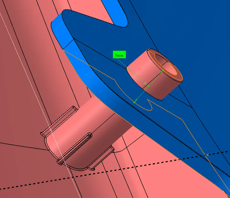
- Heat stakes are features used for locating and constraint the degrees of freedom of the part.
- To create the heat stakes, sketch a circle of a diameter of 8mm.
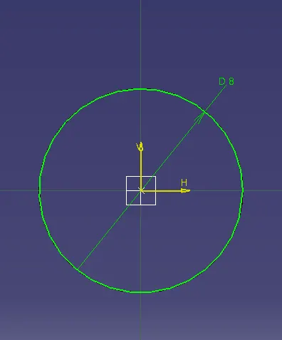
- Extrude the circle to any appropriate length in generative shape design.
- Now, move to part design and thickened it 2mm to inside. (all this dimension are standard design parameters for engineering features)
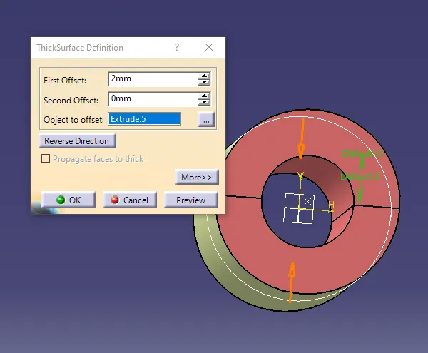
- After creating the heat stakes, create the points on the surface at the location required.
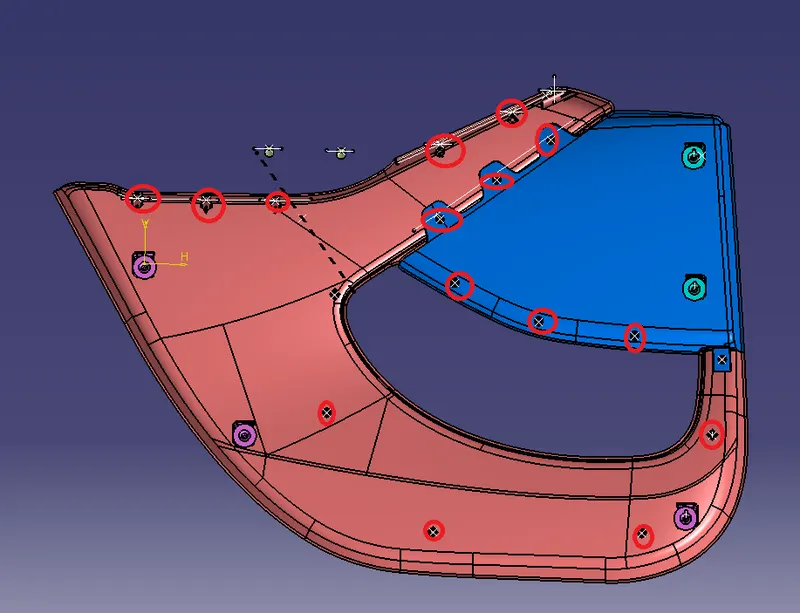
- Use the copy and translate from point to point to finally locate the heat stakes.
- Later on use union trim to add the heat stakes to the lower substrate, map pockets, and armrest.
- Give the draft 0.5 degrees to the inner and outer sides of the heat stakes.
- Ribs are attached to the end of the heat stakes for general stiffness or stability purposes.
Note: The heat stakes should be located in a way that the distance between the upper face and lower side should be 7mm
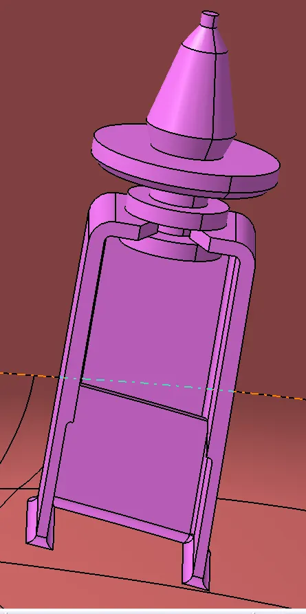
Dog houses :
- The dog house is created along with the locators and push pins for fixing purposes.
- To create the Dog House, Draw a sketch facing 3 sides shaping it in a form of a rectangle. Select the Sketch and Extrude the surface.
- Go to the Part design and use the Thick surface option with a thickness of 1.75
(0.7*2.5=1.75 as per rule )

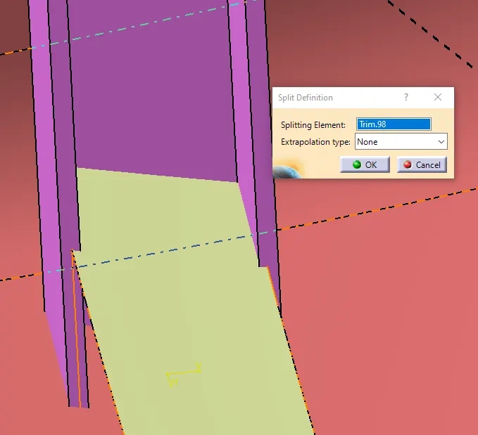
- For the lower part sink mark remover of the dog house, the inner walls of the box are extracted and offset by 1 mm to the outer side in a shape generative workbench.
C= 0.4*2.5 = 1 mm
- Now, offset the surface from the base to 15 mm such that the sink marks are not formed.
- Trim the Surfaces together creating the sectioned surface.
- Now, go to the Part Design and use the split option to reduce the edge thickness to avoid the sink marks.
- Once the Dog House is created give the fillets to the components. And use the Boolean operation so that the part is attached to the Lower Substrate.
Note: Generally the height of the dog house can be arranged according to the sheet metal component present over which this plastic door will be assembled.
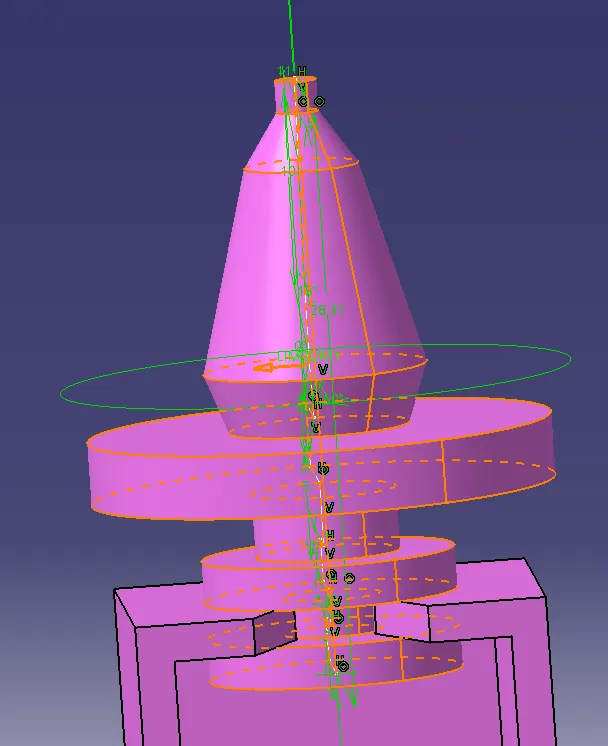
Push Pins:
- The pushpins are the attachment to the Dog Houses which helps to join with the other component features by locking it.
- To Create a Pushpin a design is followed and the sketch is drawn with reference to the below image.
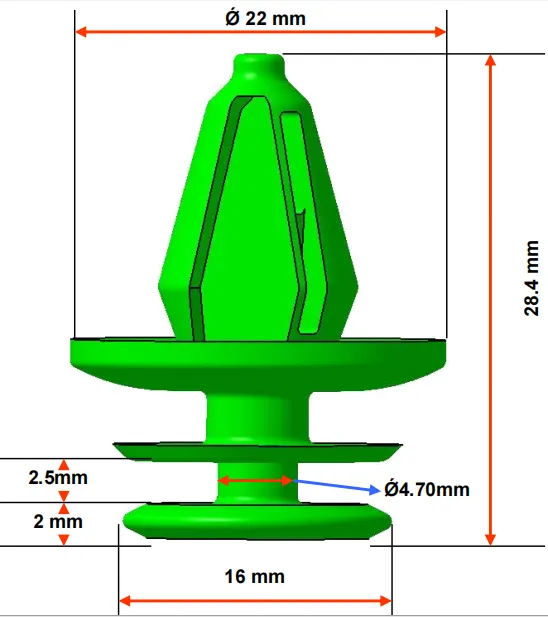
- The Shaft option is used to rotate the sketch to create a circular part.
- Now use the translate option to fix the pushpin on the Dog House.
- Use the Copy and Translate option to attach the Pushpins into the dog house.
RESULTS :
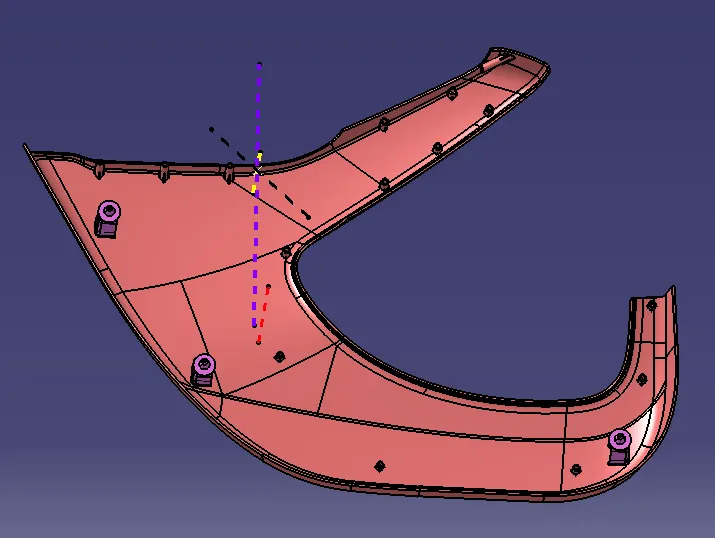
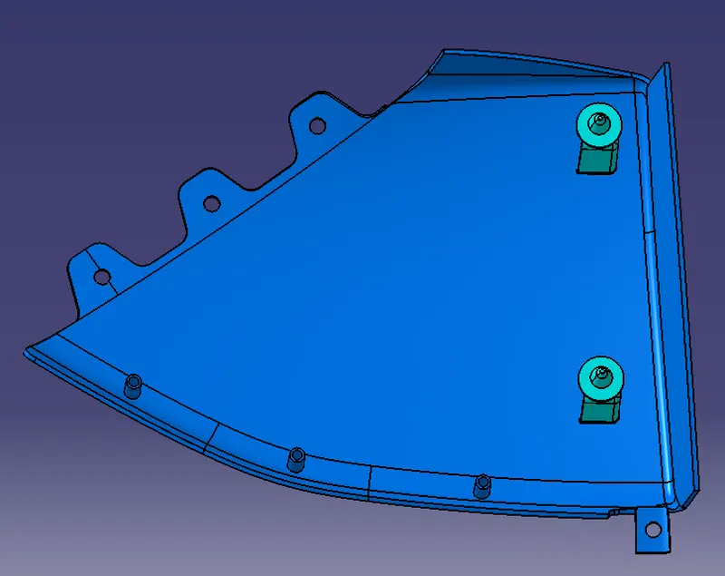
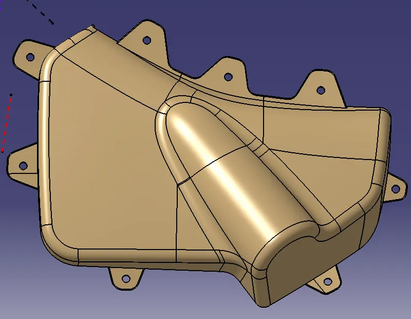
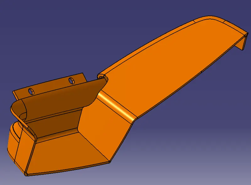
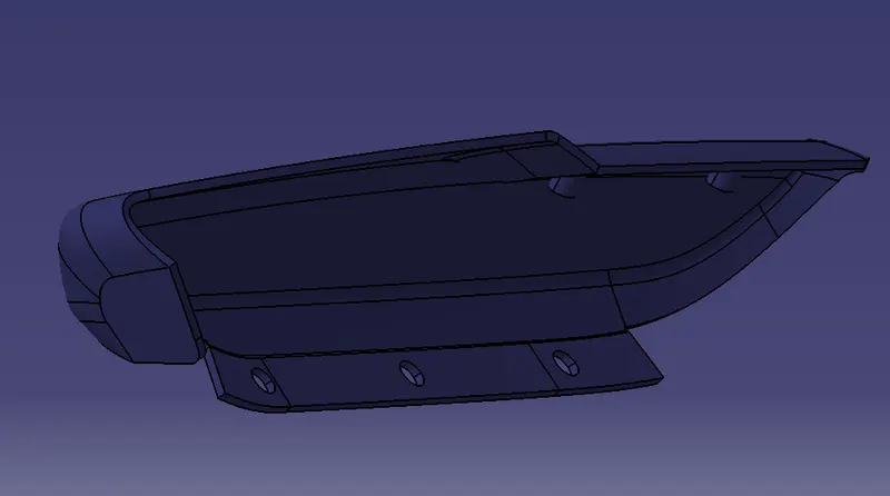
FINAL PART BODIES OF THE INNER DOOR TRIM :
Draft analysis :
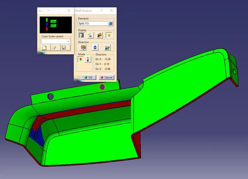
1. a-Draft analysis of the armrest on the main tooling axis :
b. draft analysis along the sliding axis :
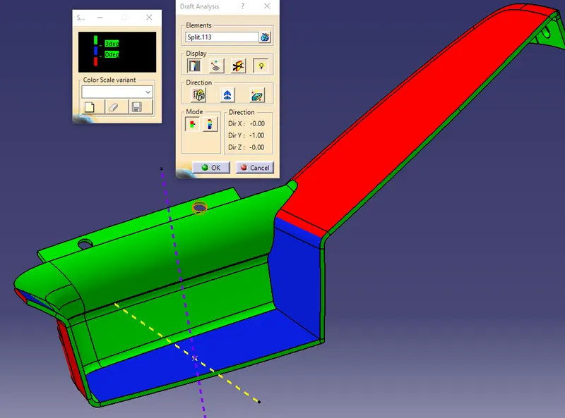
The draft along the main tooling axis covers most of the region of the armrest except for the curved portion. So for proper feature capturing the slider needs to provide for the bin section.
2. Draft analysis for upper armrest :
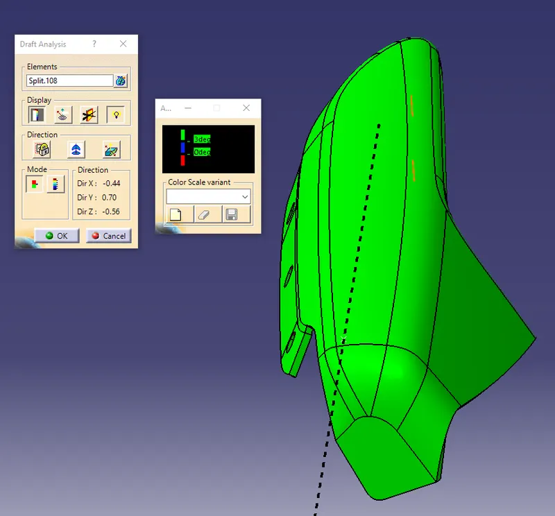
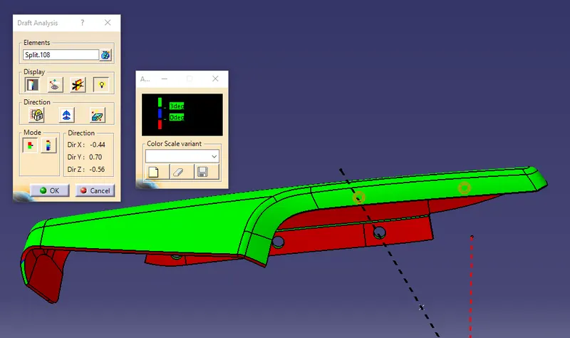
3. Draft analysis for lower substrate :
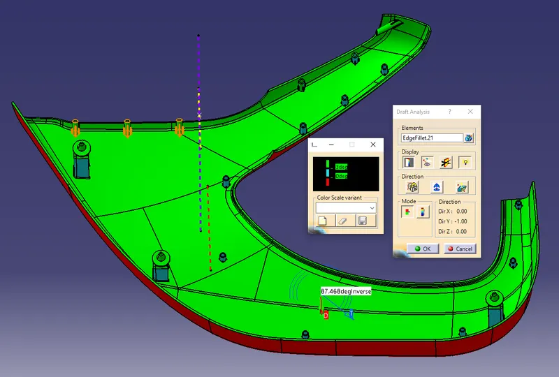
For the engineering features, the draft value in the color scale needs to changed to 0.25 to clear them in the draft.
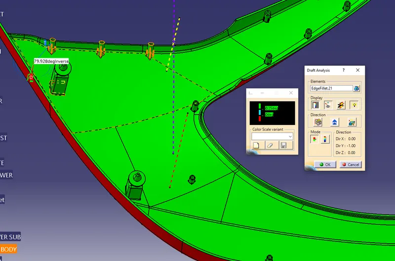
4. Draft analysis for the map pocket :
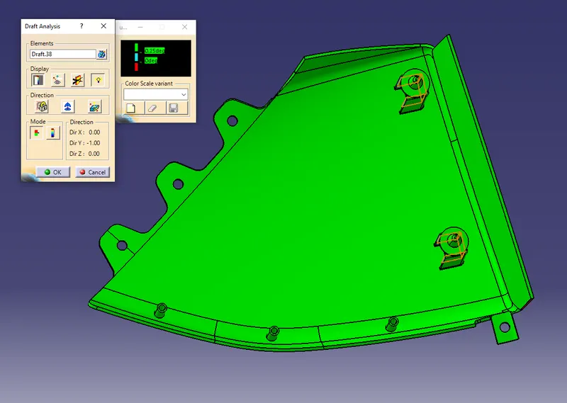
5. Draft analysis for the lower map pocket :
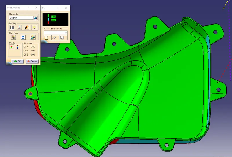
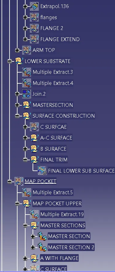
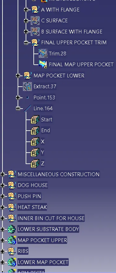
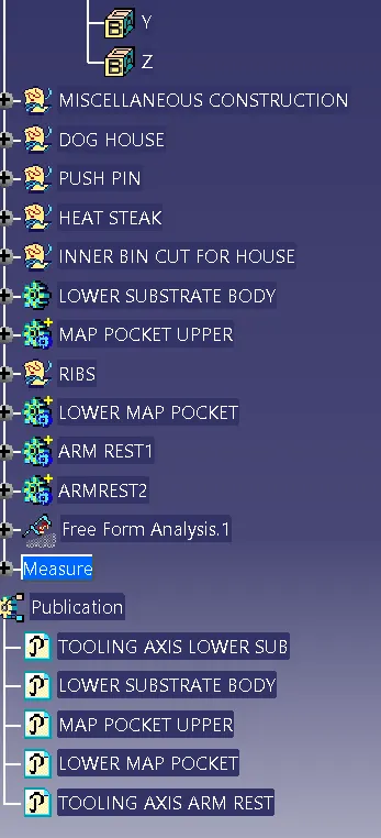
Tree structure :
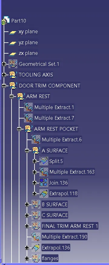
]'
CONCLUSIONS:
- For connecting the different parts master section was followed in most of the region but at some places, those were not followed. For example, the armrest was split into two parts so we have to create the flanges and heat takes to join them.
- All the parts body created were given the specified draft angle to make an injectable component in injection molding operation.