Week 11 - Final project
Week 11 - Final project of Automotive plastic design in catia v5:
Objective:
- Development of a Door Trim panel
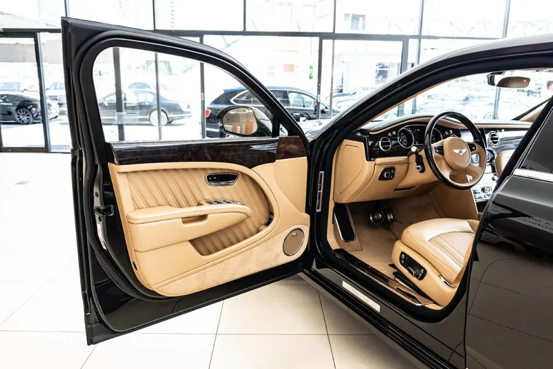
Creation of CAD model considering following inputs as like in OEM and tier1 companies
- a) Class A surface
- b) Nominal thickness: Refer master sections
- c) Attachment strategy:
Find an attachment strategy for the door panel complete work.
Use Push pin with Dog house for Lower substrate – Door panel attachment
Use heat stakes for part-to-part attachment
Output required:
- Create thickened part using master section for reference
- Create the mounting features as per design guidelines in the industry and with master sections
- Apply material details:
- Draft analysis & Tooling analysis
- Creation of parting lines and check tooling feasibility
What is car door panel?
A door card (in British English) or a door panel (in American English) is an insert on the door of a vehicle that covers the door's internal components, giving a topnotch look with protecting occupants getting hurt with biw parts.
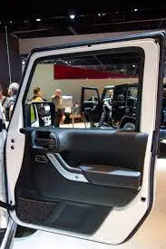
So, in this project we’re going to crate class B and C surfaces and join them together with class A surface to create a solid part, so that let me show you how I've done that.
Class A surface:
Class A it’s an aesthetic surface which is going to be seen by customer of the product.
Class B surface:
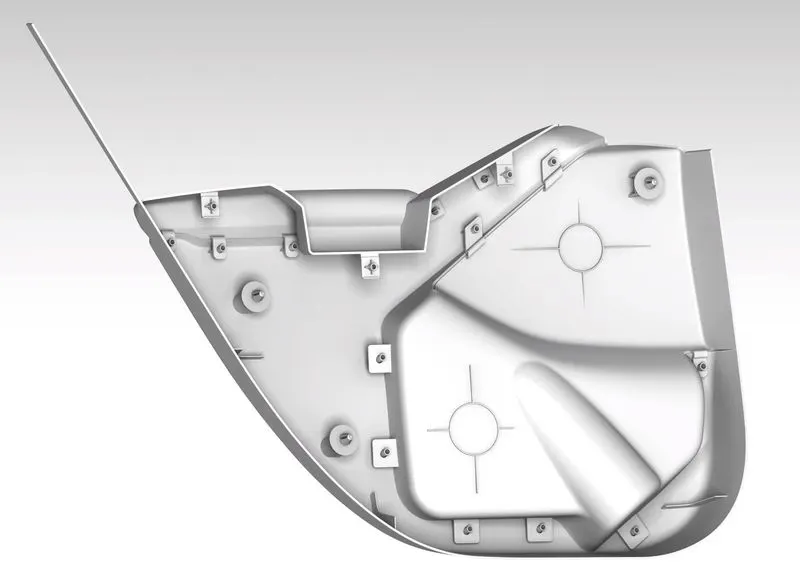
This surface can’t be visible but this surface will have some engineering features such as screw boss, dog house, stiffeners and heat stakes then so on over itself.
Class C surface:
This surface will be joining the class A and B surfaces and it does provide some amount of thickness for the component.
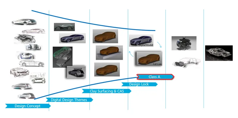
Given data:
Class A surface with master sections of Attachment features
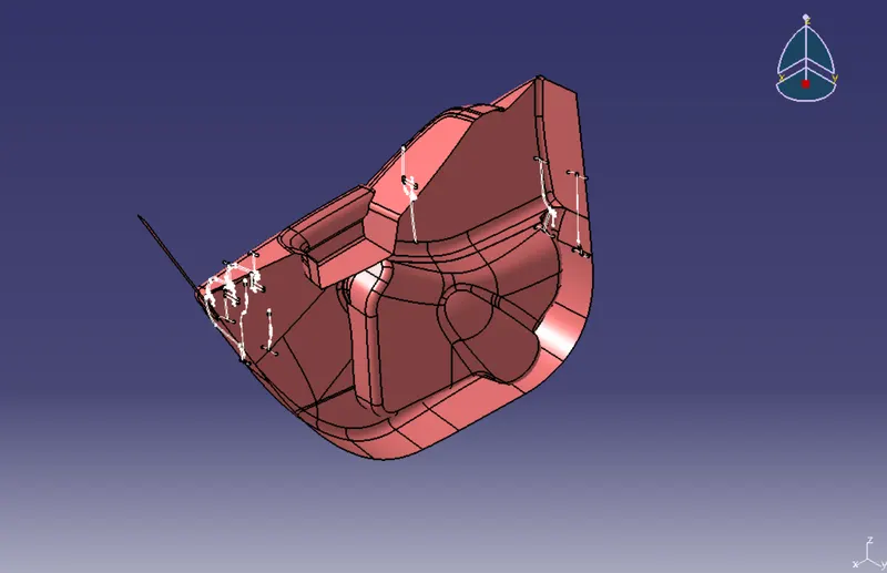
What is draft analysis?
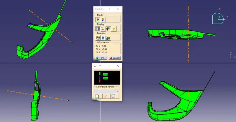
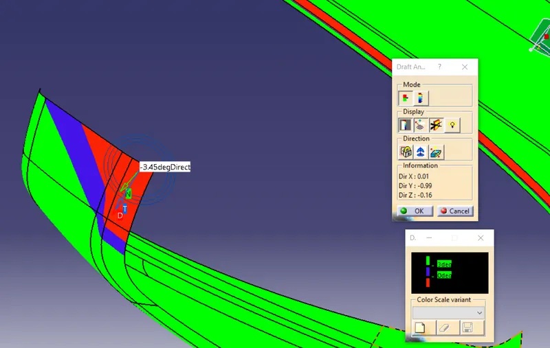
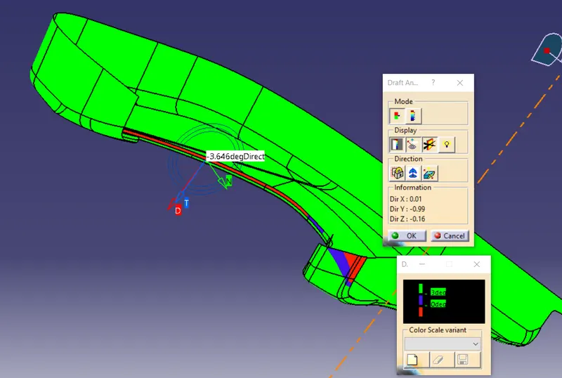
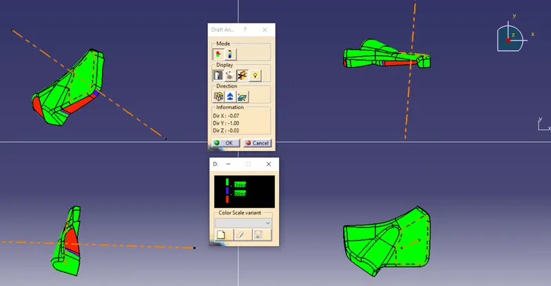
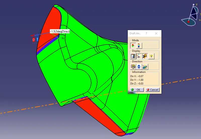
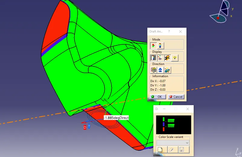
In catia workbench there will be a tool draft analysis which enables you to detect if the part you drafted will be easily removed. This type of analysis is performed based on color ranges identifying zones on the analyzed element where the deviation from the draft direction at any point, corresponds to specified values.
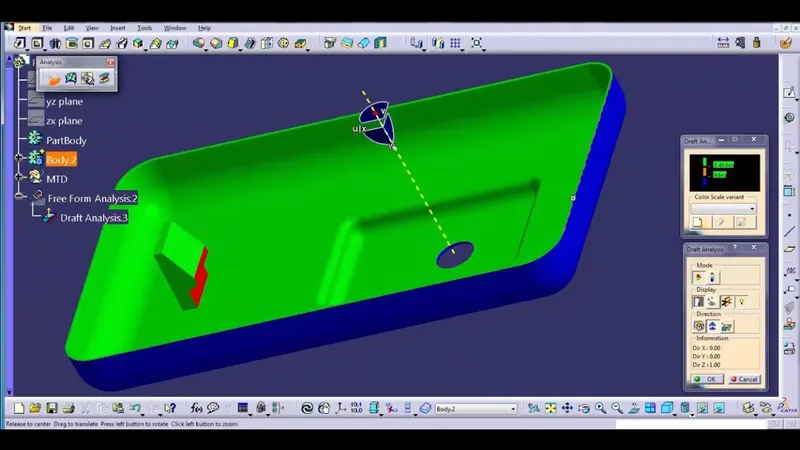
Draft analysis reports of class A surfaces: door arm rest:
essentially, it’s a collaboration of two components for now I've taken this one as single component.
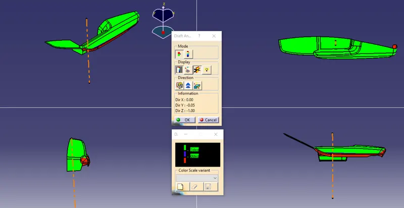
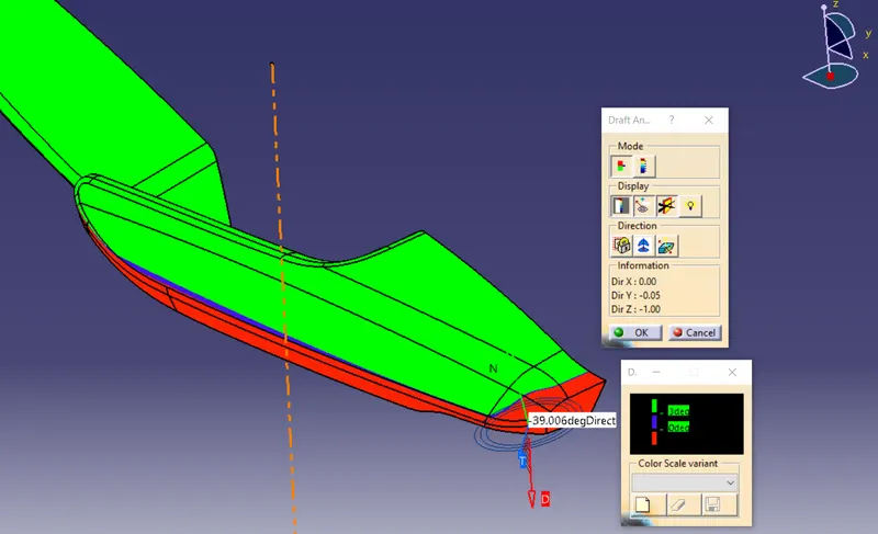
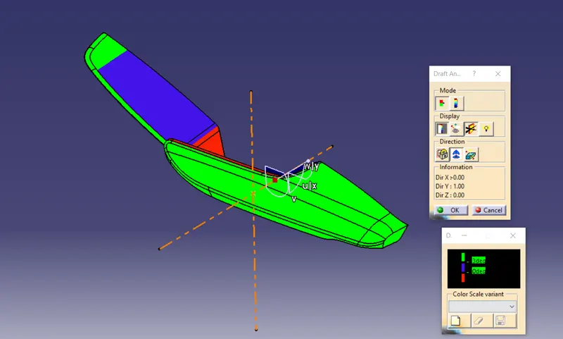
Lower substrate:
Map pocket:
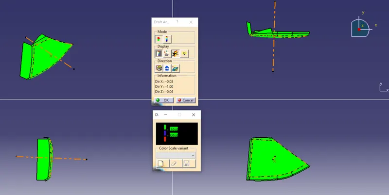
Bottle holder:
My perspective on draftanalysis report of class A surface:
Whlie am i performing draft analysis i could find some negative drafts on the surfaces of bottle holder, door arm rest, then bottle holder those all between 2 to 3.5 degrees on each of the class A surfaces that i mentioned so i suggest to the class A team to add somemore of drafts in that perticular spots on the class A surfaces.
So, for create a solid part we should create a class B and C surfaces
Door arm rest:
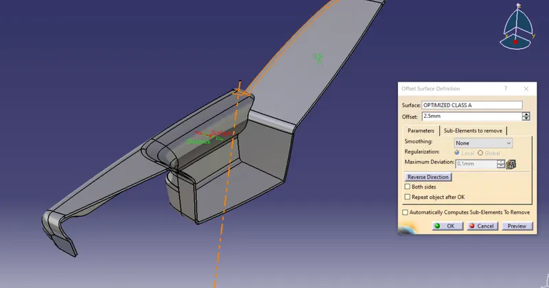
Offseting class A surface about 2.5mm for create class B surface.
Class C surface:
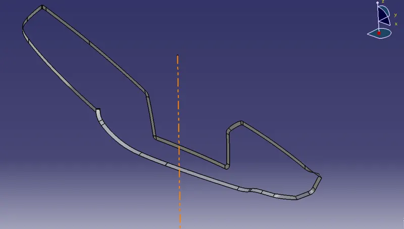
Closed surface body:
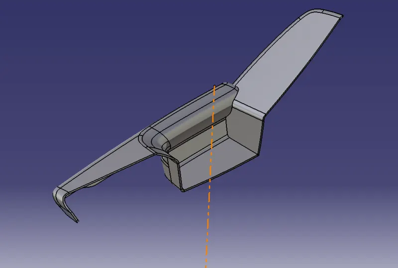
Solid part:
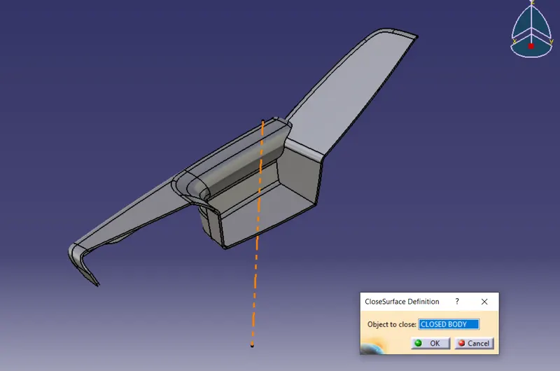
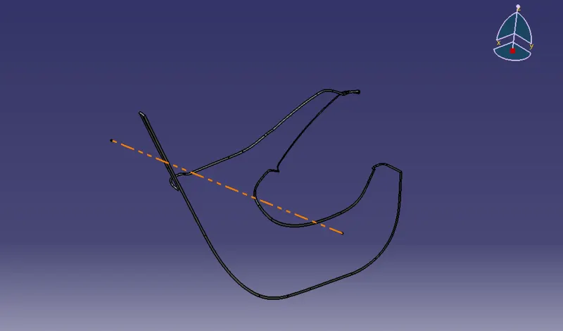
Lower substrate:
Offseting class A surface about 2.5mm for create class B surface.
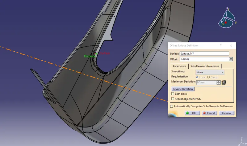
Class C surface:
Closed surface body:
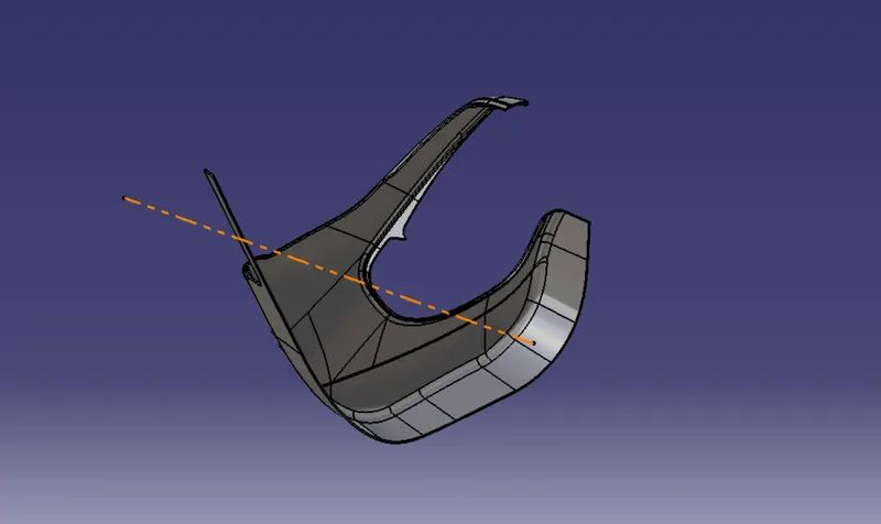
Solid part:
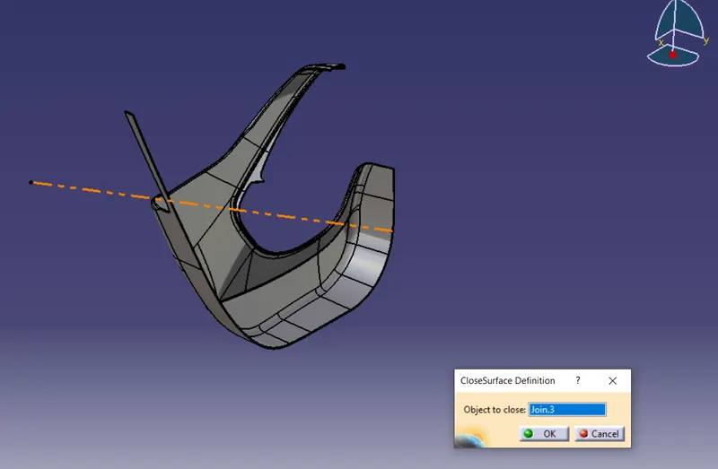
Map pocket:
Offseting class A surface about 2.5mm for create class B surface.
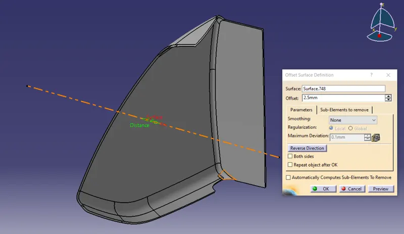
Class C surface:
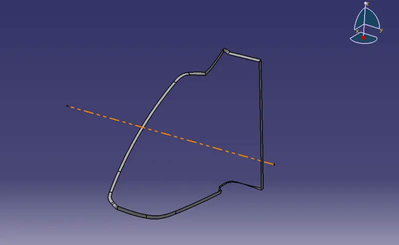
Closed surface body:
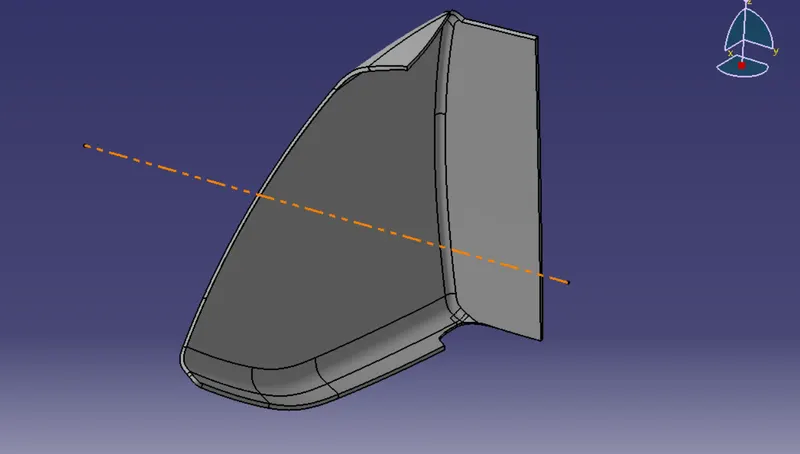
Solid part:
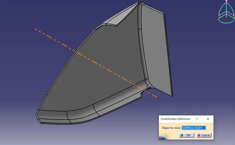
Bottle holder:
Offseting class A surface about 2.5mm for create class B surface.
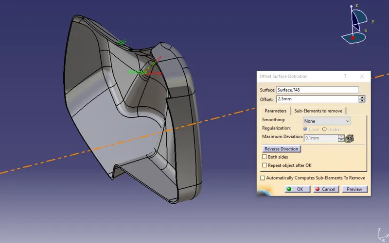
Class C surface:
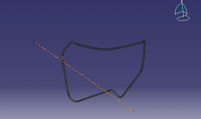
Closed surface body:
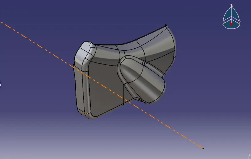
Solid part:
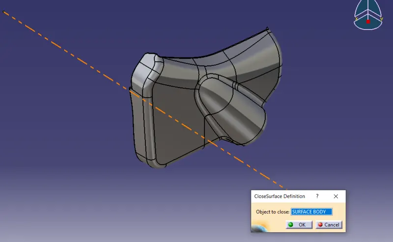
Creation of engineering features:
Engineering features are known as supporting features which are going to help the components to get assembled together and these features are helping to accommodate the plastic parts on to other features like biw.
So, in this case we’re going to make some engineering features such as
- Dog house
Dog house is the feature which supporting the other engineering features like screw boss, heat stakes for strengthening them.
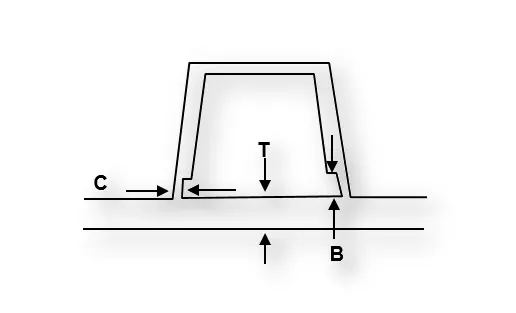
- Doghouse wall thickness at the intersection of the part wall (C) should be 40% or less than the main wall stock (T).
- Height of (B) should be between 3.0 – 6.0 mm
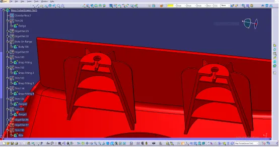
- Heat stakes
Heat stakes are using to join the plastic component to the other plastic component or metal component by heat staking or thermal staking process.
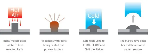
- Ribs
Also, the ribs can be a strengthening component which provide a strength to the curvy surfaces.
Design rules of ribs:
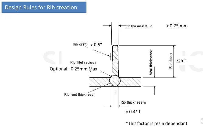
Factors that we should've take into our concern before we design a rib:
- Height
- Thickness
- Location
- Quantity and
- Produceability
Rules and regulatinons for create the ribs:
- Thickness of the rib t*0.4
- Height of the rib t*5
- Optimal radius 0.25mm
- Thickness on the top is grater than 0.75mm
- optimal draft angle for the faces is 0.5 degree
- For spacing for steel 3:1 and preffered 2:1
- Mounting flanges
These are the flanges that’s going to mate with heat stakes to make a joint between two plastic components.
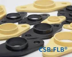
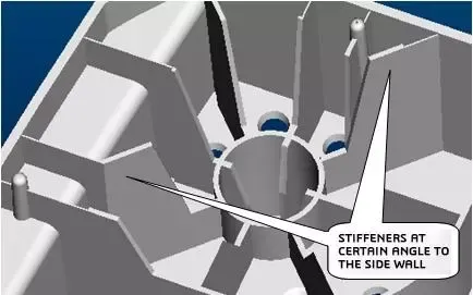
- Stiffeners
Stiffeners also supporting features that can provide a strength to heat stakes.
- Screw boss:
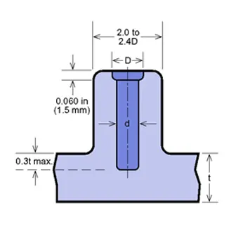
We use this feature in plastic design for get fixed with the other part by screws.
General Guidelines for Bosses:
- Draft - 0.5 degrees on walls of boss
- Thickness - Typically 40%* of the nominal wall at the base.
- Height to Diameter Ratio - 3:1
- Radii - 0.25mm maximum radii.
- 4 way and 2-way locators:
A 2-way locating pin restricts motion along 1 axis (or 2 degrees of Freedom), like a round pin in a slot. Likewise, a 4-way pin restricts 4 degrees of freedom along 2 axes. A round locating pin located concentrically in a hole is a common application of a 4-way pin, and helps to further secure the piece.
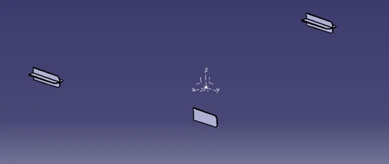
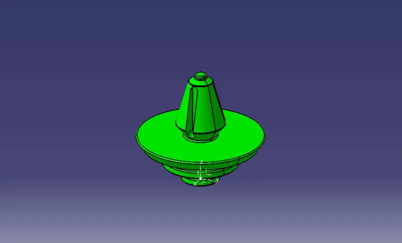
- Push pin clips:
Push pin clips can be used for joining two plastic parts seamlessly and we can reduce the weight of the components by eliminating metal screws and bolds the washers as well.
Door arm rest solid with engineering features:
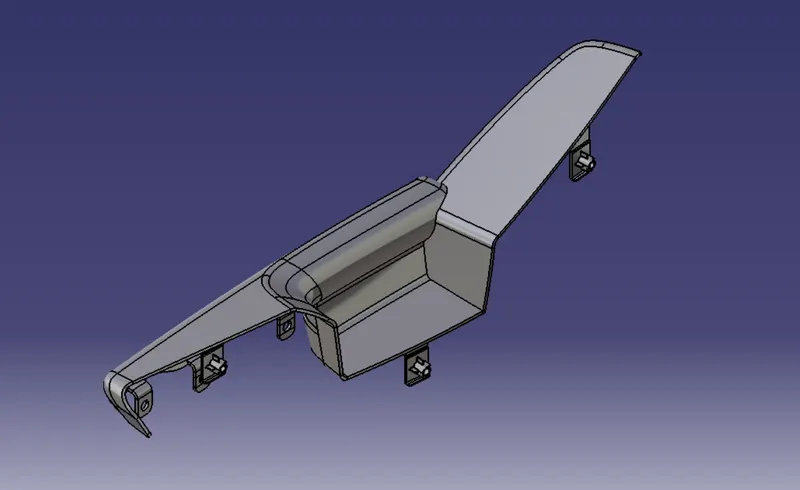
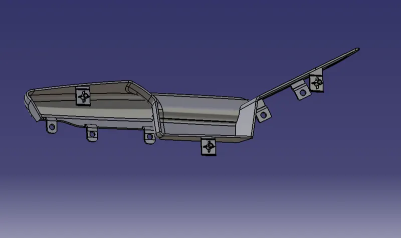
Lower substrate with engineering features:
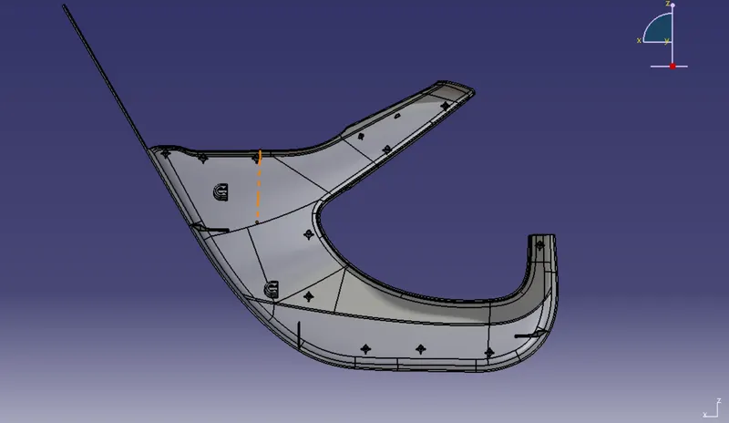
Map pocket with engineering features:
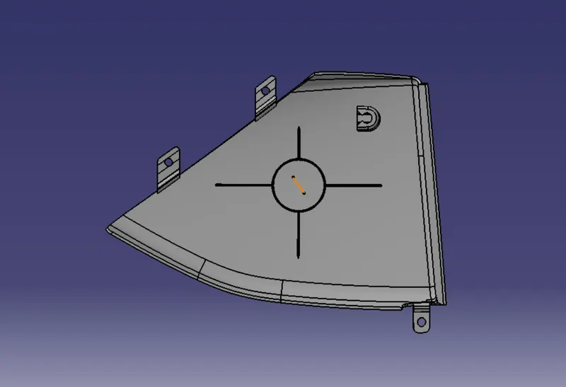
Bottle holder with engineering features:
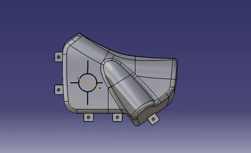
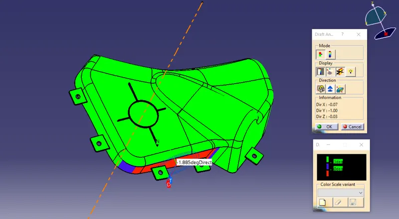
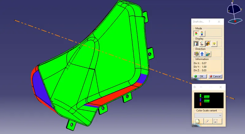
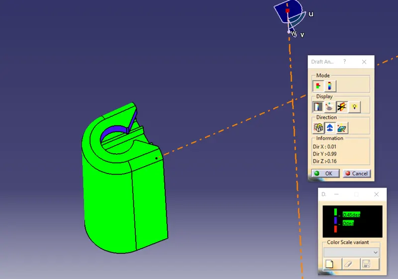
Draft analysis report of solid parts with engineering features:
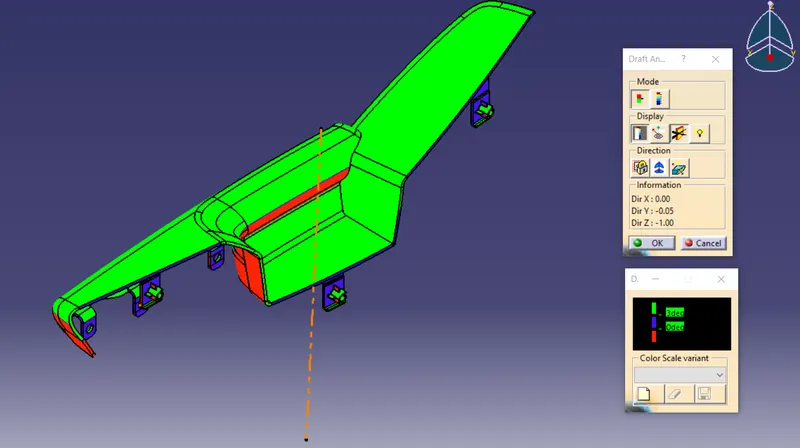
Then i created side core axis due to the shape of flanges because when the mold is open there might be a chance of braking of the flanges so that we should've the side core axis and my flanges also getting clears with the side core axis as well.
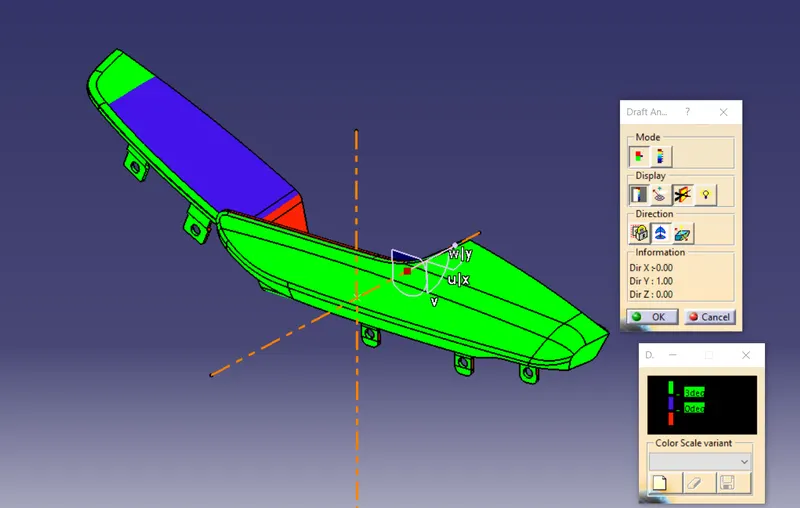
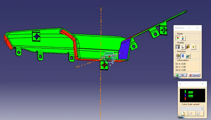
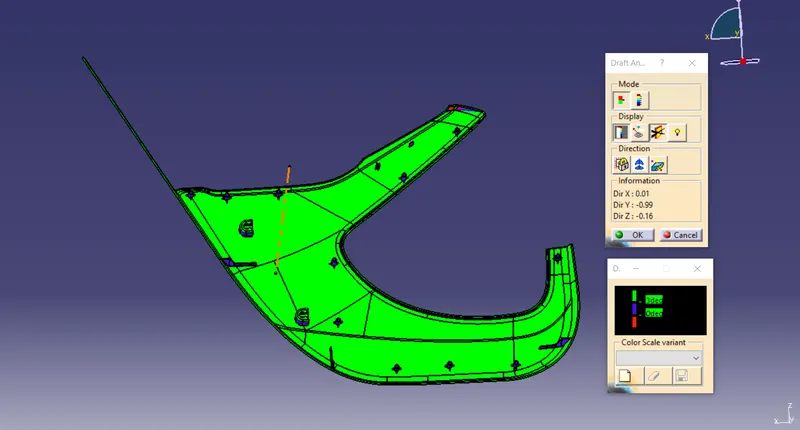
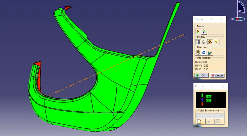
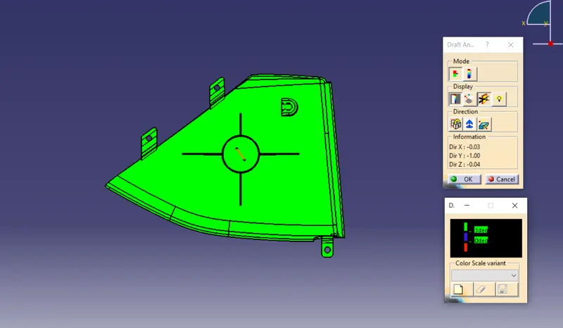
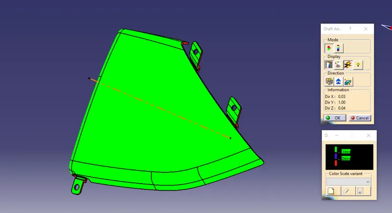
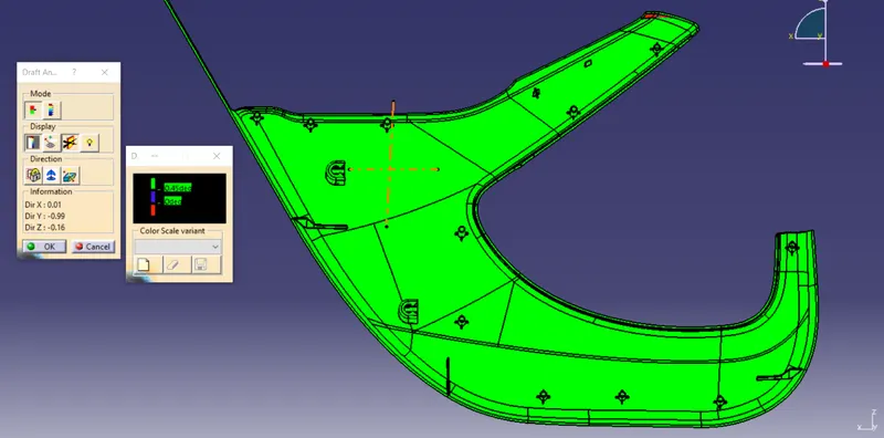
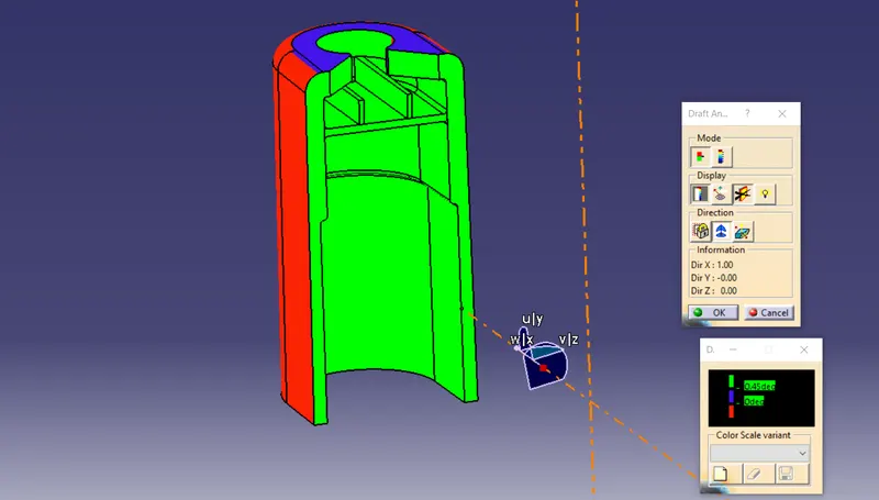
Draft analysis report on engineering features:
Material applying:
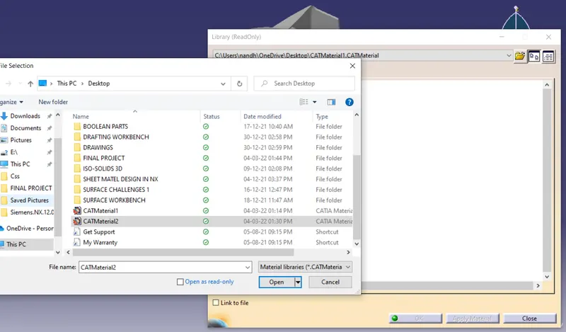
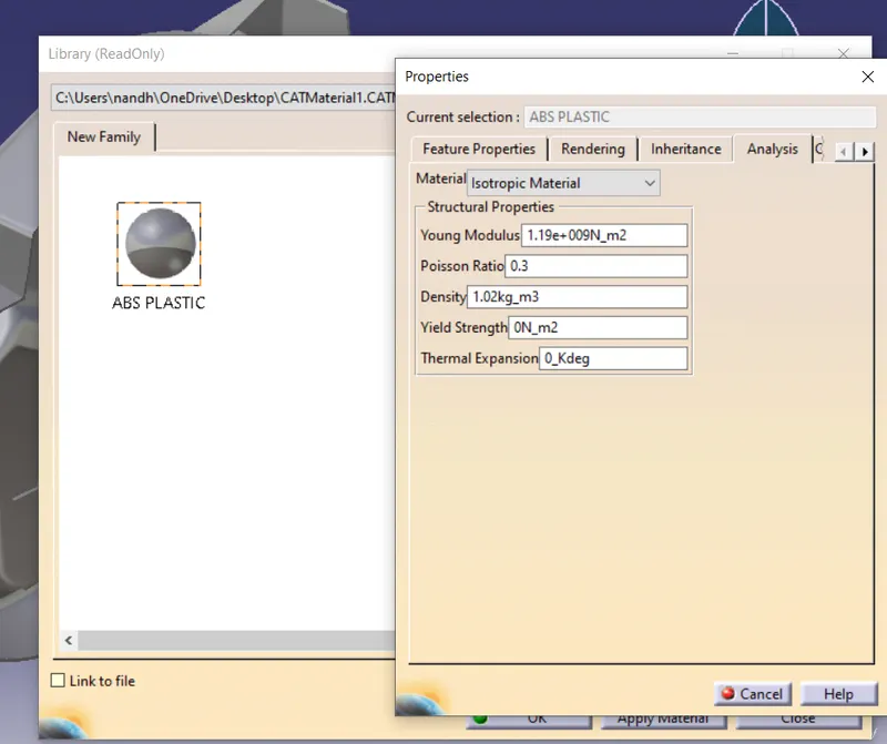
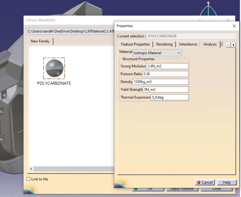
Since there are some materials are not in default material library, I've imported some materials like ABS plastic and polycarbonate.
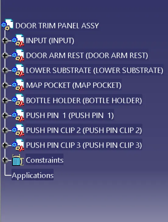
Tree structure assembly:
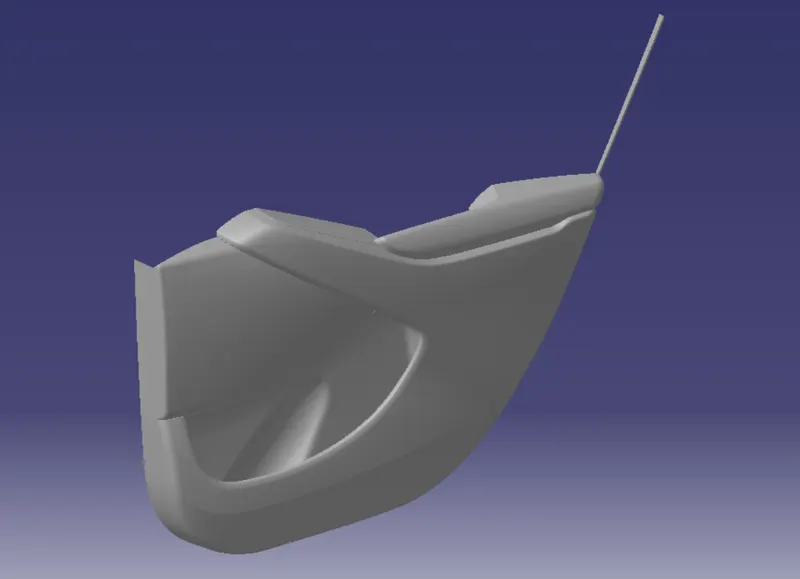
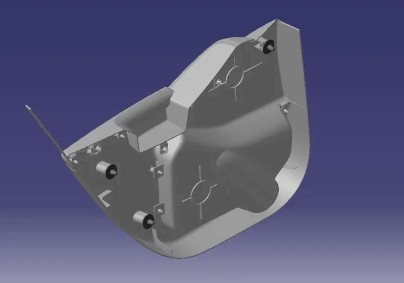
Assembled view with material applied:
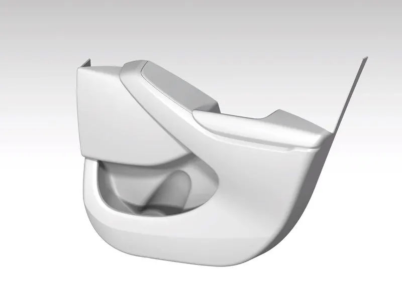
After I rendered how my side door trims will be in real life:
Class A (aesthetic) surface
Class B surface with engineering features
Conclussion:
Eventually we developed side door trims according to the standerds and norms of oem , in some areas in this project i found some issues with class A surfaces then i rectified by myself and i found some issues on class A surface as well so, i suggest to the class A team to resolve those issues, then i learnt ample of things in this project that releted with surface modeling and solidmodeling then i learnt some new tricks at solid and surface workbenches as well the days i spent on this project was get myself an pure experience of working in a project of oem.