Week 11 - Final project
AIM
To create a door interior part from the inputs of class A surface along with master section by following the design rules followed inindustries in catia v5
SOFTWARE USED
CATIA V5
OBJECTIVES
• Create a sketch by using Positioned sketch
. All the should be sketches should be Iso-Constrained
• Ensured Proper Tree Structure
• Geometrical sets should having a proper name based on the sketches present inside of it
• Create thickened part using master section for reference
• Create the mounting features as per design guidelines in the industry and with master sections
• Creating of Draft analysis
INPUT OF CLASS A SURFACE:
Since the input class A surface is containing four different parts(class A). So class b and c for all the surface has been created in separate catpart. Also performing draft analysis and tooling axis separately. finally all the surface have assembled together in one catproduct
DRAFT ANLAYSIS
Draft analysis in catia is a command that is used to detect if the part you drafted will be easily removed from the mold. it is performed based on color ranges identifying zones on the analyzed element.
Most of the industries is using minimum draft angle is 3 degree
PROCEDURE
• Check all the boundary whether it has connected or not.
. Check the model visually & choose the best tooling direction which should be easy for draft.
• After analyzing the above model.we have to create tooling axis on Y
- Creating the tooling axis
PROCEDURE TO CLASS SURFACE
1)INPUTS
Interior door trim consists of four components
1) Lower Substrate
2) Upper Substrate
3) Map Pocket
4) Door Arm Rest
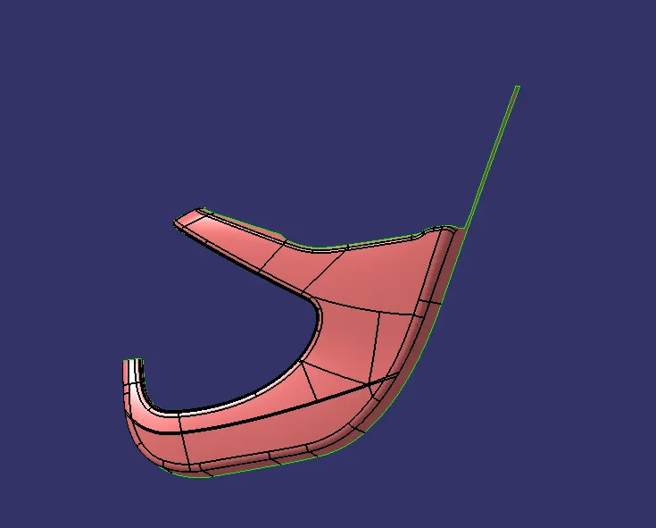
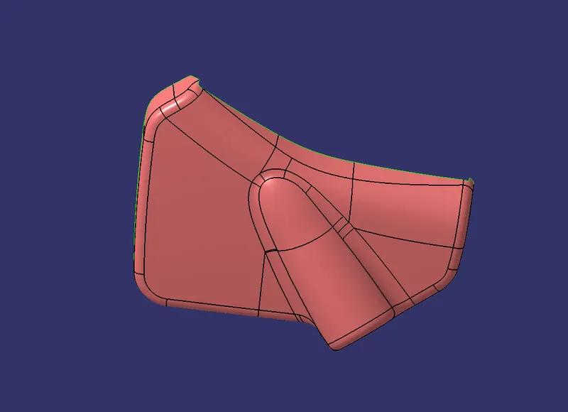
2) Class A Surface: lower substate,map pocket , bottle holder , door arm rest .
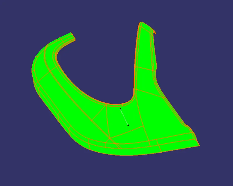
In Automotive design, a Class A Surface in any of a set of freeform surfaces of high efficiency and quality. Industrial Designers Develope their design styling through A-Surface, the physical surface the end user can feel, see, touch etc.
lower substate:
MAP POCKET:
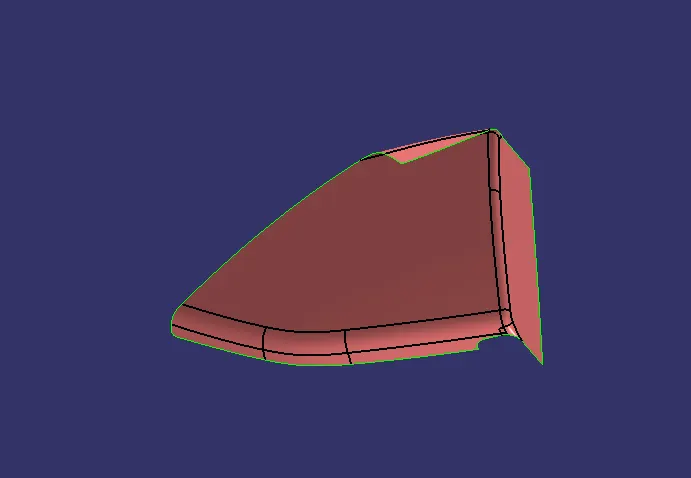
DOOR ARM REST :

BOTTLE HOLDER :
3) Class B surface:
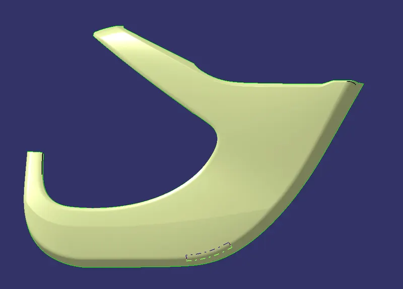
The class B - surface is which the b side features are attached like
* 4 way locater
* Dog house
* Flanges
* Screw boss
* Heat strakes
To create the B - surface we need to offset the A surface to 2.5 mm which is the thickness of the plastic part.
B surface of lower substate:
B surface of bottle holder:
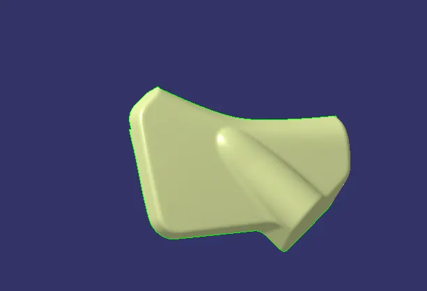
B surface of map pocket
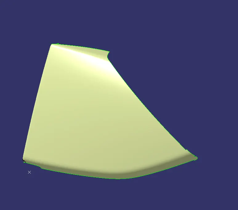
B surface of door arm rest:
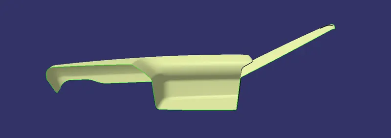
C SURFACE : lower substate , map pocket , bottle holder , door arm rest :
The surface is the to join the class A & B .
To create the C surface we need to take the boundaries of the class A.
sweep the boundaries according to the reference surface.
Join the class A with C using the JOIN command
Then trim the A&C with the B surface with TRIM command.
lower substate:
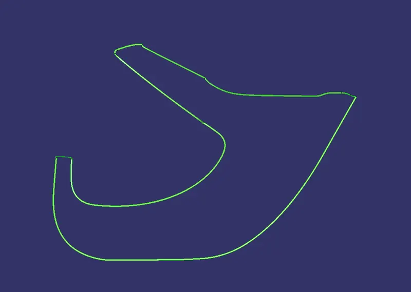
Bottle holder :
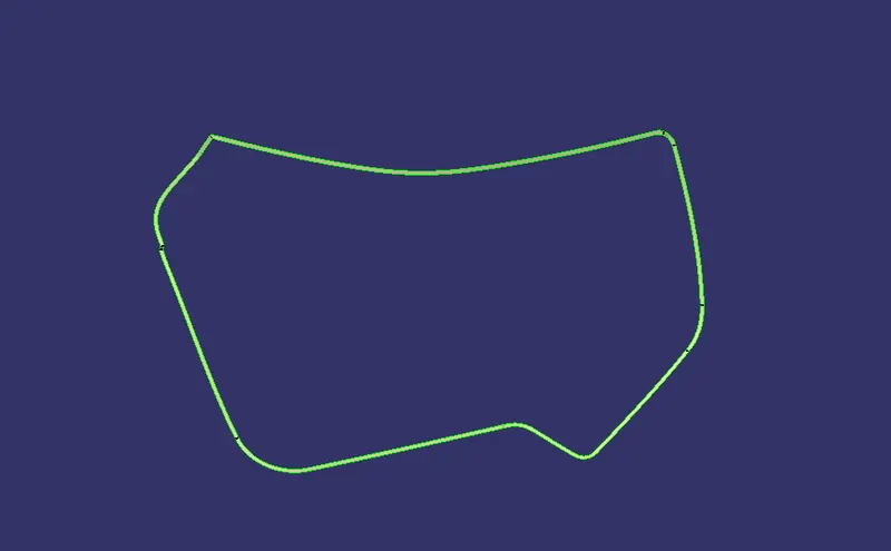
Door arm rest :
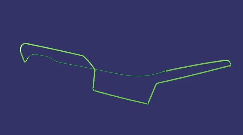
Map pocket:
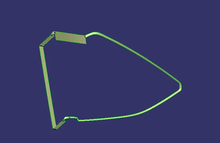
B - side features
In the B - side features we have
* Flanges
*Dog house
*Heat stakes
*4 way locaters
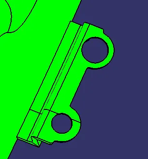
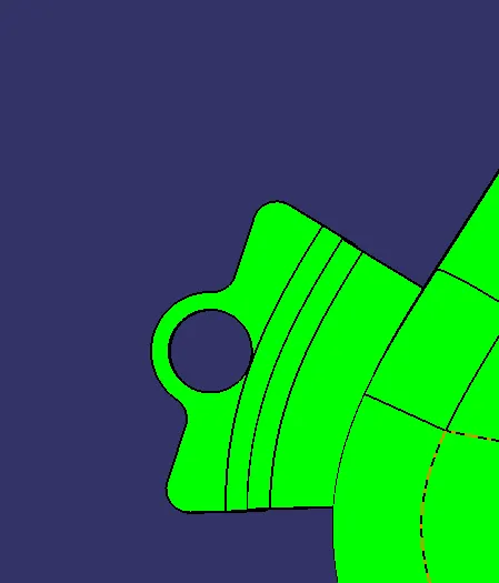
1) Flanges
Flanges are which used to increase the length of the part to attach with the other parts.
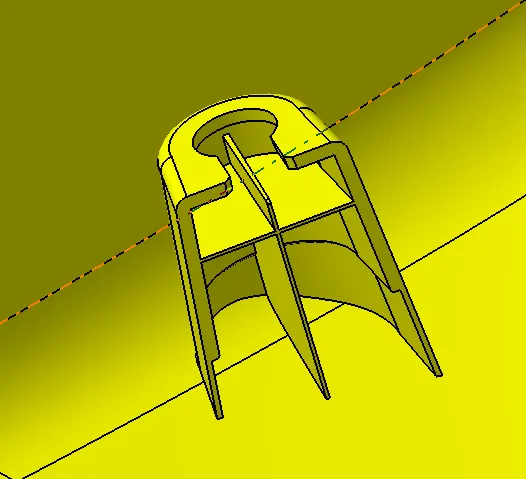
DOG HOUSE:
Dog house is used to increase the height of the push pins
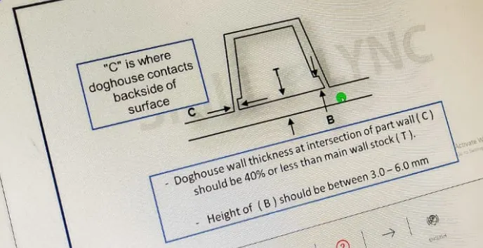
Dog House wall thickness at intersecton of the part Wall(C) should be 40% or less than the main wall stock(T).
Height of (B) should be between 3-6 mm.
DOG HOUSE RULE
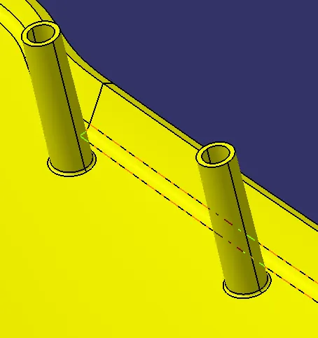
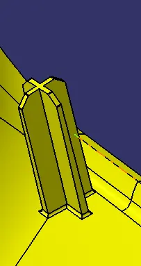
HEAT STAKES :
The heat stakes is used to strengthen the part and for mating parts.
4 Way locaters:
The 4 way locaters are used fix the parts and it acts has a mating part
DRAFT ANALYSIS:
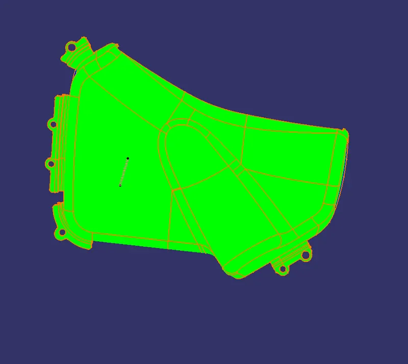
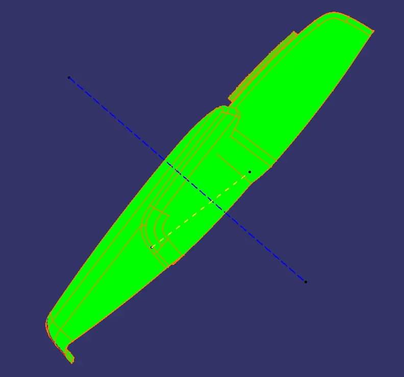
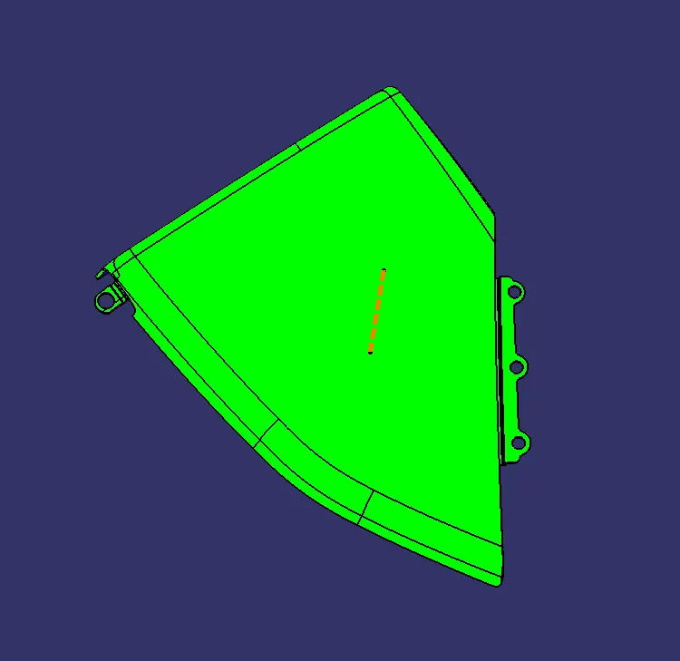
Draft analysis in catia is a command that is used to detect if the part you drafted will be easily removed from the mold. it is performed based on color ranges identifying zones on the analyzed element.
Most of the industries is using minimum draft angle is 3 degree
The draft analysis must be done on the component in order to check the draft angle provided for the component. The advisable value for the draft angle is 0.5 deg which is the nominal value for the draft in plastic component, the draft analysis done on the component on the axis where the component is moulded.The drafts are very essential for the component manufacturing, the drafts are provided on all the engineering features.
Tooling axis and side core axis are used for the draft analysis.
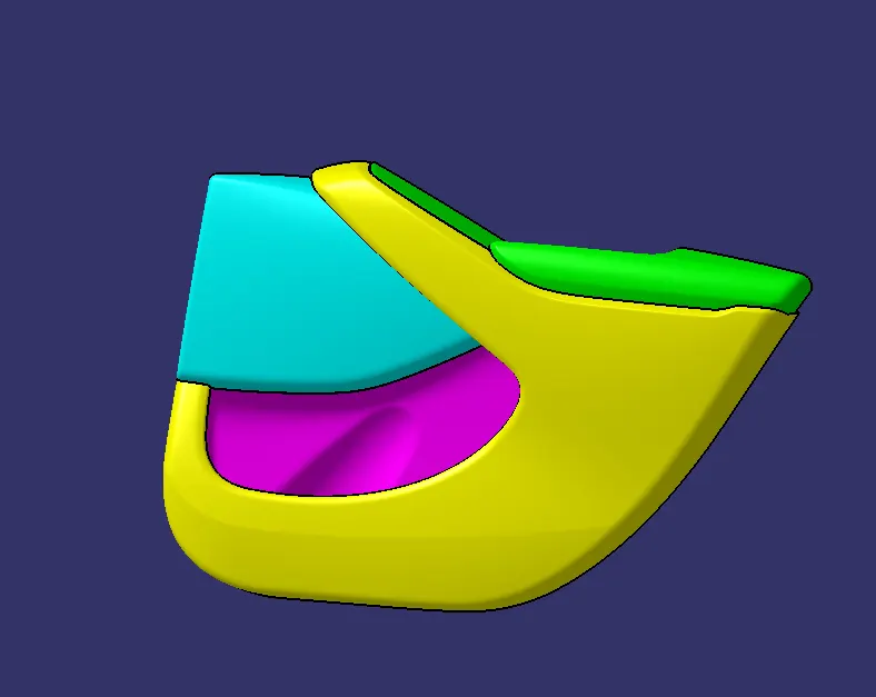
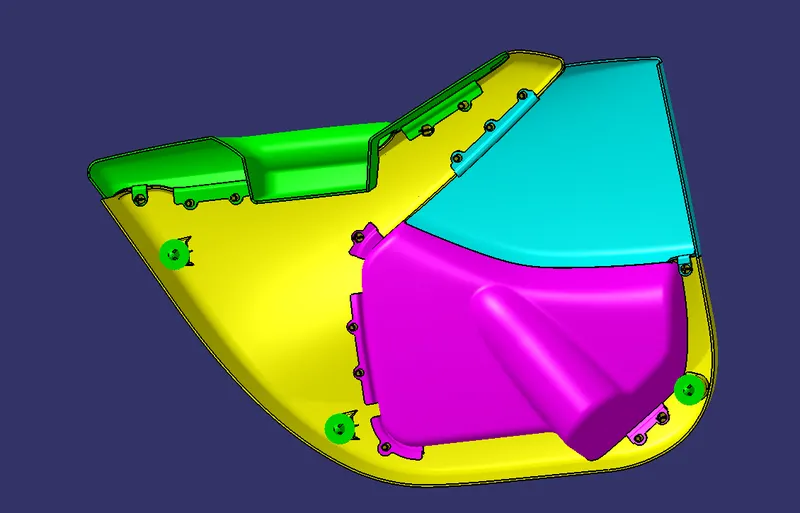
FINAL COMPONENT :
CONCLUTION:
* Class A, B and C surface was created as per the automotive standards using CATIA V5 Software.
* Draft Analysis was performed for the built model and it could be seen the the draft was under permissible limit for the manufacturing of the component.
* B side features were created for the component as per the design Rules.