Week 11 - Final project
AIM-
- Development of a Door Trim panel
Creation of CAD model considering following inputs as like in OEM and tier1 companies
- a) Class A surface
- b) Nominal thickness : Refer master sections
- c) Attachment strategy :
Find a attachment strategy for the door panel complete work.
Use Push pin with Dog house for Lower substrate – Door panel attachment
Use heat stakes for part to part attachment
THEORY:-
10 Stages of Product life cycle of automotive Industry are
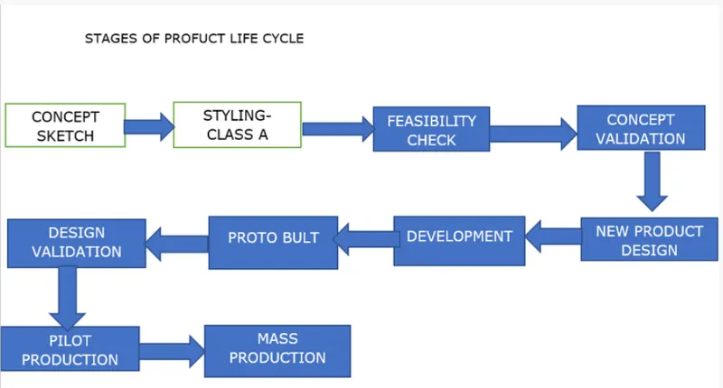
- Concept sketch
- Styling class A
- Feasibility check
- Concept validation
- New Product Design
- Product Development
- Proto Build
- Design Validation
- Pilot Production
- Mass production
- New Product Development CAD: This is the stage where the major work of product design, by taking inputs from the concept sketch to validate the product will go to design using design software such as NX, CATIA V5, Solid works, Solid Edge etc. In this stage through design all the surfaces are divided into sub parts from the class A surface and ensuring product should be workable. Making the 3D model and 2D drawings for development. Here product design is going to complete 100%.
INTRODUCTION
The different components in this project are designed following the standards followed by the industry to manufacture the component by using injection moulding technique.
The steps followed to make the components mentioned below are
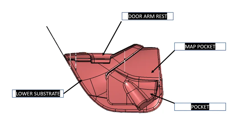
1 Arm Rest
2 Lower Substrate
- Map Pocket
STEPS USING IN CAD MODEL
1 Importing the class A surfaces of all the components from the CEM
- Determining the tooling axis of each component,
- Performing draft analysis on each component
- Desigining class B surface for each component
- Designing class C surface of each component
6 Creating a closed surface by combining the class A class B and class C surfaces and then converting it into closed body.
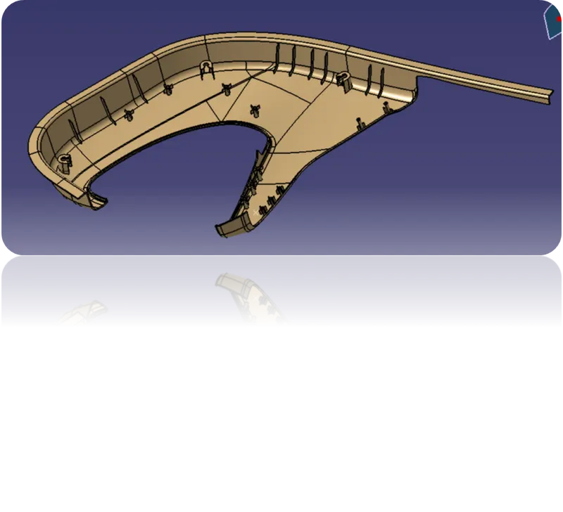
7.Designing attachment features like heat stakes. Dog house, push pins to the class 8 side of the component wherever it is required.
- Determining the tooling axis of the Dog house for safely producing the feature
- Performing the draft analysis for each Dog house
- Designing push pins on top of each dog house for further attaching the components to me Sheet Metal
PROCEDURE.
MAP POCKET
INPUT
Class A surface modification as per master section: From the given data we have to do cad model for Lower Substrate, Arm Rest and Map Pocket.
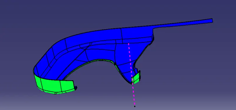
- MAP POCKET -Initially, I extracted the Class A surface required for each part from the main input. Then started working on them one by one. Here I extracted the class A surface of map pocket from input as shown below.
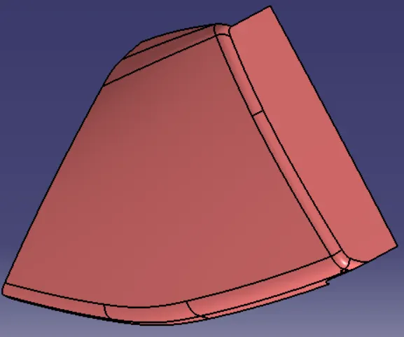
Next, main tooling axis was created by applying a zero-distance value on the surface as shown below.
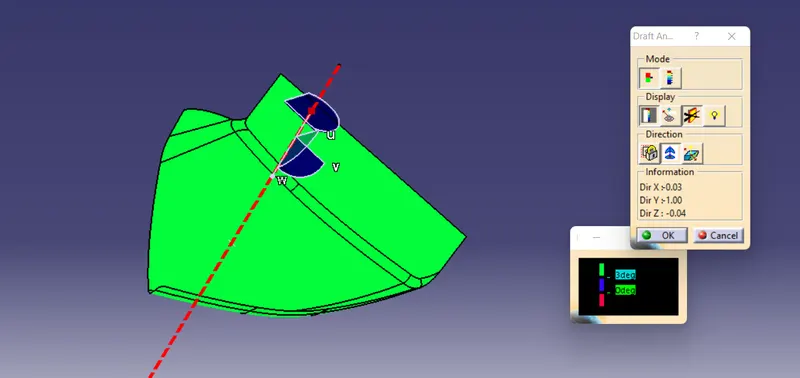
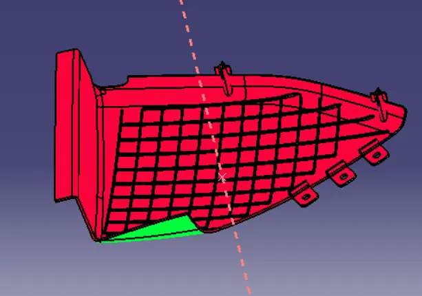
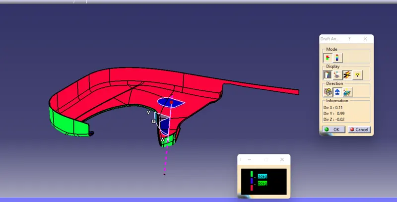
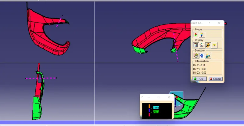
Next, the surface was inspected using draft analysis as shown below. In industry, if there is any issue with the surface after inspection, engineers must discuss the issue with the aesthetic design team whom provide the class A for troubleshooting the issue.
Class B surface development
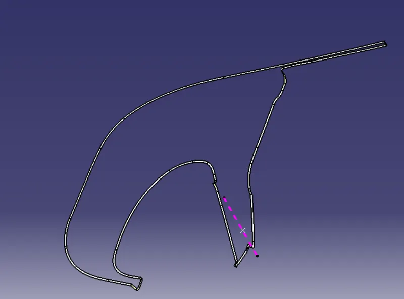
Class B surface was created from the class A surface using offset at a distance of 2.5 mm thickness.
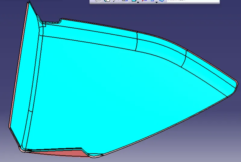
Class C surface development
Class C surface was swept along the boundary of Class A using' Sweep' option at an angle of 3 degree outwards with respect to tooling direction. In some areas 90 degree sweep was applied. Finally, all the swept surfaces were trimmed and joined together.
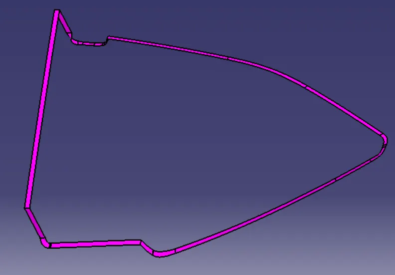
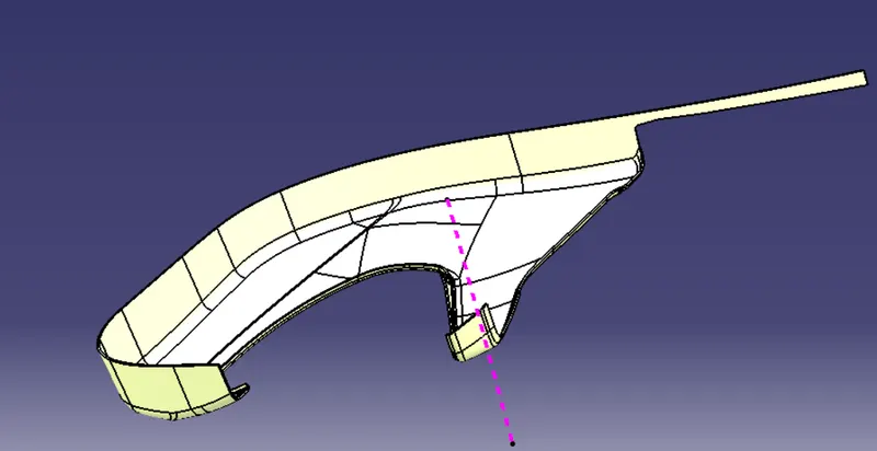
After joining Class A and C surfaces, it was trimmed together with the Class B surface in order to form the closed surface as shown below.
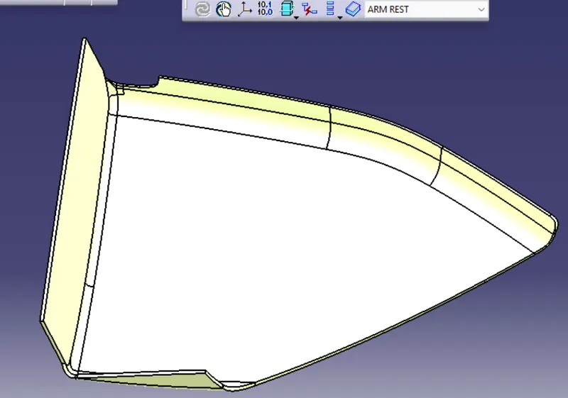
A part body was formed using the closed surface. Next step was the creation of mounting features for fixing the component on the lower substrate.
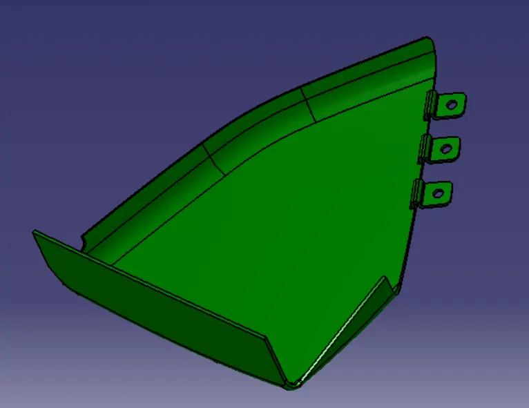
FINAL map pocket design after assembly
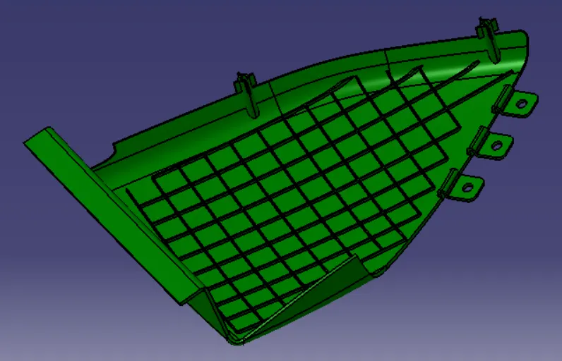
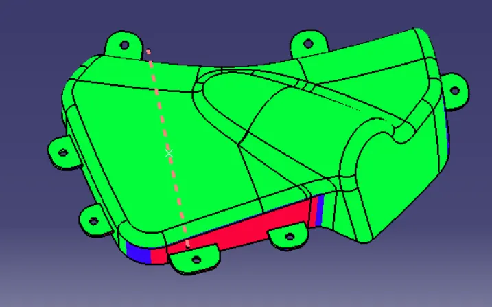
draft analysis on final product
pocket was also created by following the same steps and procedures. Initially class A surface was extracted from the input surface as shown below.
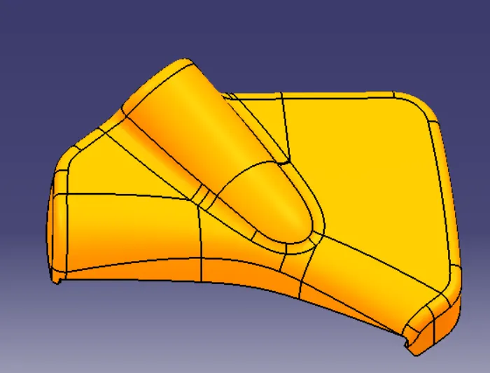
NOW I created pocket MODEL CLASS A SURFACE
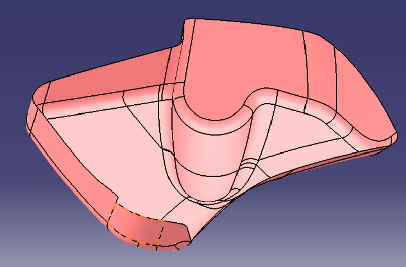
CLASS B SURFACE CREATED OFFSET OF 2.5 MM
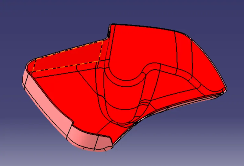
CLASS C SURFACE
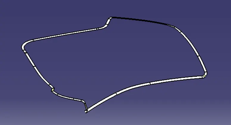
JOIN THE CLASS A SURFACE AND CLASS C WITH TRIM CLASS B
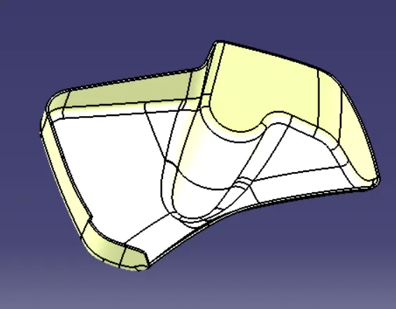
create a close surface in body
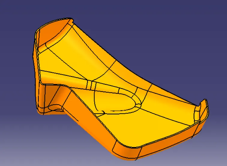
some flanges create on solid body join for other body
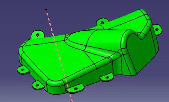
draft analysis on pocket (draft angle 3 degree)
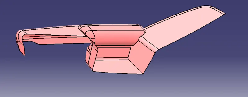
DOOR ARM REST
INPUT
Given CLASS A Surface
first of all join all surfaces and check the boundry
CREATE B SURFACES
OFFSET OF 2.5 MM ON DOWNWARD DIR
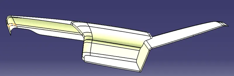
create C Surface
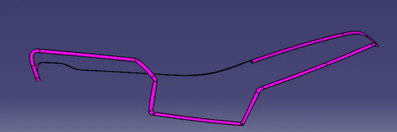
JOIN A & C SURFACE
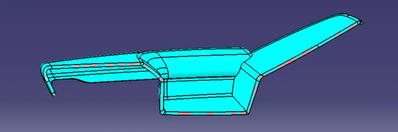
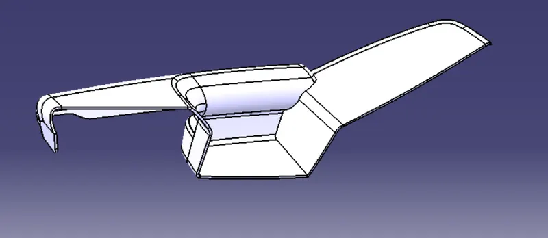
FINAL ARM REST BODY CREATE
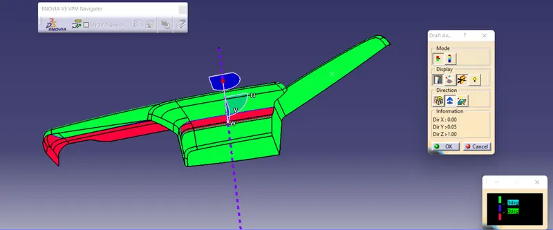
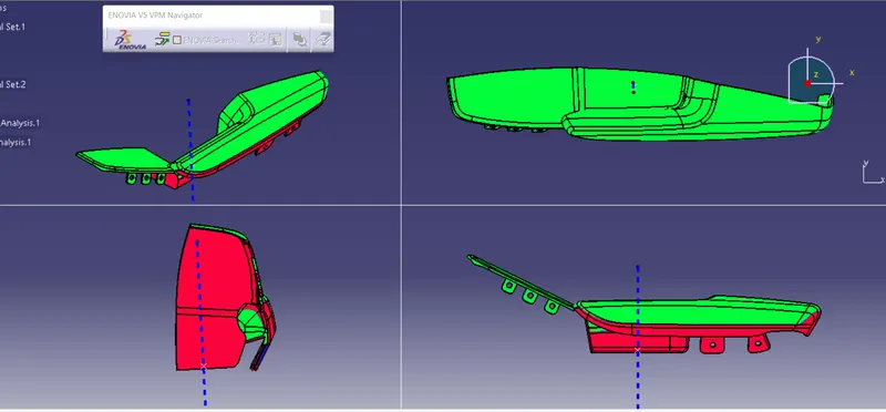
DRAFT ANALYSIS OF DOOR ARM REST
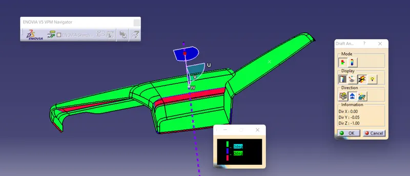
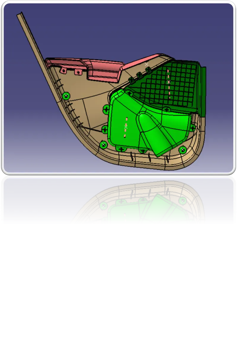
AFTER ASSY SOME CREATE A FLANGES FOR JOIN THE COMPONENT WITH HEAT STAKES & SREW BOSS
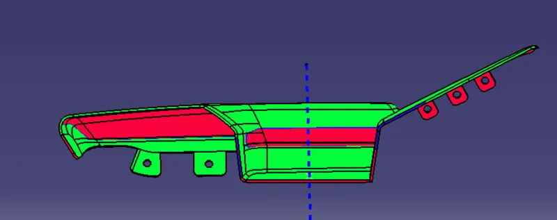
all view after draft analysis result
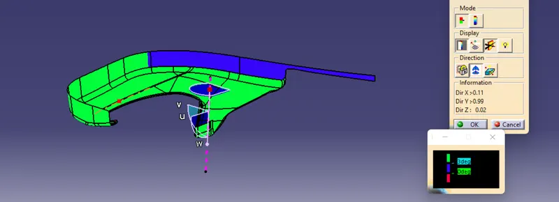
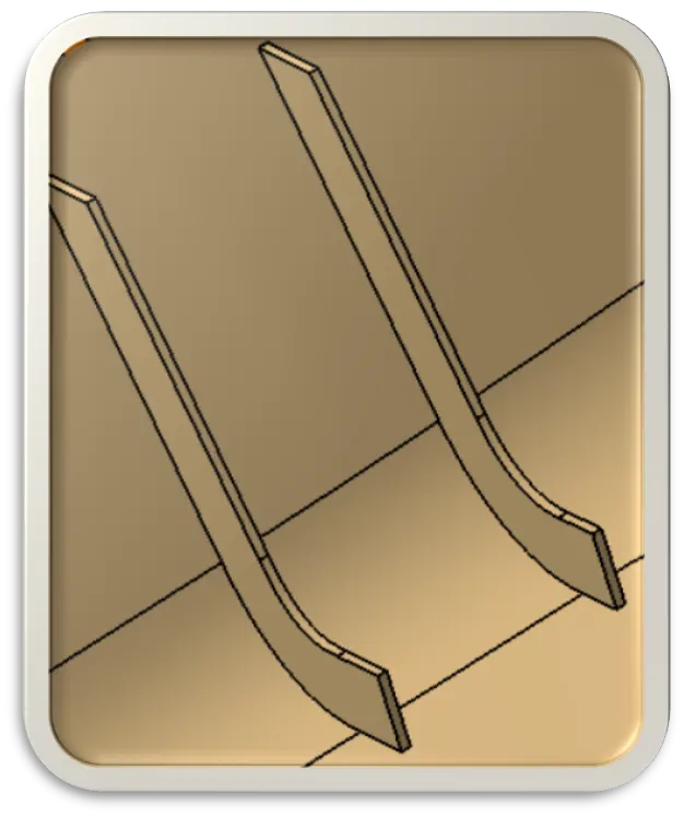
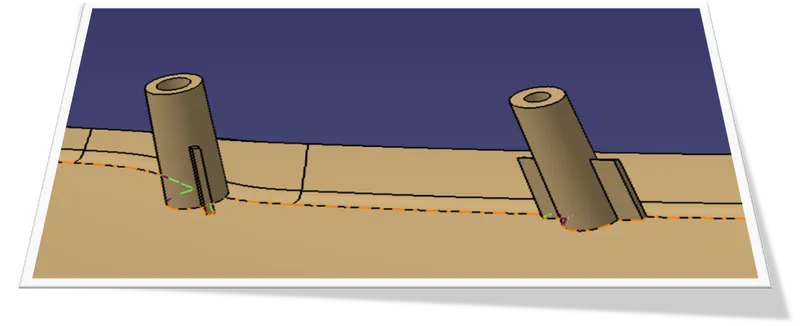
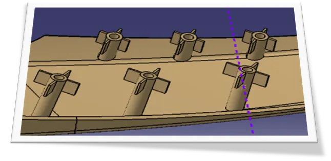
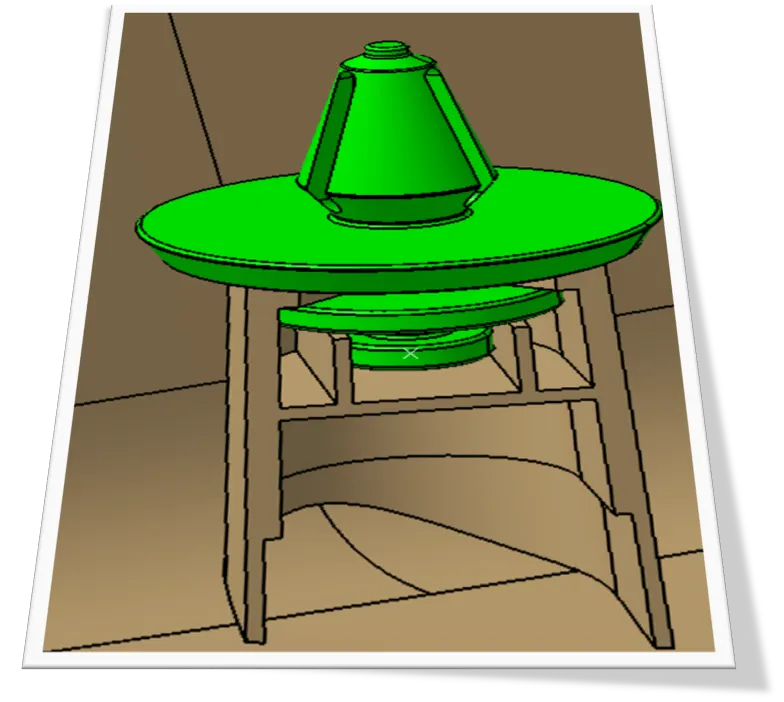
RIB HEAT STAKES SCREW BOSS DOG HOUSE
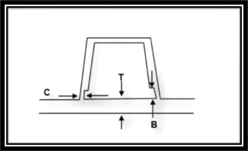
Creation of Ribs and Dog house
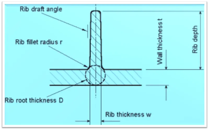
Ribs provide a economical stiffness and strength in molded parts without increasing overall wall thickness. They also facilitate,
- Locating and arresting the components of an assembly.
- Providing alignment in mating parts
- Acting as stops and guides for the mechanisms.
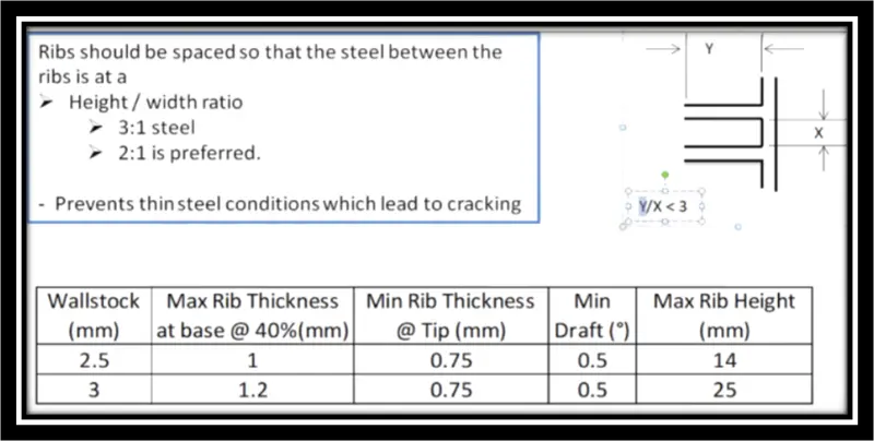
Proper rib design involves 5 main issues:
- Thickness
- Height
- Location
- Quantity
- Manufacturability
Conclusion:
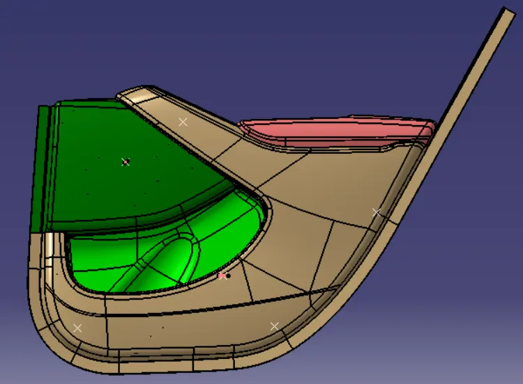
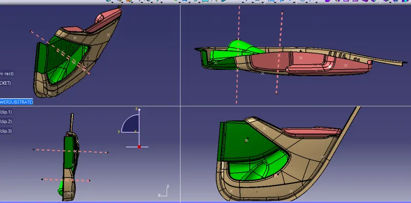
Thus the Interior trim of the Car interior door trim is designed using the given A Class Surface as the Input and B and C Class Surfaces are created with respect to the A Class Surface. By using the Given Master section attachment features i.e. Ribs and doghouse ,flanges and push clips created considering all the design rules for creation of Ribs and Dog house. Also carried out the draft analysis to check weather the Component is easily manufacturable or not with the given draft of 3 degrees for the surfaces and 0.5 degress for the attachment features. With all these datas and report we can conclude that the Draft Analysis is very important to design any Plastic Component because when we making a part that will be molded, the analysis will verify that all surfaces are favorable for being pulled from a cavity.It may also highlight or give insight to "trouble" areas.